EP0417835A1 - Lampe à incandescence électrique - Google Patents
Lampe à incandescence électrique Download PDFInfo
- Publication number
- EP0417835A1 EP0417835A1 EP90202354A EP90202354A EP0417835A1 EP 0417835 A1 EP0417835 A1 EP 0417835A1 EP 90202354 A EP90202354 A EP 90202354A EP 90202354 A EP90202354 A EP 90202354A EP 0417835 A1 EP0417835 A1 EP 0417835A1
- Authority
- EP
- European Patent Office
- Prior art keywords
- lamp
- filament
- axis
- filaments
- lamp vessel
- Prior art date
- Legal status (The legal status is an assumption and is not a legal conclusion. Google has not performed a legal analysis and makes no representation as to the accuracy of the status listed.)
- Withdrawn
Links
- 239000011248 coating agent Substances 0.000 claims abstract description 7
- 238000000576 coating method Methods 0.000 claims abstract description 7
- 239000004020 conductor Substances 0.000 claims description 6
- 238000010586 diagram Methods 0.000 description 2
- 239000000463 material Substances 0.000 description 2
- 241000826860 Trapezium Species 0.000 description 1
- XAGFODPZIPBFFR-UHFFFAOYSA-N aluminium Chemical compound [Al] XAGFODPZIPBFFR-UHFFFAOYSA-N 0.000 description 1
- 229910052782 aluminium Inorganic materials 0.000 description 1
- 239000004411 aluminium Substances 0.000 description 1
- 230000015572 biosynthetic process Effects 0.000 description 1
- 230000008021 deposition Effects 0.000 description 1
- 230000008020 evaporation Effects 0.000 description 1
- 238000001704 evaporation Methods 0.000 description 1
- 230000004907 flux Effects 0.000 description 1
- 239000012212 insulator Substances 0.000 description 1
Images

Classifications
-
- H—ELECTRICITY
- H01—ELECTRIC ELEMENTS
- H01K—ELECTRIC INCANDESCENT LAMPS
- H01K1/00—Details
- H01K1/18—Mountings or supports for the incandescent body
-
- H—ELECTRICITY
- H01—ELECTRIC ELEMENTS
- H01K—ELECTRIC INCANDESCENT LAMPS
- H01K9/00—Lamps having two or more incandescent bodies separately heated
Definitions
- the invention relates to an electric incandescent lamp to be operated at mains voltage comprising: . a translucent lamp vessel with an axis, which is provided with a reflective coating, . a first and a second wound filament having end portions, which are arranged in the lamp vessel near the axis thereof, . which filaments are connected at their end portions to current supply conductors emanating from the lamp vessel and are arranged electrically in parallel.
- Such a lamp is known from NL 121 505.
- the filaments are arranged linearly at an angle of 45° to the axis and at right angles or parallel to each other.
- This shape and this arrangement result in that portions of the filaments are located at a great distance from the axis of the lamp vessel. This has the consequence that the light beam formed by the reflective coating of the lamp vessel has a large width and hence a low luminous intensity at the centre. Another consequence is that the light beam is inhomogeneous and not rotation-symmetrical.
- the filaments may have different powers, for example one twice that of the other.
- EP 0280475-A discloses a lamp having two transversely arranged filaments constituting a closed figure. One of these filaments is designed for a longer life than the other. Thus, it is achieved that the lamp continues to emit light for a long time when a first filament has already burnt through.
- Such a lamp is not efficient because the longer life of the filament having the longest life is inevitably coupled with a low light output per unit energy consumed.
- the net light emission of the filament having the longest life is lower than the gross light emission thereof because due to evaporation of the material of the filament having the shortest life after it has burnt through, an absorbing deposit of evaporated filament material has formed on the lamp vessel.
- the filament In incandescent lamps having a reflective coating, the filament is mostly arranged transversely so as to be bent around the axis of the filament.
- a filament is known from US 4,777,300. Due to the comparatively great length of an incandescent filament to be operated at mains voltage, this filament extends, also when it is arranged so as to be bent around the axis, at a comparatively great distance from the axis. This results in a comparatively large width of the light beam formed.
- Other consequences of the position and the shape of the filament are the formation of a non-symmetrical beam and a comparatively low luminous intensity at the centre thereof.
- the invention has inter alia for its object to provide a lamp of the kind described in the opening paragraph, which has a more symmetrical light beam having a high luminous intensity at the centre of the beam.
- this object is achieved in that - the first and the second filament are similar and together constitute a polygon, - are supported between their end portions by supporting members and - are arranged mainly at the mirror image places one of the other and mainly transversely to the axis.
- the filaments each have a smaller length than one filament having this power, for example with a lamp for 220 V 19 mm instead of 24 mm.
- the filaments are located closer to the axis of the lamp vessel than with a lamp having only one filament.
- a conventional filament having the form of a trapezium open at its base extends at a greater distance from the axis than the filaments of a lamp according to the invention when they constitute, shaped and arranged in a corresponding manner, together a regular hexagon. Both their maximum distance and their average distance are only 80% of that of the conventional filament. Thus, a narrow light bear and a high luminous intensity at the centre thereof are obtained. The luminous intensity of the beam is more than 20% higher.
- the lamp has filaments which are similar, that is to say that they have the same specification, such as length and wire thickness. Nevertheless, filaments having the same specification, even of the same lot, may have unequal properties, especially unequal lives. This may be due, for example, to an error in the filament wire, as a result of which this wire is locally thinner. This results in a shorter life. In a lamp having a first and a second filament, in an extreme case one filament could burn through after 700 hours, while the other filament can continue to emit light for 300 further hours.
- a measure is taken by which the second filament burns through a very short time after the first filament, also if the first filament burns through very early.
- corresponding supporting members of the first and the second filament are electrically connected to each other.
- the electric incandescent lamp to be operated at mains voltage has a translucent lamp vessel 1 with an axis 2.
- the lamp vessel is provided with a reflective coating 3, for example a layer of aluminium applied by vapour deposition.
- a first and a second wound filament 4 and 5, respectively, (see also Fig. 2) having end portions 6, 7 and 8, 9, respectively, are arranged in the lamp vessel 1 near the axis 2 thereof. They are connected at their end portions 6, 7 and 8, 9, respectively, to current supply conductors 10, 11, which emanate from the lamp vessel.
- the filaments are connected electrically in parallel.
- the lamp shown has an Edison lamp cap 12 provided with contacts 13, 14, to which a respective current supply conductor 10, 11 is connected.
- the mirror-coated part of the lamp vessel 1 is parabolic; this part could have been shaped differently, for example in the form of an ellipse, or by rotating a curve, for example a branch of a parabola or an arc of a circle, about the axis 2.
- the filaments 4, 5 are similar and together constitute a polygon, in the drawing a hexagon. They are supported between their end portions 6, 7 and 8, 9, respectively, by supporting members 15, 16 and 17, 18, respectively, which are anchored in an insulator body 20.
- the filaments 4, 5 are arranged in the lamp vessel 1 mainly at the mirror image places one of the other and mainly in a plane 19 transverse to the axis 2.
- the focus of the paraboloid lies in the plane 19 on the axis 2.
- Corresponding supporting members 15, 17 and 16, 18, respectively, of the first and the second filament are interconnected pairwise.
- the filament 4 of Fig. 2 is represented in the form of three series-connected equal resistors 40-42.
- the filament 5 is represented in the form of series-connected resistors 50-52 having the same value R also equal to that of 40-42.
- the voltage across the resistor 40 is higher.
- the equivalent resistance of the resistors 41 and 51 and of 42 and 52 is each time 1/2 R.
- the voltage across the resistor 40 has therefore increased from 2/6 u V to 3/6 u V, that is to say by 50% of the original voltage.
- a filament 4 has a life which is 0.35% of the nominal life.
- the filament 5 having a usual nominal life of 1000 hours burns through prematurely after 700 hours, at the nominal voltage 300 operating hours are still left for the filament 5. Due to the measure taken, these remaining operating hours are reduced to 0.35% thereof, i.e. to about 1 hour.
- a lamp having a high light quality can thus not continue to burn as an ordinary lamp of low power and low light quality for a long time.
- the overvoltage in a part of the filament burning for the longest time is 33.33% and the remaining life is reduced to 1.8%.
- the overvoltage in a part of the filament having the longest life is 60% and the remaining life is reduced still further than in the case shown in the drawing.
- a larger number of supportini members reduces the efficiency of the lamp due to heat losses.
- a smaller number of supporting members favourably influences the efficiency of the lamp, but unfavourably influences the luminous flux in the light beam due to the fact that the filaments are arranged farther from the axis of the lamp vessel. In general, one or two supporting members per filament are therefore chosen.
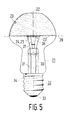
- Fig. 5 parts corresponding to parts of Fig. 1 have a reference numeral which is 20 higher.
- the filaments 24, 25 lie in the plane 39 transverse to the axis 22 coinciding with the largest diameter of the lamp vessel 21.
- the lamp shown is a bowl mirror lamp intended to be used in ar external parabolic reflector.
- the lamp vessel 21 for this purpose has a reflective coating 23 on the surface remote from the lamp cap 32, which is curved along an arc of a circle, whose centre of curvature 23′ is located on the other side of the axis 22 and of the plane 39 in which the filaments are positioned.
- the filaments 24, 25 and the supporting members 37, 38 have the geometry of Fig. 2.
Landscapes
- Non-Portable Lighting Devices Or Systems Thereof (AREA)
Applications Claiming Priority (2)
| Application Number | Priority Date | Filing Date | Title |
|---|---|---|---|
| NL8902259 | 1989-09-11 | ||
| NL8902259 | 1989-09-11 |
Publications (1)
| Publication Number | Publication Date |
|---|---|
| EP0417835A1 true EP0417835A1 (fr) | 1991-03-20 |
Family
ID=19855286
Family Applications (1)
| Application Number | Title | Priority Date | Filing Date |
|---|---|---|---|
| EP90202354A Withdrawn EP0417835A1 (fr) | 1989-09-11 | 1990-09-05 | Lampe à incandescence électrique |
Country Status (3)
| Country | Link |
|---|---|
| EP (1) | EP0417835A1 (fr) |
| JP (1) | JPH03101050A (fr) |
| HU (1) | HU203615B (fr) |
Families Citing this family (1)
| Publication number | Priority date | Publication date | Assignee | Title |
|---|---|---|---|---|
| SE469712B (sv) * | 1990-10-15 | 1993-08-30 | Sintercast Ltd | Foerfarande foer framstaellning av gjutjaern med kompakt grafit |
Citations (2)
| Publication number | Priority date | Publication date | Assignee | Title |
|---|---|---|---|---|
| US2278837A (en) * | 1940-10-31 | 1942-04-07 | Castro Adolphe De | Incandescent lamp |
| FR1258680A (fr) * | 1959-06-24 | 1961-04-14 | Patent Treuhand Ges Fuer Elektrische Gluehlampen Mbh | Lampe électrique à incandescence |
-
1990
- 1990-09-05 EP EP90202354A patent/EP0417835A1/fr not_active Withdrawn
- 1990-09-07 HU HU582890A patent/HU203615B/hu unknown
- 1990-09-10 JP JP23725890A patent/JPH03101050A/ja active Pending
Patent Citations (2)
| Publication number | Priority date | Publication date | Assignee | Title |
|---|---|---|---|---|
| US2278837A (en) * | 1940-10-31 | 1942-04-07 | Castro Adolphe De | Incandescent lamp |
| FR1258680A (fr) * | 1959-06-24 | 1961-04-14 | Patent Treuhand Ges Fuer Elektrische Gluehlampen Mbh | Lampe électrique à incandescence |
Also Published As
| Publication number | Publication date |
|---|---|
| JPH03101050A (ja) | 1991-04-25 |
| HU203615B (en) | 1991-08-28 |
| HUT54830A (en) | 1991-03-28 |
Similar Documents
| Publication | Publication Date | Title |
|---|---|---|
| US5268613A (en) | Incandescent illumination system | |
| HU218060B (hu) | Villamos izzólámpa és világítótest az izzólámpához | |
| NL8402397A (nl) | Gloeidraadlamp. | |
| US6777859B1 (en) | Light source | |
| JP4461019B2 (ja) | 電気ランプ/反射器ユニット | |
| JP2006508505A5 (fr) | ||
| NL8402395A (nl) | Gloeidraad lampbron, die een integrale cilindrische transparante warmtespiegel toepast. | |
| EP0735571A2 (fr) | Lampe à incandescence | |
| US5079474A (en) | Electric incandescent lamp | |
| JP4567196B2 (ja) | 赤外線反射膜を有した電気的な白熱ランプ | |
| EP0417835A1 (fr) | Lampe à incandescence électrique | |
| US6690103B1 (en) | Incandescent light bulb with variable pitch coiled filament | |
| US6690102B2 (en) | Electric lamp | |
| US2524455A (en) | Mount assembly for sun lamps | |
| JPH0364850A (ja) | 反射電球 | |
| CN1287417C (zh) | 卤素白炽灯 | |
| HU193869B (en) | Device for controllable feeding amount of stocks by drawing | |
| US20020067109A1 (en) | Garage lamp | |
| US1048017A (en) | Incandescent lamp. | |
| US1543141A (en) | Lamp | |
| JP4380677B2 (ja) | 管球、反射鏡付き管球および照明装置 | |
| RU2251758C2 (ru) | Источник света | |
| JPH0721996A (ja) | 電球および反射鏡付電球 | |
| JPH0917394A (ja) | 電球および反射鏡付電球ならびに照明装置 | |
| JP2002015708A (ja) | 白熱電球および照明装置 |
Legal Events
| Date | Code | Title | Description |
|---|---|---|---|
| PUAI | Public reference made under article 153(3) epc to a published international application that has entered the european phase |
Free format text: ORIGINAL CODE: 0009012 |
|
| AK | Designated contracting states |
Kind code of ref document: A1 Designated state(s): BE DE ES FR GB IT NL |
|
| 17P | Request for examination filed |
Effective date: 19910917 |
|
| 17Q | First examination report despatched |
Effective date: 19930908 |
|
| STAA | Information on the status of an ep patent application or granted ep patent |
Free format text: STATUS: THE APPLICATION IS DEEMED TO BE WITHDRAWN |
|
| 18D | Application deemed to be withdrawn |
Effective date: 19950403 |