EP0417892A1 - Verriegelungs- und Ausstossmechanismus für Verbindersystem - Google Patents
Verriegelungs- und Ausstossmechanismus für Verbindersystem Download PDFInfo
- Publication number
- EP0417892A1 EP0417892A1 EP90307997A EP90307997A EP0417892A1 EP 0417892 A1 EP0417892 A1 EP 0417892A1 EP 90307997 A EP90307997 A EP 90307997A EP 90307997 A EP90307997 A EP 90307997A EP 0417892 A1 EP0417892 A1 EP 0417892A1
- Authority
- EP
- European Patent Office
- Prior art keywords
- connector
- shroud
- locking
- connectors
- inner parts
- Prior art date
- Legal status (The legal status is an assumption and is not a legal conclusion. Google has not performed a legal analysis and makes no representation as to the accuracy of the status listed.)
- Withdrawn
Links
Images


Classifications
-
- H—ELECTRICITY
- H01—ELECTRIC ELEMENTS
- H01R—ELECTRICALLY-CONDUCTIVE CONNECTIONS; STRUCTURAL ASSOCIATIONS OF A PLURALITY OF MUTUALLY-INSULATED ELECTRICAL CONNECTING ELEMENTS; COUPLING DEVICES; CURRENT COLLECTORS
- H01R13/00—Details of coupling devices of the kinds covered by groups H01R12/70 or H01R24/00 - H01R33/00
-
- H—ELECTRICITY
- H01—ELECTRIC ELEMENTS
- H01R—ELECTRICALLY-CONDUCTIVE CONNECTIONS; STRUCTURAL ASSOCIATIONS OF A PLURALITY OF MUTUALLY-INSULATED ELECTRICAL CONNECTING ELEMENTS; COUPLING DEVICES; CURRENT COLLECTORS
- H01R13/00—Details of coupling devices of the kinds covered by groups H01R12/70 or H01R24/00 - H01R33/00
- H01R13/62—Means for facilitating engagement or disengagement of coupling parts or for holding them in engagement
- H01R13/629—Additional means for facilitating engagement or disengagement of coupling parts, e.g. aligning or guiding means, levers, gas pressure electrical locking indicators, manufacturing tolerances
- H01R13/62983—Linear camming means or pivoting lever for connectors for flexible or rigid printed circuit boards, flat or ribbon cables
- H01R13/62994—Lever acting on a connector mounted onto the flexible or rigid printed circuit boards, flat or ribbon cables
Definitions
- connector systems include a first electrical connector whose mating end or region enters a shroud of a second electrical connector as the connectors are mated. It is often desirable to provide a mechanism that can be easily operated to lock the connectors together, and to eject the first connector from the second in a manner to easily overcome the resistance to initial unmating.
- Existing mechanisms of this type are located outside the connectors, as a totally "add-on" feature that involves minimal alteration of the existing connector. As a result, the locking mechanism adds substantially to the width and length of the system, which prevents its use in applications where there is limited space, especially in the width of the connector system.
- existing locking/ejecting mechanisms systems may engage locations on a pair of connectors that are spaced far from the matable inner regions of the connectors.
- the mechanism operates at locations where there is an accumulation of tolerances and the mechanism must be loose or the tolerances of the connectors must be held close.
- a connector system which includes a pair of matable connectors and a mechanism for locking them together in a mated position and for ejecting one from the other, which is of simple and compact construction.
- a pair of locking/ejecting devices are pivotally mounted at opposite ends of a first connector whose matable inner region enters a shroud at the inner region of a second connector during mating.
- Each locking device has an inner part with a latch that is received in an undercut slot of the second connector.
- the shroud of the second connector has openings communicating with the undercut slots, with the inner parts of the locking devices passing into the openings as the connectors are mated.
- the inner part of each locking device has a thickness about the same as that of the shroud, so the inner part covers the shroud opening but does not substantially increase the overall width of the connector system.
- Each locking/ejecting device includes an eject part, that can be constructed to press against the base of the second connector when the locking device is pivoted to an eject position.
- Each locking device at each end of the first connector can include two inner parts lying on opposite sides of the fist connector, and a bridging part that connects them.
- Figure 1 illustrates a connector system 10 which includes first and second connectors 12,14 that have matable inner regions 16,18. When the inner regions are brought together, contacts 20,22 on the two connectors are mated.
- the contacts of the first connector have insulation-displacing ends 24 that engage conductors 26 of a ribbon cable 28 at the outer end 30 of the first connector.
- the contacts of the second connector have ends 32 that extend through plated-through holes (not shown) in a circuit board 34 to connect to conductive traces (not shown) on the underside of the board.
- the outer end 36 of the second connector is connected to a ground plane 38 on the circuit board.
- a locking/ejecting mechanism 40 is provided, which helps to lock the mated connectors together, and which is especially useful in ejecting the first connector from the second when they are to be unmated.
- the mechanism includes a pair of locking/ejecting devices or members 42,44 mounted at the opposite ends 46,48 of the first connector 12.
- a pair of trunnions or shafts 50,52 ( Figure 2) are received in holes 54,56 in each locking member to pivotally mount the locking member about a pivot axis 60 or 62.
- the inner region 18 ( Figure 3) of the second connector 14 includes a shroud 61 that largely surrounds the mating regions of the two connectors to protect the contacts. it is often only necessary to prevent the penetration of large mechanical objects into the mating region, and not to prevent the entrance of fluid or very small particles.
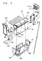
- Applicant forms openings 62,64,66,68 ( Figure 2) in the shroud, extending from the outer edge 69 of the shroud to the base 112 of the second connector. The openings receive part of the locking members 42,44, to minimise the width W of the system when the locking/ejecting mechanism is included therein.
- Each locking device or member such as 42 includes a pair of inner parts 74,76 lying in the openings 62,64 at the opposite sides 80,82 of the first connector.
- Each locking member also includes a bridging part 84 with a middle 86 and opposite ends 90,92, and that lies largely beyond an end 46 of the first connector.
- the inner parts, such as part 74 ( Figure 3) each have a latch 94 that lies in an undercut slot 96 that receives the latch 94 in the locked position as shown in Figure 3.
- the slot 96 is "undercut” in that it is largely hidden when the connector system is seen in a plan view ( Figure 2) along the mating direction 98 ( Figure 3).
- Each inner part, such as 74, of a locking device or member has a hole 102 that receives a projection or detent in the form of a dimple 100, to resist pivoting of the locking member. Disengagement of the connectors 12,14 can occur only if the locking member 42 is pivoted in the direction of arrow 104. Such pivoting is resisted by the fact that the dimple 100 lies in the hole 102. To pivot the locking member 74, it is necessary to separate the opposite first parts 74,76 so they ride out of the dimples 100, which requires deflecting them away from each other out of th dimples. The locking member 42 has sufficient resilience to oppose but allow such deflection.
- the bridging portion 84 of the locking member includes a handle 115 that can be pivoted in the direction 104 to pivot both inner parts 74,76 of the locking member to lift one end of the first connector 12. Proper ejection requires pivoting both locking members 42,44 lying at the opposite ends of the first connector.
- the inner parts such as 74 that lie in the shroud opening 62 each have a thickness T ( Figure 2) about the same as the thickness V of a side of the shroud, that is, the thickness T is generally no more than about 50% greater than V.
- T thickness
- the presence of the locking member does result in the length L of the system being somewhat greater, but the greater length exists only at the outer region of first connector, which lies far from the circuit board, and the increase in length is relatively small when the locking members are in their closed positions.
- the inner parts 74 of the locking member cover most of the opening 62, especially at the inner or mating region 16,18 to protect the mated contacts.
- Figure 4 shows how the first connector 12 is mated to the second one 14.
- the locking member has been pivoted in the eject direction 116 until the dimple 100 has entered another recess or hole 118 in the locking member inner part 74.
- the eject part 106 encounters the base outer surface 110. Further downward movement of the connector causes the inner part 74 to pivot to bring the latch 94 into the undercut slot 96.
- the locking member automatically pivots to the locked position as the connectors are mated.
- the locking members 42,44 are easily installed, by separating the inner parts 74,76 until the shafts 50,52 snap into the holes 54,56.
- the great simplicity of the mechanism reduces cost and increases reliability.
- FIG. 6 illustrates another locking mechanism 120, wherein each locking member such as 122 pivots in the direction of arrow 124 about an axis 126 to cause an eject portion 130 to eject a first connector 12A from a second one 14A.
- the invention provides an electrical connector system with a locking/ejecting mechanism that is of simple and reliable construction, and which avoids increasing the width of the connector system.
- the locking mechanism includes a pair of locking members pivotally connected to opposite ends of a first connector whose inner region can enter a shroud in a second member to mate the connectors.
- the shroud has an opening therein extending from its outer edge to near its base, which receives an inner part of each locking member.
- the inner part carries a latch that is received in an undercut slot that communicates with the opening in the shroud. As the connectors are mated, the locking member is automatically pivoted to move the latch into the undercut slot to lock the connectors together.
- Dimples on the first connector engage recesses or holes in the inner parts, to resist pivoting of the locking member.
- the inner parts of the locking member lie on opposite sides of the first connector, so disengagement of the dimples with the recesses require resilient spreading apart of inner parts, which is resiliently resisted. Pivoting of the locking members towards an ejecting position causes eject surfaces or portions on the inner part to press against the second member, preferably at the base thereof, to controllably separate the connectors to control their unmating.
- the first parts of the locking members can be plate-like and are about as thick as the shroud, so they do not substantially increase the width of the connector system.
Landscapes
- Details Of Connecting Devices For Male And Female Coupling (AREA)
Applications Claiming Priority (2)
| Application Number | Priority Date | Filing Date | Title |
|---|---|---|---|
| US405781 | 1982-08-06 | ||
| US07/405,781 US4973255A (en) | 1989-09-11 | 1989-09-11 | Locking/ejecting mechanism for connector system |
Publications (1)
| Publication Number | Publication Date |
|---|---|
| EP0417892A1 true EP0417892A1 (de) | 1991-03-20 |
Family
ID=23605206
Family Applications (1)
| Application Number | Title | Priority Date | Filing Date |
|---|---|---|---|
| EP90307997A Withdrawn EP0417892A1 (de) | 1989-09-11 | 1990-07-20 | Verriegelungs- und Ausstossmechanismus für Verbindersystem |
Country Status (4)
| Country | Link |
|---|---|
| US (1) | US4973255A (de) |
| EP (1) | EP0417892A1 (de) |
| JP (1) | JPH03101074A (de) |
| KR (1) | KR910007185A (de) |
Cited By (4)
| Publication number | Priority date | Publication date | Assignee | Title |
|---|---|---|---|---|
| EP0479517A3 (en) * | 1990-10-02 | 1993-02-24 | Yamaichi Electric Co., Ltd. | Connector |
| NL9400860A (nl) * | 1993-05-25 | 1995-08-01 | Mecanismos Aux Ind | Houder van een verbindingsinrichting voorzien van een hefboom. |
| DE29922557U1 (de) * | 1999-12-22 | 2001-02-08 | Siemens AG, 80333 München | Betätigungselement für Flachbaugrupen mit Ein- und/oder Aushebelstück, Frontelement für Flachbaugruppen, Baugruppenträger zur Aufnahme von Flachbaugruppen |
| DE29922725U1 (de) * | 1999-12-23 | 2001-03-01 | Siemens AG, 80333 München | Betätigungselement zum Ein- und Aushebeln von Flachbaugruppen mit Verriegelungsschieber, Frontelement für eine Flachbaugruppe mit Betätigungselement und Baugruppenträger zur Aufnahme von Flachbaugruppen |
Families Citing this family (25)
| Publication number | Priority date | Publication date | Assignee | Title |
|---|---|---|---|---|
| JPH0740317Y2 (ja) * | 1990-11-30 | 1995-09-13 | 山一電機工業株式会社 | ラッチ付コネクタ |
| US5108298A (en) * | 1991-04-03 | 1992-04-28 | Molex Incorporated | Latching and ejecting electrical connector assembly |
| US5147211A (en) * | 1991-07-03 | 1992-09-15 | Robinson Nugent, Inc. | Electrical interconnect device with module ejection means |
| US5106315A (en) * | 1991-09-18 | 1992-04-21 | Amp Incorporated | Dual row simm socket ejector |
| US5429523A (en) * | 1993-05-11 | 1995-07-04 | Robinson Nugent, Inc. | Electrical connector socket with daughtercard ejector |
| US5302133A (en) * | 1993-05-11 | 1994-04-12 | Robinson Nugent, Inc. | Electrical connector socket with daughtercard ejector |
| US5380213A (en) * | 1993-05-21 | 1995-01-10 | Burndy Corporation | Electrical connector with improved ejectors and assembly |
| US5364282A (en) * | 1993-08-16 | 1994-11-15 | Robinson Nugent, Inc. | Electrical connector socket with daughtercard ejector |
| US5389000A (en) * | 1993-11-18 | 1995-02-14 | Molex Incorporated | Edge card connector with improved latch/eject mechanism |
| US5511985A (en) | 1994-06-16 | 1996-04-30 | Burndy Corporation | Angled card edge connector |
| EP0797275A1 (de) * | 1994-12-09 | 1997-09-24 | Connector Systems Technology N.V. | Anordnung eines Verbinderparen-Stecker und eine Auswerfvorrichtung um der Steckverbinder zu entziegeln |
| US6249960B1 (en) * | 1996-12-31 | 2001-06-26 | Berg Technology, Inc. | Tool for manipulating an electrical connector and method of use |
| US6126479A (en) * | 1998-11-30 | 2000-10-03 | Hon Hai Precision Ind. Co,, Ltd. | ATA connector having a pull handle |
| US6755680B2 (en) * | 2001-01-19 | 2004-06-29 | Autonetworks Technologies, Ltd. | Fixture device for use in connection of flat wire member with terminal connector |
| US6494729B1 (en) * | 2001-06-04 | 2002-12-17 | Hyperchip Inc. | Insertion and extraction aid for printed circuit card |
| US6802728B1 (en) * | 2003-08-14 | 2004-10-12 | Hon Hai Precision Ind. Co., Ltd. | Socket connector having ejecting mechanism |
| TWM351527U (en) * | 2008-06-16 | 2009-02-21 | Hon Hai Prec Ind Co Ltd | Electrical connector |
| US9509094B2 (en) * | 2012-02-07 | 2016-11-29 | 3M Innovative Properties Company | Board mount electrical connector with latch opening on bottom wall |
| JP6073373B2 (ja) | 2012-02-07 | 2017-02-01 | スリーエム イノベイティブ プロパティズ カンパニー | ワイヤマウント電気コネクタ |
| US9553401B2 (en) | 2012-02-07 | 2017-01-24 | 3M Innovative Properties Company | Electrical connector for strain relief for an electrical cable |
| US9455503B2 (en) | 2012-02-07 | 2016-09-27 | 3M Innovative Properties Company | Electrical connector contact terminal |
| EP2812951A4 (de) * | 2012-02-07 | 2015-10-28 | 3M Innovative Properties Co | Sperre für einen elektrischen steckverbinder |
| KR101372538B1 (ko) * | 2012-06-19 | 2014-03-13 | 김오중 | 플러그의 분리가 용이한 콘센트 유닛 및 이를 이용한 멀티 콘센트 장치 |
| DE102012025106A1 (de) * | 2012-12-21 | 2014-06-26 | Erni Production Gmbh & Co. Kg | Elektrischer Steckverbinder |
| CN105051981B (zh) | 2013-07-31 | 2017-10-20 | 3M创新有限公司 | 板安装型电连接器组件 |
Citations (3)
| Publication number | Priority date | Publication date | Assignee | Title |
|---|---|---|---|---|
| US3801757A (en) * | 1972-08-02 | 1974-04-02 | Hubbell Inc Harvey | Heavy duty connector |
| JPS6424372A (en) * | 1987-07-17 | 1989-01-26 | Matsushita Electric Works Ltd | Hook plug |
| EP0326350A2 (de) * | 1988-01-26 | 1989-08-02 | Fujitsu Limited | Steckervorrichtung für Koaxialkabel hoher Dichte |
Family Cites Families (17)
| Publication number | Priority date | Publication date | Assignee | Title |
|---|---|---|---|---|
| US2987693A (en) * | 1957-09-03 | 1961-06-06 | Itt | Electrical connector assembly |
| US4178051A (en) * | 1978-06-21 | 1979-12-11 | Amp Incorporated | Latch/eject pin header |
| US4168877A (en) * | 1978-06-27 | 1979-09-25 | Amp Incorporated | Single lever back plane connector system |
| US4214800A (en) * | 1979-01-08 | 1980-07-29 | Amp Incorporated | Latching-ejector device |
| US4241966A (en) * | 1979-04-26 | 1980-12-30 | Thomas & Betts Corporation | Connector with ejector-retainer means |
| US4341428A (en) * | 1980-03-24 | 1982-07-27 | Pintek, Inc. | Interconnection system for shielded electrical cable |
| JPS603743B2 (ja) * | 1980-07-05 | 1985-01-30 | モレックス・インコ−ポレ−テッド | リボンケ−ブル用電気コネクタ− |
| GB2082401B (en) * | 1980-08-06 | 1984-10-17 | Flair Electronic Systems Ltd | Locking and extracting mechanism for electrical connectors |
| US4469388A (en) * | 1981-07-27 | 1984-09-04 | Thomas & Betts Corporation | Header for imposing frictional force on terminal posts |
| CA1166327A (en) * | 1982-02-22 | 1984-04-24 | Mitel Corporation | Hybrid circuit connector |
| JPS58145074A (ja) * | 1982-02-24 | 1983-08-29 | 株式会社日立製作所 | コネクタの引抜き係止構造 |
| US4447101A (en) * | 1982-04-12 | 1984-05-08 | Litton Systems, Inc. | Connector with removable ejector latch |
| FR2540680A1 (fr) * | 1983-02-09 | 1984-08-10 | Amp France | Assemblage de connecteurs electriques et barre d'ejection pour cet assemblage |
| US4480885A (en) * | 1983-02-16 | 1984-11-06 | Honeywell Information Systems Inc. | Printed circuit board interconnection system |
| US4579408A (en) * | 1983-04-11 | 1986-04-01 | Oki Densen Kabushiki Kaisha | Electrical connector structure with release and locking mechanism |
| US4537454A (en) * | 1983-07-25 | 1985-08-27 | Amp Incorporated | Intercard-extraction means |
| JPS60254576A (ja) * | 1984-05-31 | 1985-12-16 | 富士通株式会社 | コネクタ |
-
1989
- 1989-09-11 US US07/405,781 patent/US4973255A/en not_active Expired - Fee Related
-
1990
- 1990-07-20 EP EP90307997A patent/EP0417892A1/de not_active Withdrawn
- 1990-09-11 JP JP2241043A patent/JPH03101074A/ja active Pending
- 1990-09-11 KR KR1019900014577A patent/KR910007185A/ko not_active Withdrawn
Patent Citations (3)
| Publication number | Priority date | Publication date | Assignee | Title |
|---|---|---|---|---|
| US3801757A (en) * | 1972-08-02 | 1974-04-02 | Hubbell Inc Harvey | Heavy duty connector |
| JPS6424372A (en) * | 1987-07-17 | 1989-01-26 | Matsushita Electric Works Ltd | Hook plug |
| EP0326350A2 (de) * | 1988-01-26 | 1989-08-02 | Fujitsu Limited | Steckervorrichtung für Koaxialkabel hoher Dichte |
Non-Patent Citations (1)
| Title |
|---|
| PATENT ABSTRACTS OF JAPAN vol. 013, no. 207 (E - 758)<3555> 16 May 1989 (1989-05-16) * |
Cited By (5)
| Publication number | Priority date | Publication date | Assignee | Title |
|---|---|---|---|---|
| EP0479517A3 (en) * | 1990-10-02 | 1993-02-24 | Yamaichi Electric Co., Ltd. | Connector |
| NL9400860A (nl) * | 1993-05-25 | 1995-08-01 | Mecanismos Aux Ind | Houder van een verbindingsinrichting voorzien van een hefboom. |
| BE1008165A5 (fr) * | 1993-05-25 | 1996-02-06 | Mecanismos Aux Ind | Porte-connecteur a levier perfectionne. |
| DE29922557U1 (de) * | 1999-12-22 | 2001-02-08 | Siemens AG, 80333 München | Betätigungselement für Flachbaugrupen mit Ein- und/oder Aushebelstück, Frontelement für Flachbaugruppen, Baugruppenträger zur Aufnahme von Flachbaugruppen |
| DE29922725U1 (de) * | 1999-12-23 | 2001-03-01 | Siemens AG, 80333 München | Betätigungselement zum Ein- und Aushebeln von Flachbaugruppen mit Verriegelungsschieber, Frontelement für eine Flachbaugruppe mit Betätigungselement und Baugruppenträger zur Aufnahme von Flachbaugruppen |
Also Published As
| Publication number | Publication date |
|---|---|
| JPH03101074A (ja) | 1991-04-25 |
| US4973255A (en) | 1990-11-27 |
| KR910007185A (ko) | 1991-04-30 |
Similar Documents
| Publication | Publication Date | Title |
|---|---|---|
| EP0417892A1 (de) | Verriegelungs- und Ausstossmechanismus für Verbindersystem | |
| US5613870A (en) | Positive latching connector with delatching mechanism | |
| US6210202B1 (en) | Device for locking two mating connectors | |
| EP0144353B1 (de) | Modulare unterbringung für rechnersystem | |
| JP3430398B2 (ja) | ケーブル用コネクタ | |
| US6887091B1 (en) | Cable connector assembly having additional pull tab | |
| EP0726617B1 (de) | Verbinder mit Sekundärverriegelung und Kupplungsvorrichtung | |
| US5938470A (en) | Half-fitting prevention connector | |
| US5775931A (en) | Electrical connector latching system | |
| US6860750B1 (en) | Cable end connector assembly having locking member | |
| CN101055958B (zh) | 插接连接器 | |
| EP0048085B1 (de) | Verklinkungsmechanismus für Steckverbinder | |
| US7232344B1 (en) | High speed, card edge connector | |
| US4537454A (en) | Intercard-extraction means | |
| EP0510229B1 (de) | Elektrischer Verbinder mit positiver Einrastung | |
| US6860749B1 (en) | Cable end connector assembly having locking member | |
| US9979127B2 (en) | Electrical connector and electrical connector assembly | |
| EP0623978A1 (de) | Überbrückungssteckverbinder und Überbrückungsanordnung dafür | |
| KR19990068207A (ko) | 플러그 커넥터 및 소켓 커넥터 | |
| US6749458B1 (en) | Cable end connector assembly having pull member | |
| KR20220001094U (ko) | 누름식 잠금 해제 구조를 구비하는 간편 잠금 커넥터 | |
| US5895284A (en) | Latching system | |
| EP0713263B1 (de) | Selbstverriegelnde Kontaktstruktur | |
| GB2325575A (en) | Latching connector | |
| EP0646993B1 (de) | Elektrische Verbinderanordnung mit Nockenhebel Verriegelungsmechanismus |
Legal Events
| Date | Code | Title | Description |
|---|---|---|---|
| PUAI | Public reference made under article 153(3) epc to a published international application that has entered the european phase |
Free format text: ORIGINAL CODE: 0009012 |
|
| AK | Designated contracting states |
Kind code of ref document: A1 Designated state(s): DE FR GB SE |
|
| 17P | Request for examination filed |
Effective date: 19910320 |
|
| 17Q | First examination report despatched |
Effective date: 19930419 |
|
| STAA | Information on the status of an ep patent application or granted ep patent |
Free format text: STATUS: THE APPLICATION IS DEEMED TO BE WITHDRAWN |
|
| 18D | Application deemed to be withdrawn |
Effective date: 19930831 |