EP0418124A1 - Grappin à dispositif de perçage intégré pour la manutention de ferrailles - Google Patents
Grappin à dispositif de perçage intégré pour la manutention de ferrailles Download PDFInfo
- Publication number
- EP0418124A1 EP0418124A1 EP90402448A EP90402448A EP0418124A1 EP 0418124 A1 EP0418124 A1 EP 0418124A1 EP 90402448 A EP90402448 A EP 90402448A EP 90402448 A EP90402448 A EP 90402448A EP 0418124 A1 EP0418124 A1 EP 0418124A1
- Authority
- EP
- European Patent Office
- Prior art keywords
- grapple
- arms
- hydraulic cylinder
- jack
- piercing member
- Prior art date
- Legal status (The legal status is an assumption and is not a legal conclusion. Google has not performed a legal analysis and makes no representation as to the accuracy of the status listed.)
- Granted
Links
- XEEYBQQBJWHFJM-UHFFFAOYSA-N Iron Chemical compound [Fe] XEEYBQQBJWHFJM-UHFFFAOYSA-N 0.000 title claims abstract description 10
- 229910052742 iron Inorganic materials 0.000 title claims abstract description 5
- 239000000463 material Substances 0.000 claims abstract description 4
- 229910000906 Bronze Inorganic materials 0.000 claims description 2
- 239000010974 bronze Substances 0.000 claims description 2
- KUNSUQLRTQLHQQ-UHFFFAOYSA-N copper tin Chemical compound [Cu].[Sn] KUNSUQLRTQLHQQ-UHFFFAOYSA-N 0.000 claims description 2
- -1 vehicle bodies Chemical compound 0.000 abstract 1
- 238000005553 drilling Methods 0.000 description 8
- 239000002828 fuel tank Substances 0.000 description 5
- 238000004880 explosion Methods 0.000 description 4
- 230000006378 damage Effects 0.000 description 3
- 238000006073 displacement reaction Methods 0.000 description 2
- 239000000446 fuel Substances 0.000 description 2
- 238000010008 shearing Methods 0.000 description 2
- 238000007792 addition Methods 0.000 description 1
- 230000009194 climbing Effects 0.000 description 1
- 239000012530 fluid Substances 0.000 description 1
- 238000000034 method Methods 0.000 description 1
- 238000012986 modification Methods 0.000 description 1
- 230000004048 modification Effects 0.000 description 1
- 239000003923 scrap metal Substances 0.000 description 1
Images

Classifications
-
- B—PERFORMING OPERATIONS; TRANSPORTING
- B66—HOISTING; LIFTING; HAULING
- B66C—CRANES; LOAD-ENGAGING ELEMENTS OR DEVICES FOR CRANES, CAPSTANS, WINCHES, OR TACKLES
- B66C3/00—Load-engaging elements or devices attached to lifting or lowering gear of cranes or adapted for connection therewith and intended primarily for transmitting lifting forces to loose materials; Grabs
- B66C3/04—Tine grabs
-
- B—PERFORMING OPERATIONS; TRANSPORTING
- B66—HOISTING; LIFTING; HAULING
- B66C—CRANES; LOAD-ENGAGING ELEMENTS OR DEVICES FOR CRANES, CAPSTANS, WINCHES, OR TACKLES
- B66C3/00—Load-engaging elements or devices attached to lifting or lowering gear of cranes or adapted for connection therewith and intended primarily for transmitting lifting forces to loose materials; Grabs
- B66C3/14—Grabs opened or closed by driving motors thereon
- B66C3/16—Grabs opened or closed by driving motors thereon by fluid motors
Definitions
- the invention relates to a grapple for handling scrap metal, and more particularly such a grapple usable for handling tanks or other hollow bodies likely to contain flammable or dangerous products, or vehicles equipped with such tanks.
- the object of the present invention is to remedy the above-mentioned drawbacks caused by the current method of drilling the fuel tanks of the vehicles to be destroyed, and for this purpose it proposes a device allowing this drilling operation to be carried out within a period of reduced time, in complete safety and using minimum labor.
- the drilling operation is carried out without the manual intervention of a particular operator, using the grapple which is used for handling the object to be drilled and using only the commanding operator. hydraulically the operation of said grapple.
- the grapple according to the invention comprises, in addition to its articulated arms with hydraulic control used for gripping the products to be handled, a piercing member in the form of a spike disposed inside the central body and connected to a means which selectively controls a vertical displacement of the peak downward to carry out a drilling operation, and a displacement of the peak upward to return it to the retracted position.
- the piercing peak is fixed to the mobile element of a double-acting hydraulic cylinder, the fixed element of which is integral with the central body of the grapple.
- the control of hydraulic fluid arrival in one or the other of the chambers of the jack is obtained by a distributor arranged in the cabin of the carrier machine, near the distributor controlling the arms of the grapple, a rotary joint at four ways selectively ensuring the control of the articulated arms of the grapple or the exit or retraction stroke of the piercing member.
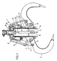
- a grapple 1 intended to be suspended from the boom of a carrier (not shown) constituted for example by a hydraulic shovel.
- the grapple 1 has a vertical cylindrical hollow body 2 on the outer face of which are fixed yokes 3 to each of which is articulated, around an axis 4, a curved arm 5 with a tapered grip end.
- At the upper part of each arm 5 is articulated around an axis 6, the free end of the cylinder of a double-acting hydraulic cylinder 7 whose piston rod 8 is articulated around an axis 8 ′ carried by upper body 2.
- the cylinder 7 On the left-hand side looking at FIG. 1, the cylinder 7 is shown in its extended position corresponding to the closed position of the arms 5 of the grapple, while on the right-hand part looking at this figure, the cylinder 7 is shown at retracted position corresponding to the open position of the arms 5 of the grapple.
- This part of the grapple being well known, it has not been shown in detail, in particular as regards the hydraulic supply of the jacks 7.
- a cylindrical housing 9 closed at its upper end by a bottom 10 and open at its lower end.
- a yoke 11 At the inner face of the bottom 10 is fixed centrally, by means of a yoke 11, the free end of the piston rod 12 of a double-acting hydraulic cylinder 13, the cylinder 14 of which passes through a guide plate 15 At the free end of the cylinder 14 is fixed, by a yoke 16, a peak 17.
- the use of the grab 1 is immediately understood from the above description. From the carrier, the rotation of the seal 18 is controlled to its position ensuring the exit from the jacks 7 and therefore the closing of the arms 5 to grip the car carcass (not shown) to be destroyed.
- the carrier is maneuvered to bring this carcass on the ground, the wheels in the air, position in which it is released by opening the arms 5 of the grab 1.
- the central part of the grab being above, and in the immediate vicinity , from the area of the carcass containing the fuel tank, the operator controls the rotation of the seal 18 to supply the chamber of the jack 13 on the bottom side and forcefully ensure the output of the peak 17 to pierce said tank.
- the seal 18 is controlled by rotation of the supply to the other chamber of the jack 13 to ensure the retraction of the pick 17.
- the carcass is then taken up by the arms 5 of the grab 1 to be deposited in the machine destruction (shears or shredder for example).
- tip of peak 17 may advantageously be made of a material, for example bronze, which does not produce sparks on impact with the sheet iron wall of the element to be drilled, so do not risk creating an explosion and ignition if this element contains a fuel.
Landscapes
- Engineering & Computer Science (AREA)
- Mechanical Engineering (AREA)
- Shovels (AREA)
- Crushing And Pulverization Processes (AREA)
Abstract
Description
- L'invention concerne un grappin pour la manutention de ferrailles et, plus particulièrement un tel grappin utilisable pour la manutention de réservoirs ou autres corps creux susceptibles de contenir des produits inflammables ou dangereux, ou de véhicules équipés de tels réservoirs.
- On sait que, lors de la destruction par cisaillage ou par déchiquetage de produits, en particulier des carcasses de véhicules, susceptibles de contenir des produits dangereux, il est de règle, avant la mise en place de la carcasse à détruire dans la machine (cisaille ou déchiqueteuse) de procéder au perçage du réservoir de carburant afin de permettre au contenu de celui-ci de s'écouler à l'extérieur. On évite ainsi les risques d'une inflammation ou d'une explosion provoquée par exemple par les étincelles engendrées lors du fonctionnement des organes de cisaillage ou de déchiquetage.
- Actuellement ce perçage est effectué manuellement par un opérateur qui, lorsque le véhicule à détruire a été manutentionné par un grappin équipant un engin porteur (tel qu'une pelle hydraulique) pour être posé sur le sol les roues en l'air, escalade le véhicule pour percer le réservoir de carburant de celui-ci au moyen d'un pic ou d'un outil analogue. On comprend qu'une telle opération de perçage manuelle, outre qu'elle présente un danger pour celui qui y procède car le risque d'une explosion ou d'une inflammation immédiate ne peut pas être écarté, entraîne une perte de temps et demande l'intervention d'au moins deux opérateurs, c'est-à-dire le conducteur de l'engin porteur et l'opérateur chargé du perçage.
- La présente invention a pour objet de remédier aux inconvénients mentionnés ci-dessus entraînés par le mode actuel de perçage des réservoirs de carburant des véhicules à détruire, et elle propose à cet effet un dispositif permettant d'effectuer cette opération de perçage dans un laps de temps réduit, en toute sécurité et en faisant appel à une main d'oeuvre minimum.
- Selon l'invention, l'opération de perçage s'effectue sans l'intervention manuelle d'un opérateur particulier, en utilisant le grappin qui sert à la manutention de l'objet à percer et en ne faisant appel qu'au seul opérateur commandant hydrauliquement le fonctionnement dudit grappin.
- A cet effet le grappin selon l'invention comporte, outre ses bras articulés à commande hydraulique servant à la préhension des produits à manutentionner, un organe de perçage en forme de pic disposé à l'intérieur du corps central et relié à un moyen commandant sélectivement un déplacement vertical du pic vers le bas pour procéder à une opération de perçage, et un déplacement du pic vers le haut pour son retour en position rétractée.
- Avantageusement, le pic de perçage est fixé à l'élément mobile d'un vérin hydraulique à double effet dont l'élément fixe est solidaire du corps central du grappin.
- La commande d'arrivée de fluide hydraulique dans l'une ou l'autre des chambres du vérin est obtenue par un distributeur disposé dans la cabine de l'engin porteur, à proximité du distributeur de commande des bras du grappin, un joint tournant à quatre voies assurant sélectivement la commande des bras articulé du grappin ou la course de sortie ou de rétraction de l'organe de perçage.
- On comprend que, pour la destruction d'un objet tel qu'une carcasse de véhicule, l'opérateur conduisant l'engin porteur effectuera de façon conventionnelle la prise de ladite carcasse au moyen du grappin pour la poser sur le sol (après une opération éventuelle de retournement) les roues en l'air. Une fois la carcasse ainsi posée et libérée, l'opérateur maintient le grappin de façon que la partie centrale de celui-ci soit disposée au-dessus de la zone de la carcasse où est logé le réservoir de carburant, puis il commande la sortie du pic dont la force de percussion assure un perçage immédiat du réservoir. Comme aucun opérateur n'est disposé à proximité immédiate de la carcasse, une explosion ou une inflammation accidentelle du carburant contenu dans le réservoir ne pourrait alors avoir de conséquence néfaste pour le personnel.
- Pour bien faire comprendre le dispositif selon l'invention on en décrira ci-après, à titre d'exemple sans caractère limitatif, une forme d'exécution préférée en référence au dessin schématique annexé dans lequel :
- la figure 1 est une vue partiellement en coupe verticale d'un grappin à dispositif de perçage intégré et
- la figure 2 est, à plus grande échelle, une vue perspective avec arrachements de la partie centrale du grappin de la figure 1.
- Au dessin on a représenté un grappin 1 destiné à être suspendu à la flêche d'un engin porteur (non représenté) constitué par exemple par une pelle hydraulique. Le grappin 1 présente un corps vertical cylindrique creux 2 sur la face extérieure duquel sont fixées des chapes 3 à chacune desquelles s'articule, autour d'un axe 4, un bras recourbé 5 à extrémité de préhension effilée. A la partie supérieure de chaque bras 5 est articulé, autour d'un axe 6, l'extrémité libre du cylindre d'un vérin hydraulique 7 à double effet dont la tige de piston 8 est articulée autour d'un axe 8′ porté par la partie supérieure du corps 2.
- Sur la partie de gauche en regardant la figure 1, on a représenté le vérin 7 dans sa position sortie correspondant à la position fermée des bras 5 du grappin, alors que sur la partie de droite en regardant cette figure on a représenté le vérin 7 en position rétractée correspondant à la position ouverte des bras 5 du grappin. Cette partie du grappin étant bien connue, on ne l'a pas représentée en détails, en particulier en ce qui concerne l'alimentation hydraulique des vérins 7.
- A l'intérieur du corps creux 2 est fixé rigidement un logement cylindrique 9, fermé à son extrémité supérieure par un fond 10 et ouvert à son extrémité inférieure. A la face interne du fond 10 est fixée centralement, par l'intermédiaire d'une chape 11, l'extrémité libre de la tige de piston 12 d'un vérin hydraulique à double effet 13 dont le cylindre 14 traverse une plaque de guidage 15. A l'extrémité libre du cylindre 14 est fixée, par une chape 16, un pic 17.
- Un joint tournant 18 à quatre voies, logé à la partie supérieure du corps creux 2, au-dessus du fond 10 du logement 9, commande sélectivement à partir de l'engin porteur soit l'alimentation de l'une ou l'autre chambre des vérins 7 pour assurer l'ouverture ou la fermeture des bras 5 du grappin 1, soit l'alimentation de l'une ou l'autre des chambres du vérin 13 pour assurer la sortie ou la rétraction du pic 17.
- On n'a pas représenté ni décrit en détail les liaisons hydrauliques entre les deux chambres du vérin 13 et le joint tournant 18, mais on comprendra que ces liaisons peuvent être réalisées de toute façon conventionnelle convenable.
- L'utilisation du grappin 1 se comprend immédiatement d'après la description qui précède. A partir de l'engin porteur on commande la rotation du joint 18 jusqu à sa position assurant la sortie des vérins 7 et donc la fermeture des bras 5 pour saisir la carcasse de voiture (non représentée) à détruire. L'engin porteur est manoeuvré pour amener cette carcasse sur le sol, les roues en l'air, position dans laquelle elle est libérée par ouverture des bras 5 du grappin 1. La partie centrale du grappin étant au-dessus, et à proximité immédiate, de la zone de la carcasse contenant le réservoir de carburant, l'opérateur commande la rotation du joint 18 pour alimenter la chambre du vérin 13 côté fond et assurer avec force la sortie du pic 17 pour percer ledit réservoir. Le perçage une fois effectué, on commande par rotation du joint 18 l'alimentation de l'autre chambre du vérin 13 pour assurer la rétraction du pic 17. La carcasse est ensuite reprise par les bras 5 du grappin 1 pour être déposée dans la machine de destruction (cisaille ou déchiqueteuse par exemple).
- On comprendra que la description ci-dessus a été donnée à simple titre d'exemple, sans caractère limitatif, et que des adjonctions ou des modifications constructives pourraient y être apportées sans sortir du cadre de l'invention déterminé par les revendications annexées.
- On comprendra en particulier que la pointe du pic 17 pourra avantageusement être réalisée en un matériau, par exemple du bronze, ne produisant pas d'étincelles lors de l'impact avec la paroi en tôle de fer de l'élément à percer, de façon à ne pas risquer de créer une explosion et une inflammation si cet élément contient un carburant.
Claims (6)
Applications Claiming Priority (2)
| Application Number | Priority Date | Filing Date | Title |
|---|---|---|---|
| FR8911877 | 1989-09-12 | ||
| FR8911877A FR2651763B1 (fr) | 1989-09-12 | 1989-09-12 | Grappin a dispositif de percage integre pour la manutention de ferrailles. |
Publications (2)
| Publication Number | Publication Date |
|---|---|
| EP0418124A1 true EP0418124A1 (fr) | 1991-03-20 |
| EP0418124B1 EP0418124B1 (fr) | 1994-03-16 |
Family
ID=9385342
Family Applications (1)
| Application Number | Title | Priority Date | Filing Date |
|---|---|---|---|
| EP19900402448 Expired - Lifetime EP0418124B1 (fr) | 1989-09-12 | 1990-09-06 | Grappin à dispositif de perçage intégré pour la manutention de ferrailles |
Country Status (4)
| Country | Link |
|---|---|
| EP (1) | EP0418124B1 (fr) |
| DE (1) | DE69007387T2 (fr) |
| ES (1) | ES2054296T3 (fr) |
| FR (1) | FR2651763B1 (fr) |
Cited By (2)
| Publication number | Priority date | Publication date | Assignee | Title |
|---|---|---|---|---|
| EP0890015A4 (fr) * | 1995-11-20 | 2001-02-28 | Action Machinery Company Of Al | Percuteur a grappin |
| CN110127515A (zh) * | 2019-05-22 | 2019-08-16 | 南京禄口起重机械有限公司 | 一种起重机用多瓣抓斗 |
Citations (6)
| Publication number | Priority date | Publication date | Assignee | Title |
|---|---|---|---|---|
| US3064324A (en) * | 1961-06-29 | 1962-11-20 | Morgan Engineering Co | Crane apparatus |
| US3371952A (en) * | 1965-10-24 | 1968-03-05 | Beloit Corp | Log grapple with gripper means |
| CH456862A (de) * | 1965-12-22 | 1968-05-31 | Chepos Zd Y Chemickeho A Potra | Hydraulische Aufhänge-Strippervorrichtung |
| FR2358811A7 (fr) * | 1976-07-15 | 1978-02-10 | Bobin Michel | Grappin destine notamment a la manutention de la ferraille |
| US4466494A (en) * | 1982-08-25 | 1984-08-21 | J. I. Case Company | Implement with gripping arm assembly for a backhoe |
| EP0315547A1 (fr) * | 1987-11-05 | 1989-05-10 | SOLETANCHE Société Anonyme dite: | Benne excavatrice à godets |
-
1989
- 1989-09-12 FR FR8911877A patent/FR2651763B1/fr not_active Expired - Fee Related
-
1990
- 1990-09-06 DE DE1990607387 patent/DE69007387T2/de not_active Expired - Fee Related
- 1990-09-06 EP EP19900402448 patent/EP0418124B1/fr not_active Expired - Lifetime
- 1990-09-06 ES ES90402448T patent/ES2054296T3/es not_active Expired - Lifetime
Patent Citations (6)
| Publication number | Priority date | Publication date | Assignee | Title |
|---|---|---|---|---|
| US3064324A (en) * | 1961-06-29 | 1962-11-20 | Morgan Engineering Co | Crane apparatus |
| US3371952A (en) * | 1965-10-24 | 1968-03-05 | Beloit Corp | Log grapple with gripper means |
| CH456862A (de) * | 1965-12-22 | 1968-05-31 | Chepos Zd Y Chemickeho A Potra | Hydraulische Aufhänge-Strippervorrichtung |
| FR2358811A7 (fr) * | 1976-07-15 | 1978-02-10 | Bobin Michel | Grappin destine notamment a la manutention de la ferraille |
| US4466494A (en) * | 1982-08-25 | 1984-08-21 | J. I. Case Company | Implement with gripping arm assembly for a backhoe |
| EP0315547A1 (fr) * | 1987-11-05 | 1989-05-10 | SOLETANCHE Société Anonyme dite: | Benne excavatrice à godets |
Cited By (2)
| Publication number | Priority date | Publication date | Assignee | Title |
|---|---|---|---|---|
| EP0890015A4 (fr) * | 1995-11-20 | 2001-02-28 | Action Machinery Company Of Al | Percuteur a grappin |
| CN110127515A (zh) * | 2019-05-22 | 2019-08-16 | 南京禄口起重机械有限公司 | 一种起重机用多瓣抓斗 |
Also Published As
| Publication number | Publication date |
|---|---|
| FR2651763B1 (fr) | 1991-12-06 |
| FR2651763A1 (fr) | 1991-03-15 |
| ES2054296T3 (es) | 1994-08-01 |
| DE69007387T2 (de) | 1994-09-29 |
| DE69007387D1 (de) | 1994-04-21 |
| EP0418124B1 (fr) | 1994-03-16 |
Similar Documents
| Publication | Publication Date | Title |
|---|---|---|
| US4461608A (en) | Rear loader container tipper | |
| EP0099819A1 (fr) | Véhicule autopropulsé à bras articulés, réservoir et dispositif d'entraînement débrayable pouvant être montés sur ledit véhicule | |
| JPH05202529A (ja) | ショベルローダの可傾シリンダ | |
| EP0418124B1 (fr) | Grappin à dispositif de perçage intégré pour la manutention de ferrailles | |
| US4412777A (en) | Device for a felling and gripping unit | |
| FR2459779A1 (fr) | Mecanisme de prehension et de levage pour conteneur | |
| FR2946497A1 (fr) | Elagueuse autonome | |
| EP2013421B1 (fr) | Coupleur pour engin de travaux a deverrouillage mixte | |
| FR2822482A1 (fr) | Dispositif de montage d'accessoires de travail en extremite de fleches de machine automotrice et accessoire de travail correspondant | |
| FR2602542A1 (fr) | Machine miniere de creusement ou d'exploitation a coupe partielle | |
| FR2525682A1 (fr) | Outil de deconnexion du connecteur de ligne-guide et procede pour sa mise en oeuvre | |
| KR200355206Y1 (ko) | 유압식원목집게구조 | |
| CH343239A (fr) | Dispositif d'attelage d'une remorque semi-portée à un tracteur | |
| FR2670477A1 (fr) | Grue, en particulier pour la manutention. | |
| EP1053670B1 (fr) | Machine de fauchage | |
| CA2525495A1 (fr) | Fendeur a bois portatif | |
| FR2591249A1 (fr) | Engin de chantier polyvalent porte-outils | |
| CH641864A5 (fr) | Engin de terrassement. | |
| EP0382991A1 (fr) | Crochet de préhension en deux parties pour appareil de halage à bras, notamment pour potence de chargement/déchargement | |
| FR2706920A1 (en) | Clamp for gripping, handling and positioning constructional elements such as kerbstones | |
| EP0384872A1 (fr) | Godet cisailleur interchangeable | |
| EP0671347B1 (fr) | Lève conteneurs à butoir escamotable | |
| EP0295184B1 (fr) | Outil à main à commande hydraulique | |
| FR2759317A1 (fr) | Dispositif de recuperation du carburant contenu dans un reservoir de vehicule automobile | |
| FR2849008A1 (fr) | Pince de prehension universelle permettant de constituer un grappin lorsqu'elle est rapportee sur le bras terminal d'une pelleteuse munie de son godet |
Legal Events
| Date | Code | Title | Description |
|---|---|---|---|
| PUAI | Public reference made under article 153(3) epc to a published international application that has entered the european phase |
Free format text: ORIGINAL CODE: 0009012 |
|
| AK | Designated contracting states |
Kind code of ref document: A1 Designated state(s): BE CH DE ES GB IT LI NL |
|
| 17P | Request for examination filed |
Effective date: 19910827 |
|
| 17Q | First examination report despatched |
Effective date: 19930624 |
|
| GRAA | (expected) grant |
Free format text: ORIGINAL CODE: 0009210 |
|
| AK | Designated contracting states |
Kind code of ref document: B1 Designated state(s): BE CH DE ES GB IT LI NL |
|
| REF | Corresponds to: |
Ref document number: 69007387 Country of ref document: DE Date of ref document: 19940421 |
|
| ITF | It: translation for a ep patent filed | ||
| GBT | Gb: translation of ep patent filed (gb section 77(6)(a)/1977) |
Effective date: 19940621 |
|
| REG | Reference to a national code |
Ref country code: ES Ref legal event code: FG2A Ref document number: 2054296 Country of ref document: ES Kind code of ref document: T3 |
|
| PGFP | Annual fee paid to national office [announced via postgrant information from national office to epo] |
Ref country code: GB Payment date: 19940902 Year of fee payment: 5 |
|
| PGFP | Annual fee paid to national office [announced via postgrant information from national office to epo] |
Ref country code: CH Payment date: 19940905 Year of fee payment: 5 |
|
| PGFP | Annual fee paid to national office [announced via postgrant information from national office to epo] |
Ref country code: ES Payment date: 19940906 Year of fee payment: 5 |
|
| PGFP | Annual fee paid to national office [announced via postgrant information from national office to epo] |
Ref country code: NL Payment date: 19940930 Year of fee payment: 5 |
|
| PGFP | Annual fee paid to national office [announced via postgrant information from national office to epo] |
Ref country code: BE Payment date: 19941012 Year of fee payment: 5 |
|
| PGFP | Annual fee paid to national office [announced via postgrant information from national office to epo] |
Ref country code: DE Payment date: 19941027 Year of fee payment: 5 |
|
| PLBE | No opposition filed within time limit |
Free format text: ORIGINAL CODE: 0009261 |
|
| STAA | Information on the status of an ep patent application or granted ep patent |
Free format text: STATUS: NO OPPOSITION FILED WITHIN TIME LIMIT |
|
| 26N | No opposition filed | ||
| PG25 | Lapsed in a contracting state [announced via postgrant information from national office to epo] |
Ref country code: GB Effective date: 19950906 |
|
| PG25 | Lapsed in a contracting state [announced via postgrant information from national office to epo] |
Ref country code: ES Free format text: LAPSE BECAUSE OF EXPIRATION OF PROTECTION Effective date: 19950907 |
|
| ITTA | It: last paid annual fee | ||
| PG25 | Lapsed in a contracting state [announced via postgrant information from national office to epo] |
Ref country code: LI Effective date: 19950930 Ref country code: CH Effective date: 19950930 Ref country code: BE Effective date: 19950930 |
|
| BERE | Be: lapsed |
Owner name: CIE FRANCAISE DES FERRAILLES Effective date: 19950930 |
|
| PG25 | Lapsed in a contracting state [announced via postgrant information from national office to epo] |
Ref country code: NL Effective date: 19960401 |
|
| GBPC | Gb: european patent ceased through non-payment of renewal fee |
Effective date: 19950906 |
|
| REG | Reference to a national code |
Ref country code: CH Ref legal event code: PL |
|
| PG25 | Lapsed in a contracting state [announced via postgrant information from national office to epo] |
Ref country code: DE Effective date: 19960601 |
|
| NLV4 | Nl: lapsed or anulled due to non-payment of the annual fee |
Effective date: 19960401 |
|
| REG | Reference to a national code |
Ref country code: ES Ref legal event code: FD2A Effective date: 19990601 |
|
| PG25 | Lapsed in a contracting state [announced via postgrant information from national office to epo] |
Ref country code: IT Free format text: LAPSE BECAUSE OF NON-PAYMENT OF DUE FEES;WARNING: LAPSES OF ITALIAN PATENTS WITH EFFECTIVE DATE BEFORE 2007 MAY HAVE OCCURRED AT ANY TIME BEFORE 2007. THE CORRECT EFFECTIVE DATE MAY BE DIFFERENT FROM THE ONE RECORDED. Effective date: 20050906 |