EP0418131A1 - Verschlussvorrichtung mit einer Auflaufzunge - Google Patents
Verschlussvorrichtung mit einer Auflaufzunge Download PDFInfo
- Publication number
- EP0418131A1 EP0418131A1 EP90402476A EP90402476A EP0418131A1 EP 0418131 A1 EP0418131 A1 EP 0418131A1 EP 90402476 A EP90402476 A EP 90402476A EP 90402476 A EP90402476 A EP 90402476A EP 0418131 A1 EP0418131 A1 EP 0418131A1
- Authority
- EP
- European Patent Office
- Prior art keywords
- cam
- elements
- axis
- rotation
- hub
- Prior art date
- Legal status (The legal status is an assumption and is not a legal conclusion. Google has not performed a legal analysis and makes no representation as to the accuracy of the status listed.)
- Granted
Links
- 238000003825 pressing Methods 0.000 claims abstract description 3
- 230000009471 action Effects 0.000 claims description 22
- 230000002269 spontaneous effect Effects 0.000 claims description 7
- 230000002427 irreversible effect Effects 0.000 description 3
- 238000013459 approach Methods 0.000 description 2
- 238000006243 chemical reaction Methods 0.000 description 2
- 238000010586 diagram Methods 0.000 description 2
- 230000005489 elastic deformation Effects 0.000 description 2
- 238000000034 method Methods 0.000 description 2
- 230000036961 partial effect Effects 0.000 description 2
- 230000008569 process Effects 0.000 description 2
- 238000011084 recovery Methods 0.000 description 2
- 241000135309 Processus Species 0.000 description 1
- 239000011324 bead Substances 0.000 description 1
- 230000008901 benefit Effects 0.000 description 1
- 230000006835 compression Effects 0.000 description 1
- 238000007906 compression Methods 0.000 description 1
- 230000008878 coupling Effects 0.000 description 1
- 238000010168 coupling process Methods 0.000 description 1
- 238000005859 coupling reaction Methods 0.000 description 1
- 230000007423 decrease Effects 0.000 description 1
- 230000000694 effects Effects 0.000 description 1
- 229940082150 encore Drugs 0.000 description 1
- 238000005461 lubrication Methods 0.000 description 1
- 238000004519 manufacturing process Methods 0.000 description 1
- 238000012986 modification Methods 0.000 description 1
- 230000004048 modification Effects 0.000 description 1
- 230000035515 penetration Effects 0.000 description 1
- 230000002829 reductive effect Effects 0.000 description 1
- 230000000284 resting effect Effects 0.000 description 1
- 230000002441 reversible effect Effects 0.000 description 1
- 230000002747 voluntary effect Effects 0.000 description 1
- XLYOFNOQVPJJNP-UHFFFAOYSA-N water Substances O XLYOFNOQVPJJNP-UHFFFAOYSA-N 0.000 description 1
Images




Classifications
-
- E—FIXED CONSTRUCTIONS
- E05—LOCKS; KEYS; WINDOW OR DOOR FITTINGS; SAFES
- E05C—BOLTS OR FASTENING DEVICES FOR WINGS, SPECIALLY FOR DOORS OR WINDOWS
- E05C3/00—Fastening devices with bolts moving pivotally or rotatively
- E05C3/12—Fastening devices with bolts moving pivotally or rotatively with latching action
- E05C3/124—Fastening devices with bolts moving pivotally or rotatively with latching action with latch under compression force between its pivot and the striker
-
- B—PERFORMING OPERATIONS; TRANSPORTING
- B64—AIRCRAFT; AVIATION; COSMONAUTICS
- B64G—COSMONAUTICS; VEHICLES OR EQUIPMENT THEREFOR
- B64G1/00—Cosmonautic vehicles
- B64G1/22—Parts of, or equipment specially adapted for fitting in or to, cosmonautic vehicles
- B64G1/64—Systems for coupling or separating cosmonautic vehicles or parts thereof, e.g. docking arrangements
- B64G1/645—Separators
- B64G1/6457—Springs; Shape memory actuators
-
- B—PERFORMING OPERATIONS; TRANSPORTING
- B64—AIRCRAFT; AVIATION; COSMONAUTICS
- B64G—COSMONAUTICS; VEHICLES OR EQUIPMENT THEREFOR
- B64G1/00—Cosmonautic vehicles
- B64G1/22—Parts of, or equipment specially adapted for fitting in or to, cosmonautic vehicles
- B64G1/66—Arrangements or adaptations of apparatus or instruments, not otherwise provided for
-
- Y—GENERAL TAGGING OF NEW TECHNOLOGICAL DEVELOPMENTS; GENERAL TAGGING OF CROSS-SECTIONAL TECHNOLOGIES SPANNING OVER SEVERAL SECTIONS OF THE IPC; TECHNICAL SUBJECTS COVERED BY FORMER USPC CROSS-REFERENCE ART COLLECTIONS [XRACs] AND DIGESTS
- Y10—TECHNICAL SUBJECTS COVERED BY FORMER USPC
- Y10S—TECHNICAL SUBJECTS COVERED BY FORMER USPC CROSS-REFERENCE ART COLLECTIONS [XRACs] AND DIGESTS
- Y10S403/00—Joints and connections
- Y10S403/08—Radially acting cam or eccentric
-
- Y—GENERAL TAGGING OF NEW TECHNOLOGICAL DEVELOPMENTS; GENERAL TAGGING OF CROSS-SECTIONAL TECHNOLOGIES SPANNING OVER SEVERAL SECTIONS OF THE IPC; TECHNICAL SUBJECTS COVERED BY FORMER USPC CROSS-REFERENCE ART COLLECTIONS [XRACs] AND DIGESTS
- Y10—TECHNICAL SUBJECTS COVERED BY FORMER USPC
- Y10T—TECHNICAL SUBJECTS COVERED BY FORMER US CLASSIFICATION
- Y10T24/00—Buckles, buttons, clasps, etc.
- Y10T24/44—Clasp, clip, support-clamp, or required component thereof
- Y10T24/44291—Clasp, clip, support-clamp, or required component thereof including pivoted gripping member
- Y10T24/44368—Pivoted gripping member applies camming force
-
- Y—GENERAL TAGGING OF NEW TECHNOLOGICAL DEVELOPMENTS; GENERAL TAGGING OF CROSS-SECTIONAL TECHNOLOGIES SPANNING OVER SEVERAL SECTIONS OF THE IPC; TECHNICAL SUBJECTS COVERED BY FORMER USPC CROSS-REFERENCE ART COLLECTIONS [XRACs] AND DIGESTS
- Y10—TECHNICAL SUBJECTS COVERED BY FORMER USPC
- Y10T—TECHNICAL SUBJECTS COVERED BY FORMER US CLASSIFICATION
- Y10T292/00—Closure fasteners
- Y10T292/20—Clamps
- Y10T292/225—Cam-operating means
-
- Y—GENERAL TAGGING OF NEW TECHNOLOGICAL DEVELOPMENTS; GENERAL TAGGING OF CROSS-SECTIONAL TECHNOLOGIES SPANNING OVER SEVERAL SECTIONS OF THE IPC; TECHNICAL SUBJECTS COVERED BY FORMER USPC CROSS-REFERENCE ART COLLECTIONS [XRACs] AND DIGESTS
- Y10—TECHNICAL SUBJECTS COVERED BY FORMER USPC
- Y10T—TECHNICAL SUBJECTS COVERED BY FORMER US CLASSIFICATION
- Y10T403/00—Joints and connections
- Y10T403/60—Biased catch or latch
- Y10T403/608—Pivoted
-
- Y—GENERAL TAGGING OF NEW TECHNOLOGICAL DEVELOPMENTS; GENERAL TAGGING OF CROSS-SECTIONAL TECHNOLOGIES SPANNING OVER SEVERAL SECTIONS OF THE IPC; TECHNICAL SUBJECTS COVERED BY FORMER USPC CROSS-REFERENCE ART COLLECTIONS [XRACs] AND DIGESTS
- Y10—TECHNICAL SUBJECTS COVERED BY FORMER USPC
- Y10T—TECHNICAL SUBJECTS COVERED BY FORMER US CLASSIFICATION
- Y10T403/00—Joints and connections
- Y10T403/76—Joints and connections having a cam, wedge, or tapered portion
-
- Y—GENERAL TAGGING OF NEW TECHNOLOGICAL DEVELOPMENTS; GENERAL TAGGING OF CROSS-SECTIONAL TECHNOLOGIES SPANNING OVER SEVERAL SECTIONS OF THE IPC; TECHNICAL SUBJECTS COVERED BY FORMER USPC CROSS-REFERENCE ART COLLECTIONS [XRACs] AND DIGESTS
- Y10—TECHNICAL SUBJECTS COVERED BY FORMER USPC
- Y10T—TECHNICAL SUBJECTS COVERED BY FORMER US CLASSIFICATION
- Y10T74/00—Machine element or mechanism
- Y10T74/21—Elements
- Y10T74/2101—Cams
Definitions
- the present invention relates to a cam locking system for two elements, particularly intended to quickly lock and unlock said elements under difficult conditions and atmospheres, such as those imposed under water or in space (and especially outside of space vehicles).
- a locking system makes it possible to connect one to the other two parts respectively made integral with said elements.
- the invention is intended to simplify as much as possible the maneuvers to be carried out by an operator, as well as to reduce to the maximum the energy necessary for locking and unlocking of said elements (and therefore of said parts which are integral therewith), while providing a locking without play, insensitive to temperature variations and requiring no lubrication.
- the locking system comprising two elements mechanically linked to each other so as not to be able to move apart, as well as a cam mounted to rotate on the first of said elements and having a contact surface pressing a bearing face carried by the second of said elements, is remarkable: - in that said contact surface of said cam has at least approximately a logarithmic spiral profile, while said bearing face is planar; - in that said cam can rotate around a hub, on the axis of which lies the origin of said logarithmic spiral, said hub being rotatably mounted on said first element around an axis of rotation eccentric opposite of said contact surface of said cam, relative to the axis of said hub; - in that elastic means are provided for rotating said cam in a first direction such that said contact surface moves towards said bearing face; - In that said hub carries a stop, which is integral in rotation and which can cause said cam to rotate in a second direction, opposite to the first, said lug does not prevent the rotation of said cam in said first direction under the 'action
- the locking system of the invention is also easily unlockable.
- said contact face of the cam may not be strictly in the form of a logarithmic spiral, provided that the approximation curve of this spiral is such that the geometric properties recalled below are respected by said approximation curve .
- the second of said elements comprises retraction means intended to momentarily push said cam against the action of said elastic means, when said elements are brought together and the contact surface of said cam bears on said bearing face of said second element by spontaneous latching under the action of said elastic means, after having escaped from said retraction means, to lock said elements.
- the close locking position of said elements is determined by a stop system.
- the extreme position that said cam can take under the action of said elastic means can be delimited by a stop.
- said first and second elements are hinged to each other at their ends respectively opposite to said cam and to said bearing face, about an axis parallel to the axis of rotation of said cam.
- This articulation of said first and second elements can constitute a non-removable connection between them.
- the articulation of said first and second elements can form a removable connection.
- the articulation between said first and second elements be constituted by a fixed shaft integral with an element and by surfaces V-bearing integral with the other element.
- one of the elements is integral with V-shaped bearing surfaces in a direction orthogonal to said axis of rotation between said elements, while the other element has a stop capable of coming to bear against said V-shaped bearing surfaces when said elements are in close position .
- said stop system delimiting the close position of the two elements is provided to delimit several different close positions of the two elements
- said second element comprises several retraction means and several distinct bearing faces and , for each close position, said cam is in abutment by its contact face against one of said bearing faces.
- FIG. 1 there is shown a flat cam 1, which is capable of rotating about an axis 2 orthogonal to its plane and whose contact face 3 is a portion of a logarithmic spiral 4 whose origin is on the axis 2.
- the cam 1 bears on a flat surface 5, at point 6.
- cam 1 four important properties result: - if the value of the angle ⁇ is determined so that its tangent is less than that of the friction angle (generally designated by ⁇ in mechanics), the reaction R at the fulcrum 6 is at inside the friction cone, so that the cam is balanced by bracing; - This stable and irreversible support is obtained whatever the point 6 or 6 ′ of the cam 1 which is in contact with the surface 5; - if, in a mechanical assembly, the distance d separating the axis of rotation 2 from the surface 5 is variable, for example due to vibrations, variations in the applied loads or for reasons of manufacturing tolerances or temperature variations , he is possible to compensate for these variations in the distance d and to find, despite themselves, a stable and irreversible support for the cam 1 on the surface 5, by rotation of the latter, since the spokes 8.8 ′ have different lengths; and - if a stable support being obtained at 6 for a given radius 8, the cam 1 and / or the support surface 5 are subjected
- the present invention takes advantage of these features.
- FIGS. 2 to 12 we find the cam 1, its axis of rotation 2, its logarithmic contact face 3, as well as the planar bearing surface 5. More particularly, in these FIGS. 2 to 12, the mounting of the cam 1 is similar to that of the embodiment illustrated in FIGS. 22 to 29.
- the cam 1 is rotatably mounted around a hub 22 of axis 2, itself rotatably mounted on a first element 10 (see FIGS. 13 to 29) by means of end journals 20, as shown in FIG. 15.
- the axis 9 of the end journals 20 is eccentric relative to the axis 2, in the direction opposite to the logarithmic contact face 3.
- the cam 1 is pressed in the direction of the arrow f1 by elastic means 29, 55 (see FIGS. 13 to 29), in the direction of the planar bearing surface 5. This is secured to a second element 11, as will be explained below.
- a stud 26, integral with the hub 22 and the end journals 20, can cooperate with an abutment face 27 provided on said cam 1.
- the elements 10 and 11 are mechanically linked to each other, for example in rotation, so that they cannot be moved apart from one another when the contact face 3 is in locking support on the planar support surface 5.
- the elements 10 and 11 are in a close relative position, such that the front end face 42 of the cam 1 is in abutment against the front face 39 (retraction means) of the element 11.
- the face 39 prevents the elastic means 29, 55 from turning the cam 1 fully in the direction f1, that is to say that then said elastic means 29, 55 are bandaged. If the elements 10 and 11 are moved so as to tend to move them away from one another, the end face 32 of the cam 1 remaining in abutment against the face 39 of the element 11, it happens a moment when the cam 1 escapes the retraction action of said face 29 (see FIG. 3).
- the cam 1 In this position, the cam 1 is detached from the element 11, but has not yet rotated in the direction f2.
- the rotation of the cam 1 in the direction f2 can only start from the moment when the pin 26 being brought into contact with the stop 27 (see FIG. 9), the voluntary rotation of the hub 22 and of the pins 20 is continued in the direction f2 (see Figure 10).
- the stud 26, bearing on the stop 27, then pushes the cam 1 in the direction f2, by rotating it around the hub 22 (see FIG. 11). Continuation of this rotation then causes the cam 1 to escape from the bearing surface 5 (see FIG. 12).
- the detachment d of the cam 1 (FIG. 8) preceding the support of the stud 26 on the stop 27 constitutes a safety margin.
- the self-locking assembly system allows the assembly with reversible locking of its two separate elements 10 and 11.
- the element 10 is mounted secured to the structure 12 of a spacecraft, on the outside of the latter and the element 13 is secured to a structure 13 (for example an antenna), which must be fixed to said spacecraft.
- the element 10 comprises a thick non-deformable plate 14 from which stand pairs of legs 13 and 18 arranged at opposite ends of said plate (see also FIG. 14). Between the legs 15 is mounted a fixed shaft 17. The upper part of the legs 15 is shaped as bevels 18, forming an opening (of angle ⁇ ) diverging outward for the space between said legs 15. Plumb with the fixed shaft 17, in the middle position thereof, a cylindrical stud 19 is provided, integral with the plate 10.
- the rotary shaft 20 with an axis 20 ′ (see also FIGS. 15 and 16) is mounted on a bearing between the lugs 16.
- the rotary shaft 20 is parallel to the fixed shaft 17 and it can be actuated by a handle 21.
- the central part 22 of the rotary shaft 20 is eccentric relative to said shaft, to form a hub for the cam 1.
- the shaft 20 is mounted the cam 1 so that the axis 2 of the said cam coincides with the axis of the said eccentric part 22.
- the rotary shaft 20 forms eccentric end journals for the central hub 22.
- the rotation of the cam 1 relative to the hub 22 is delimited by a stop 23 secured to the cam 1 and capable of cooperating with supports 24 and 25, secured to the legs 16.
- the stud 26 integral with the rotary shaft 20 can cooperate respectively with abutment faces 27, 28 carried by said cam, so that said cam can be turned by action on the handle 21, as indicated above.
- a spring system 29 and a connecting rod 30 pulls the cam 1 in the direction of the fixed shaft 17.
- the spring system 29 applies the stop 23 against the support 24, so that the cam 1 occupies its extreme tilting position d waiting in the direction of the shaft 17, and the handle 21 occupies a position such that the stud 26 is located between the abutment faces 27 and 28, for example equidistant from the latter.
- a stop 31 is provided integral with the plate 14, between the pairs of legs 15 and 16.
- the element 11 also comprises a thick non-deformable plate 32, one end of which comprises supports 33 in the form of a V defining a support line transverse to said plate, as well as a notch 34, also in the form of a V, formed in the thickness of said plate.
- the relative positions of the supports 33 and the notch 34 are such that the fixed shaft 17 and the stud 19 can be brought simultaneously and respectively into support between the V faces of said supports 33 and the notch 36.
- the supports in V 33 are closed by elastic blades 35, integral with said plate at their end opposite to said supports, by screws 36.
- the elastic blades 35 are extended beyond by curved parts 37, moving away from plate 32.
- the plate has bevels 38 in opposite directions, so that between the bent elastic parts 37 and the bevels 38 are formed aligned ves, defining a transverse line to the plate 32.
- the plate 32 has a rounded end face 39, provided with a longitudinal slot 40, the width of which is greater than the thickness of the cam 1 and the bottom of which is flat to form the planar bearing surface 5, intended to cooperate with the logarithmic contact face 3 of said cam 1.
- a stop 41 is provided under the plate 32.
- the cam 1 continues to be pushed back by the rounded end portion 39 of the element 11, until the slot 40 is located opposite said cam 1.
- the cam 1 escapes the action of pushing back the rounded end part 39 and enters the slot 40 (arrow f1), its contact face 3 resting on the flat surface 5 serving as a bottom for said slot 40.
- the elements 10 and 11 are then in the relative position shown in FIGS. 18 and 19, in which: - The fixed shaft 17 is in contact with the supports 33 in the form of a V; - The stud 19 is in contact with the V-shaped faces of the notch 34; - The stops 31 and 41 are in contact with each other.
- the elements 10 and 11 are automatically locked relative to each other. It will be noted that the locking position thus reached depends only on the clearances between the elements 10 and 11, which are absorbed by the cam. In addition, this locking position is safe because the recovery: - efforts transverse to the fixed shaft 17 is obtained by the cooperation of the supports 33 and said fixed shaft 17; - forces orthogonal to the elements 10 and 11 is produced by the fixed shaft 17, the supports 33, the cam 1, the surface 5 and the stops 31 and 41; - forces parallel to the fixed shaft 17 is supported by the stud 19 and the notch 34; - Torques around an axis transverse to the fixed shaft 17, and around an axis orthogonal to the elements 10 and 11 is obtained by the shaft 17 and the supports 33; - the torque around an axis parallel to the fixed shaft 17 is provided by the stops 31, 41, the cam 1, and the surface 5.
- the locking position only depends on the clearances and not on the position of the handle 21 and that the unlocking is carried out from any relative position of the cam 1 relative to the support surface 5.
- FIGS. 22 to 29 we find the same elements as in the embodiment of FIGS. 13 to 21, but with the following modifications: -
- the fixed hinge shaft 17, integral with the element 10 is mounted captive in the element 11, so that said elements 10 and 11 are no longer removable; the logarithmic cam 1, the control shaft 20, 22, the stud 23, the support 24 and the handle 21 are mounted on the element 11 and no longer on the element 10;
- the stop 31, integral with the element 10, is integral with a tilting assembly 50 subjected to the action of a spring 51 (see FIG. 28), so as to be able to occupy a position 31 or a position 31 ′ respectively shown in solid line and in broken line in FIG. 22 and preset in the factory.
- the spring 51 In the position 31 of the stop, the spring 51 is banded and the rocking assembly 50 is held by a pin 52. If the pin 52 is pulled, the spring 51 causes the stop to tip into position 31 ′; -
- the element 10 comprises a shoe 53 comprising two distinct bearing surfaces 5 and 5 ′; -
- the means for retracting the ramp 1 comprise a rounded end 39 and an inclined plane 54, respectively carried by said shoe 53; -
- the centering and locking stud 19 secured to the plate 14 is replaced by a bead 19 secured to the fixed shaft 17;
- the spring system 29 and the connecting rod 30 are replaced by helical springs 55, mounted on the shaft 20,22; -
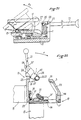
- the security system 56 is actuated, so that the pin 57 is retracted and that the handle 21 can rotate in the direction F2, opposite to the direction F. Thanks to the eccentricity of the axis of rotation 2 of the cam 1, the latter is released from its bearing face 5. The clearance is complete if the rotation of the handle 21 is continued in the direction F2 (see the FIG. 26), so that it is then possible to return the element 11 to its initial position in FIG. 22.
- the stop 31 takes the least projecting position 31 ′ under the action of the spring 51 and the extreme edge 42 can come into contact of the inclined plane 54 after resetting the handle 21 ( Figures 27 and 28). Continuing this movement, one can spontaneously anchor the contact face 3 of the cam behind the second bearing face 5 ′ (figure 29). It is then possible to unlock the two elements 10 and 11 (by rotation of the handle 21 in the direction F2 after retraction of the pin 57) according to processes similar to those described above.
Landscapes
- Engineering & Computer Science (AREA)
- Remote Sensing (AREA)
- Aviation & Aerospace Engineering (AREA)
- Mechanical Engineering (AREA)
- Clamps And Clips (AREA)
- Pivots And Pivotal Connections (AREA)
- Snaps, Bayonet Connections, Set Pins, And Snap Rings (AREA)
Applications Claiming Priority (2)
| Application Number | Priority Date | Filing Date | Title |
|---|---|---|---|
| FR8911898 | 1989-09-12 | ||
| FR8911898A FR2651843B1 (fr) | 1989-09-12 | 1989-09-12 | Systeme de verrouillage a came. |
Publications (2)
| Publication Number | Publication Date |
|---|---|
| EP0418131A1 true EP0418131A1 (de) | 1991-03-20 |
| EP0418131B1 EP0418131B1 (de) | 1993-11-18 |
Family
ID=9385356
Family Applications (1)
| Application Number | Title | Priority Date | Filing Date |
|---|---|---|---|
| EP90402476A Expired - Lifetime EP0418131B1 (de) | 1989-09-12 | 1990-09-10 | Verschlussvorrichtung mit einer Auflaufzunge |
Country Status (7)
| Country | Link |
|---|---|
| US (1) | US5108216A (de) |
| EP (1) | EP0418131B1 (de) |
| JP (1) | JPH03121301A (de) |
| CA (1) | CA2024412A1 (de) |
| DE (1) | DE69004646T2 (de) |
| ES (1) | ES2048462T3 (de) |
| FR (1) | FR2651843B1 (de) |
Cited By (3)
| Publication number | Priority date | Publication date | Assignee | Title |
|---|---|---|---|---|
| FR2696813A1 (fr) * | 1992-10-14 | 1994-04-15 | Alcatel Espace | Ensemble de verrouillage rapide et de centrage d'une charge prévue flottante dans une enceinte. |
| FR2721583A1 (fr) * | 1994-06-27 | 1995-12-29 | Aerospatiale | Dispositif de gerbage à déclenchement mécanique pour engin spatial. |
| FR2722761A1 (fr) * | 1994-07-20 | 1996-01-26 | Aerospatiale | Systeme pour deployer/replier deux elements, avec verrouillage par came desdits elements deployes |
Families Citing this family (53)
| Publication number | Priority date | Publication date | Assignee | Title |
|---|---|---|---|---|
| CA2094569C (en) * | 1992-05-08 | 1998-07-14 | Dennis H. Vaders | Press die clamp |
| KR0160847B1 (ko) * | 1995-02-20 | 1998-12-01 | 구자홍 | 칼라브라운관용 마그네트 구조체 |
| DE19746739A1 (de) * | 1997-10-23 | 1999-05-06 | Gva Ges Fuer Verfahren Der Abw | Vorrichtung zum Positionieren und Befestigen einer Baugruppe |
| US6158729A (en) * | 1998-11-24 | 2000-12-12 | The United States Of America As Represented By The Administrator Of The National Aeronautics And Space Administration | Compact, stiff, remotely-actuable quick-release clamp |
| DE10037805B4 (de) | 2000-08-03 | 2017-04-06 | Wolfcraft Gmbh | Traggestell, insbesondere Rollenbock |
| DE10312935B4 (de) * | 2003-03-22 | 2006-01-26 | Wolfcraft Gmbh | Stützbock |
| DE10319067A1 (de) * | 2003-04-28 | 2004-11-18 | Wolfcraft Gmbh | Traggestell |
| US8220611B2 (en) * | 2004-06-24 | 2012-07-17 | Mei, Inc. | Currency mechanism retention |
| WO2006050266A2 (en) | 2004-10-29 | 2006-05-11 | Boa Technology, Inc. | Reel based closure system |
| AT502938A1 (de) * | 2004-11-18 | 2007-06-15 | Blum Gmbh Julius | Stellantrieb zum bewegen einer klappe eines möbels |
| EP2076224B1 (de) | 2006-09-12 | 2016-08-24 | Boa Technology, Inc. | Verschlusssystem für gurte, schutzkleidung und ähnliche artikel |
| JP5709526B2 (ja) | 2008-01-18 | 2015-04-30 | ボア テクノロジー,インコーポレイテッド | 閉塞システム |
| DE112011100318B4 (de) | 2010-01-21 | 2023-04-20 | Boa Technology, Inc. | Führungen für Schnürsysteme |
| JP5479145B2 (ja) * | 2010-02-18 | 2014-04-23 | 三菱重工業株式会社 | 結合分離装置、結合分離システム、及び結合分離方法 |
| US9375053B2 (en) | 2012-03-15 | 2016-06-28 | Boa Technology, Inc. | Tightening mechanisms and applications including the same |
| KR102566159B1 (ko) | 2010-04-30 | 2023-08-16 | 보아 테크놀러지, 인크. | 릴 기반 끈 조임 시스템 |
| US10070695B2 (en) | 2010-04-30 | 2018-09-11 | Boa Technology Inc. | Tightening mechanisms and applications including the same |
| KR20130103705A (ko) | 2010-07-01 | 2013-09-24 | 보아 테크놀러지, 인크. | 끈 가이드 |
| US8997315B2 (en) * | 2011-01-19 | 2015-04-07 | Nite Ize, Inc. | Self-locking clip systems and methods |
| US9101181B2 (en) | 2011-10-13 | 2015-08-11 | Boa Technology Inc. | Reel-based lacing system |
| US9145096B2 (en) * | 2011-12-13 | 2015-09-29 | Water Works Manufacturing, Llc | System for attaching an accessory such as a snowplow to a vehicle |
| US9179729B2 (en) | 2012-03-13 | 2015-11-10 | Boa Technology, Inc. | Tightening systems |
| DE112013005273B4 (de) | 2012-11-02 | 2017-08-24 | Boa Technology, Inc. | Kupplungsteile für Verschlussvorrichtungen und -systeme |
| WO2014074645A2 (en) | 2012-11-06 | 2014-05-15 | Boa Technology Inc. | Devices and methods for adjusting the fit of footwear |
| EP3607845B1 (de) | 2013-01-28 | 2022-11-09 | Boa Technology Inc. | Riemenfixieranordnung und system |
| US10702409B2 (en) | 2013-02-05 | 2020-07-07 | Boa Technology Inc. | Closure devices for medical devices and methods |
| EP2964048B1 (de) | 2013-03-05 | 2019-08-28 | Boa Technology Inc. | Systeme und vorrichtungen zum automatischen schliessen von medizinischen vorrichtungen |
| US10251451B2 (en) | 2013-03-05 | 2019-04-09 | Boa Technology Inc. | Closure devices including incremental release mechanisms and methods therefor |
| WO2014165541A2 (en) | 2013-04-01 | 2014-10-09 | Boa Technology Inc. | Methods and devices for retrofitting footwear to include a reel based closure system |
| FI12797Y1 (en) | 2013-06-05 | 2020-10-16 | Boa Tech Inc | Roller-based closure device for tightening an object |
| US10076160B2 (en) | 2013-06-05 | 2018-09-18 | Boa Technology Inc. | Integrated closure device components and methods |
| WO2015003079A1 (en) | 2013-07-02 | 2015-01-08 | Boa Technology Inc. | Tension limiting mechanisms for closure devices and methods therefor |
| WO2015006616A1 (en) | 2013-07-10 | 2015-01-15 | Boa Technology Inc. | Closure devices including incremental release mechanisms and methods therefor |
| WO2015035257A2 (en) | 2013-09-05 | 2015-03-12 | Boa Technology Inc. | Alternative lacing guides for tightening mechanisms and methods therefor |
| KR102297325B1 (ko) | 2013-09-13 | 2021-09-03 | 보아 테크놀러지, 인크. | 릴 기반 폐쇄 장치 및 그에 따른 방법 |
| KR101895140B1 (ko) | 2013-11-18 | 2018-09-04 | 보아 테크놀러지, 인크. | 보철 및 장구의 자동 폐쇄를 제공하기 위한 방법 및 장치 |
| USD835976S1 (en) | 2014-01-16 | 2018-12-18 | Boa Technology Inc. | Coupling member |
| US20160058127A1 (en) | 2014-08-28 | 2016-03-03 | Boa Technology Inc. | Devices and methods for enhancing the fit of boots and other footwear |
| WO2016057697A1 (en) | 2014-10-07 | 2016-04-14 | Boa Technology Inc. | A tension adjustment mechanism and a method for adjusting the fit of a shoe |
| USD835898S1 (en) | 2015-01-16 | 2018-12-18 | Boa Technology Inc. | Footwear lace tightening reel stabilizer |
| US10004297B2 (en) | 2015-10-15 | 2018-06-26 | Boa Technology Inc. | Lacing configurations for footwear |
| US10499709B2 (en) | 2016-08-02 | 2019-12-10 | Boa Technology Inc. | Tension member guides of a lacing system |
| KR102822775B1 (ko) | 2016-12-09 | 2025-06-20 | 보아 테크놀러지, 인크. | 릴 기반의 폐쇄 시스템 |
| US10543630B2 (en) | 2017-02-27 | 2020-01-28 | Boa Technology Inc. | Reel based closure system employing a friction based tension mechanism |
| US11357279B2 (en) | 2017-05-09 | 2022-06-14 | Boa Technology Inc. | Closure components for a helmet layer and methods for installing same |
| US12396520B2 (en) | 2017-07-18 | 2025-08-26 | Boa Technology Inc. | Configurations for footwear employing reel based closure systems |
| US10772384B2 (en) | 2017-07-18 | 2020-09-15 | Boa Technology Inc. | System and methods for minimizing dynamic lace movement |
| WO2020160421A1 (en) | 2019-02-01 | 2020-08-06 | Boa Technology Inc. | Reel based closure devices for tightening a ski boot |
| CN118907988A (zh) | 2019-05-01 | 2024-11-08 | Boa科技股份有限公司 | 基于卷轴的闭合系统 |
| CN112298611B (zh) * | 2020-09-30 | 2022-01-21 | 北京空间飞行器总体设计部 | 一种适用于太空出舱活动的手持式对接机构 |
| CN113998152B (zh) * | 2021-03-03 | 2025-05-27 | 东方空间技术(山东)有限公司 | 星箭分离装置 |
| CN114056604B (zh) * | 2021-11-29 | 2022-06-07 | 北京卫星环境工程研究所 | 一种在轨维修用的移动扶手 |
| EP4588811A1 (de) * | 2024-01-16 | 2025-07-23 | Aciturri Engineering, S.L. | System zur befestigung und trennung von strukturen |
Citations (5)
| Publication number | Priority date | Publication date | Assignee | Title |
|---|---|---|---|---|
| GB191217149A (en) * | 1912-07-23 | 1913-05-15 | Percy Alliott Smithurst | Improvements in Latch and other like Fastenings. |
| US2143575A (en) * | 1937-01-09 | 1939-01-10 | Stanley Works | Spring catch |
| FR971458A (fr) * | 1948-09-09 | 1951-01-17 | Mecanis A G | Dispositif de fixation des pièces sur un établi |
| GB1242639A (en) * | 1968-02-23 | 1971-08-11 | Arthur Frederick John Pratt | Improvements in or relating to latches for gates or the like |
| EP0146996A2 (de) * | 1983-12-23 | 1985-07-03 | Constructions Electro-Mecaniques D'amiens | Waschmaschine mit einer Tür mit mechanischer Sperrvorrichtung |
Family Cites Families (7)
| Publication number | Priority date | Publication date | Assignee | Title |
|---|---|---|---|---|
| US736053A (en) * | 1902-12-08 | 1903-08-11 | Tulley B Armstrong | Hatch-fastener. |
| US945081A (en) * | 1909-06-18 | 1910-01-04 | Sellers William & Co Inc | Tool-holder. |
| US1511704A (en) * | 1921-06-11 | 1924-10-14 | Buck Ainsworth | Window-cleaner's safety device |
| US2060214A (en) * | 1935-12-17 | 1936-11-10 | Sherman B Hitchens | Pipe handling apparatus |
| US2553144A (en) * | 1947-07-24 | 1951-05-15 | Edward E Olsen | Lock and slide for screen or storm windows |
| US3565448A (en) * | 1969-04-18 | 1971-02-23 | United Aircraft Corp | Adjustable sealing and fixturing device |
| US4274666A (en) * | 1979-11-05 | 1981-06-23 | Peck Almo E | Lock for sliding windows and doors |
-
1989
- 1989-09-12 FR FR8911898A patent/FR2651843B1/fr not_active Expired - Fee Related
-
1990
- 1990-08-31 CA CA002024412A patent/CA2024412A1/fr not_active Abandoned
- 1990-09-10 DE DE90402476T patent/DE69004646T2/de not_active Expired - Fee Related
- 1990-09-10 EP EP90402476A patent/EP0418131B1/de not_active Expired - Lifetime
- 1990-09-10 ES ES90402476T patent/ES2048462T3/es not_active Expired - Lifetime
- 1990-09-10 US US07/580,112 patent/US5108216A/en not_active Expired - Fee Related
- 1990-09-12 JP JP2240184A patent/JPH03121301A/ja active Pending
Patent Citations (5)
| Publication number | Priority date | Publication date | Assignee | Title |
|---|---|---|---|---|
| GB191217149A (en) * | 1912-07-23 | 1913-05-15 | Percy Alliott Smithurst | Improvements in Latch and other like Fastenings. |
| US2143575A (en) * | 1937-01-09 | 1939-01-10 | Stanley Works | Spring catch |
| FR971458A (fr) * | 1948-09-09 | 1951-01-17 | Mecanis A G | Dispositif de fixation des pièces sur un établi |
| GB1242639A (en) * | 1968-02-23 | 1971-08-11 | Arthur Frederick John Pratt | Improvements in or relating to latches for gates or the like |
| EP0146996A2 (de) * | 1983-12-23 | 1985-07-03 | Constructions Electro-Mecaniques D'amiens | Waschmaschine mit einer Tür mit mechanischer Sperrvorrichtung |
Cited By (6)
| Publication number | Priority date | Publication date | Assignee | Title |
|---|---|---|---|---|
| FR2696813A1 (fr) * | 1992-10-14 | 1994-04-15 | Alcatel Espace | Ensemble de verrouillage rapide et de centrage d'une charge prévue flottante dans une enceinte. |
| FR2721583A1 (fr) * | 1994-06-27 | 1995-12-29 | Aerospatiale | Dispositif de gerbage à déclenchement mécanique pour engin spatial. |
| FR2722761A1 (fr) * | 1994-07-20 | 1996-01-26 | Aerospatiale | Systeme pour deployer/replier deux elements, avec verrouillage par came desdits elements deployes |
| EP0694474A1 (de) * | 1994-07-20 | 1996-01-31 | Aerospatiale Societe Nationale Industrielle | System zum Entfalten/Falten zweier Elemente mit einer Nockenverriegelung der entfalteten Elemente |
| WO1996002418A1 (fr) * | 1994-07-20 | 1996-02-01 | Aerospatiale Societe Nationale Industrielle | Systeme pour deployer/replier deux elements, avec verrouillage par came desdits elements deployes |
| US5699698A (en) * | 1994-07-20 | 1997-12-23 | Aerospatiale Societe Nationale Industrielle | System for extending or retracting two members and cam-locking the members in the extended position |
Also Published As
| Publication number | Publication date |
|---|---|
| FR2651843A1 (fr) | 1991-03-15 |
| US5108216A (en) | 1992-04-28 |
| ES2048462T3 (es) | 1994-03-16 |
| EP0418131B1 (de) | 1993-11-18 |
| DE69004646T2 (de) | 1994-04-14 |
| CA2024412A1 (fr) | 1991-03-13 |
| DE69004646D1 (de) | 1993-12-23 |
| FR2651843B1 (fr) | 1991-12-20 |
| JPH03121301A (ja) | 1991-05-23 |
Similar Documents
| Publication | Publication Date | Title |
|---|---|---|
| EP0418131B1 (de) | Verschlussvorrichtung mit einer Auflaufzunge | |
| EP0434825B1 (de) | Schnell montierbare mutter | |
| EP0157666A1 (de) | Rotationspotentiometer, insbesondere für Winkelpositionsmessung | |
| FR2746065A1 (fr) | Appui-tete pour siege de vehicule automobile | |
| EP0082761A1 (de) | Kraftfahrzeugtürschloss | |
| FR2627150A1 (fr) | Articulation pour le deploiement en deux etapes d'un panneau solaire | |
| EP0694474B1 (de) | System zum Entfalten/Falten zweier Elemente mit einer Nockenverriegelung der entfalteten Elemente | |
| FR2865492A1 (fr) | Ensemble de verrouillage, notamment d'un element mobile de fermeture, et combinaison l'utilisant | |
| FR2852346A1 (fr) | Ensemble de verrouillage pour un element mobile de fermeture, et combinaison le comprenant | |
| EP1291478B1 (de) | Schloss mit Universalaufstellung | |
| FR2776325A1 (fr) | Verrou a debrayage axial perfectionne pour un mecanisme de serrure de vehicule automobile | |
| EP0404609B1 (de) | Türschloss und -beschlag für Panikfälle | |
| EP0597764B1 (de) | Fensterheber für ein Kraftfahrzeug | |
| FR2806531A1 (fr) | Dispositif de fixation d'une batterie d'accumulateurs | |
| EP0469939B1 (de) | Vorrichtung zum Verbinden zweier Gegenstände mit mehreren Befestigungspunkten | |
| CH629106A5 (fr) | Fixation de securite pour ski. | |
| EP2079629A2 (de) | Vorrichtung zur befestigung eines ersten teilsatzes an einem zweiten teilsatz eines kraftfahrzeugs | |
| FR2697566A1 (fr) | Serrure à pêne basculant. | |
| FR2789427A1 (fr) | Poignee de vehicule automobile | |
| FR2772625A1 (fr) | Dispositif de fixation rapide de chaussure sur planche de surf | |
| EP0444972B1 (de) | Schloss mit einem Stator und einem frei rotierenden im Stator montierten Rotor | |
| EP0354107B1 (de) | Befestigungsvorrichtung zum schnellen Andocken und Lösen einer Struktur | |
| CH656319A5 (fr) | Fixation de securite pour ski. | |
| WO2000053940A1 (fr) | Dispositif de fixation rapide et universelle | |
| EP0940529A1 (de) | Doppelsicherheitszylinder |
Legal Events
| Date | Code | Title | Description |
|---|---|---|---|
| PUAI | Public reference made under article 153(3) epc to a published international application that has entered the european phase |
Free format text: ORIGINAL CODE: 0009012 |
|
| AK | Designated contracting states |
Kind code of ref document: A1 Designated state(s): BE DE ES GB IT NL SE |
|
| 17P | Request for examination filed |
Effective date: 19910404 |
|
| 17Q | First examination report despatched |
Effective date: 19920521 |
|
| GRAA | (expected) grant |
Free format text: ORIGINAL CODE: 0009210 |
|
| AK | Designated contracting states |
Kind code of ref document: B1 Designated state(s): BE DE ES GB IT NL SE |
|
| GBT | Gb: translation of ep patent filed (gb section 77(6)(a)/1977) |
Effective date: 19931117 |
|
| REF | Corresponds to: |
Ref document number: 69004646 Country of ref document: DE Date of ref document: 19931223 |
|
| ITF | It: translation for a ep patent filed | ||
| REG | Reference to a national code |
Ref country code: ES Ref legal event code: FG2A Ref document number: 2048462 Country of ref document: ES Kind code of ref document: T3 |
|
| PGFP | Annual fee paid to national office [announced via postgrant information from national office to epo] |
Ref country code: SE Payment date: 19940818 Year of fee payment: 5 |
|
| PGFP | Annual fee paid to national office [announced via postgrant information from national office to epo] |
Ref country code: DE Payment date: 19940822 Year of fee payment: 5 |
|
| PGFP | Annual fee paid to national office [announced via postgrant information from national office to epo] |
Ref country code: GB Payment date: 19940831 Year of fee payment: 5 |
|
| PGFP | Annual fee paid to national office [announced via postgrant information from national office to epo] |
Ref country code: ES Payment date: 19940906 Year of fee payment: 5 |
|
| PLBE | No opposition filed within time limit |
Free format text: ORIGINAL CODE: 0009261 |
|
| STAA | Information on the status of an ep patent application or granted ep patent |
Free format text: STATUS: NO OPPOSITION FILED WITHIN TIME LIMIT |
|
| PGFP | Annual fee paid to national office [announced via postgrant information from national office to epo] |
Ref country code: NL Payment date: 19940930 Year of fee payment: 5 |
|
| PGFP | Annual fee paid to national office [announced via postgrant information from national office to epo] |
Ref country code: BE Payment date: 19941108 Year of fee payment: 5 |
|
| 26N | No opposition filed | ||
| EAL | Se: european patent in force in sweden |
Ref document number: 90402476.7 |
|
| PG25 | Lapsed in a contracting state [announced via postgrant information from national office to epo] |
Ref country code: GB Effective date: 19950910 |
|
| PG25 | Lapsed in a contracting state [announced via postgrant information from national office to epo] |
Ref country code: SE Effective date: 19950911 Ref country code: ES Free format text: LAPSE BECAUSE OF THE APPLICANT RENOUNCES Effective date: 19950911 |
|
| PG25 | Lapsed in a contracting state [announced via postgrant information from national office to epo] |
Ref country code: BE Effective date: 19950930 |
|
| BERE | Be: lapsed |
Owner name: AEROSPATIALE SOC. NATIONALE INDUSTRIELLE Effective date: 19950930 |
|
| PG25 | Lapsed in a contracting state [announced via postgrant information from national office to epo] |
Ref country code: NL Effective date: 19960401 |
|
| GBPC | Gb: european patent ceased through non-payment of renewal fee |
Effective date: 19950910 |
|
| PG25 | Lapsed in a contracting state [announced via postgrant information from national office to epo] |
Ref country code: DE Effective date: 19960601 |
|
| NLV4 | Nl: lapsed or anulled due to non-payment of the annual fee |
Effective date: 19960401 |
|
| EUG | Se: european patent has lapsed |
Ref document number: 90402476.7 |
|
| REG | Reference to a national code |
Ref country code: ES Ref legal event code: FD2A Effective date: 19991007 |
|
| PG25 | Lapsed in a contracting state [announced via postgrant information from national office to epo] |
Ref country code: IT Free format text: LAPSE BECAUSE OF NON-PAYMENT OF DUE FEES;WARNING: LAPSES OF ITALIAN PATENTS WITH EFFECTIVE DATE BEFORE 2007 MAY HAVE OCCURRED AT ANY TIME BEFORE 2007. THE CORRECT EFFECTIVE DATE MAY BE DIFFERENT FROM THE ONE RECORDED. Effective date: 20050910 |