EP0418180A1 - Verfahren zum Aufzeichnen und Wiedergeben von Fernsehsignalen mit hoher Auflösung - Google Patents
Verfahren zum Aufzeichnen und Wiedergeben von Fernsehsignalen mit hoher Auflösung Download PDFInfo
- Publication number
- EP0418180A1 EP0418180A1 EP90460032A EP90460032A EP0418180A1 EP 0418180 A1 EP0418180 A1 EP 0418180A1 EP 90460032 A EP90460032 A EP 90460032A EP 90460032 A EP90460032 A EP 90460032A EP 0418180 A1 EP0418180 A1 EP 0418180A1
- Authority
- EP
- European Patent Office
- Prior art keywords
- inputs
- outputs
- output
- memories
- whose
- Prior art date
- Legal status (The legal status is an assumption and is not a legal conclusion. Google has not performed a legal analysis and makes no representation as to the accuracy of the status listed.)
- Ceased
Links
Images









Classifications
-
- H—ELECTRICITY
- H04—ELECTRIC COMMUNICATION TECHNIQUE
- H04N—PICTORIAL COMMUNICATION, e.g. TELEVISION
- H04N9/00—Details of colour television systems
- H04N9/79—Processing of colour television signals in connection with recording
- H04N9/80—Transformation of the television signal for recording, e.g. modulation, frequency changing; Inverse transformation for playback
- H04N9/81—Transformation of the television signal for recording, e.g. modulation, frequency changing; Inverse transformation for playback the individual colour picture signal components being recorded sequentially only
-
- H—ELECTRICITY
- H04—ELECTRIC COMMUNICATION TECHNIQUE
- H04N—PICTORIAL COMMUNICATION, e.g. TELEVISION
- H04N5/00—Details of television systems
- H04N5/76—Television signal recording
- H04N5/78—Television signal recording using magnetic recording
- H04N5/782—Television signal recording using magnetic recording on tape
- H04N5/7824—Television signal recording using magnetic recording on tape with rotating magnetic heads
- H04N5/7826—Television signal recording using magnetic recording on tape with rotating magnetic heads involving helical scanning of the magnetic tape
- H04N5/78263—Television signal recording using magnetic recording on tape with rotating magnetic heads involving helical scanning of the magnetic tape for recording on tracks inclined relative to the direction of movement of the tape
- H04N5/78266—Television signal recording using magnetic recording on tape with rotating magnetic heads involving helical scanning of the magnetic tape for recording on tracks inclined relative to the direction of movement of the tape using more than one track for the recording of one television field or frame, i.e. segmented recording
-
- H—ELECTRICITY
- H04—ELECTRIC COMMUNICATION TECHNIQUE
- H04N—PICTORIAL COMMUNICATION, e.g. TELEVISION
- H04N9/00—Details of colour television systems
- H04N9/79—Processing of colour television signals in connection with recording
- H04N9/797—Processing of colour television signals in connection with recording for recording the signal in a plurality of channels, the bandwidth of each channel being less than the bandwidth of the signal
- H04N9/7973—Processing of colour television signals in connection with recording for recording the signal in a plurality of channels, the bandwidth of each channel being less than the bandwidth of the signal by dividing the luminance or colour component signal samples or frequency bands among a plurality of recording channels
-
- H—ELECTRICITY
- H04—ELECTRIC COMMUNICATION TECHNIQUE
- H04N—PICTORIAL COMMUNICATION, e.g. TELEVISION
- H04N9/00—Details of colour television systems
- H04N9/79—Processing of colour television signals in connection with recording
- H04N9/80—Transformation of the television signal for recording, e.g. modulation, frequency changing; Inverse transformation for playback
- H04N9/82—Transformation of the television signal for recording, e.g. modulation, frequency changing; Inverse transformation for playback the individual colour picture signal components being recorded simultaneously only
- H04N9/8205—Transformation of the television signal for recording, e.g. modulation, frequency changing; Inverse transformation for playback the individual colour picture signal components being recorded simultaneously only involving the multiplexing of an additional signal and the colour video signal
- H04N9/8233—Transformation of the television signal for recording, e.g. modulation, frequency changing; Inverse transformation for playback the individual colour picture signal components being recorded simultaneously only involving the multiplexing of an additional signal and the colour video signal the additional signal being a character code signal
-
- H—ELECTRICITY
- H04—ELECTRIC COMMUNICATION TECHNIQUE
- H04N—PICTORIAL COMMUNICATION, e.g. TELEVISION
- H04N9/00—Details of colour television systems
- H04N9/79—Processing of colour television signals in connection with recording
- H04N9/87—Regeneration of colour television signals
- H04N9/88—Signal drop-out compensation
Definitions
- the present invention relates to a method for recording and playback of high definition television signals using slightly modified consumer video recorders.
- the invention also relates to the means for implementing the method.
- D2-MAC / PAQUET D2-MAC / PAQUET
- the system according to the invention relates to an HDTV system known under the name of HDMAC which is characterized by a necessary bandwidth of the order of 12 MHz and additional data which is carried by the lines of frame suppression, which have a speed of 20.25 Mbit / s and which are inserted in duobinary.
- the time multiplexing of data, chrominance and luminance information of the HDMAC system conforms to the standard of the D2-MAC / PAQUET system.
- a method for recording and reading on magnetic tape signals from high definition television system such as signals.
- HDMAC in which, upon registration, the content of each video signal; is decompressed in time to be recorded by one or the other of two channels (A, B) on a series of pairs of corresponding tracks of the magnetic tape, the two channels being used respectively to record practically simultaneously the contents of a line odd (2i + 1) and that of the even line 2 (i + 1) which follows it, and, on reading, the contents of a pair of odd lines (2i + 1) and even 2 (i + 1) are decompressed in time to reproduce the video signals sequentially, recording a frame occupying a pair and a half of tracks.
- the contents of the blanking intervals are alternately located either substantially at the end of the first quarter of a pair of tracks, or substantially at the end of the third quarter of a pair. tracks.
- the content of line 625 of an image is transmitted simultaneously by the two channels (A, B) to be recorded simultaneously on the two tracks of a pair.
- each track of the first pair records the contents of 104 lines
- each track of the second pair also the contents of 104 lines
- each track of the third pair the contents of 105.
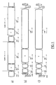
- curve a) represents the video signals of the HDMAC system of two consecutive lines (2i + 1) and 2 (i + 1), where i is a positive or zero integer.
- each video signal of curve a) there are three zones: a first DON area carrying a binary message coded in duobinary, the message consisting of a synchronization word (6 bits), followed by data and sound signals (99 bits), a CHR zone carrying the chrominance component, that is to say alternately the signal U in the odd lines and the signal V in the even lines, this signal being compressed in time, and - the LUM zone carrying the luminance component which is also temporally compressed, but less than the chrominance component, the entire video signal for 64 microseconds.
- Curve b) represents the extended video signals which are transmitted on a first channel A.
- a first SYNC zone carrying an analog synchronization signal necessary for the internal synchronization circuits of the magnetic tape recorder, followed by a continuous plateau for the clamping periods and a burst at 5.250 MHz which is intended for the slaving of a basic time corrector for reading
- - a DON + DON zone carrying the data of the line (2i + 1) followed by the data of the line 2 (i + 1), curve a
- - a LUM zone (2i + 1) carrying the luminance component of the line (2i + 1), curve a), but extended, since between each zone is provided a space for shaping the transitions.
- Curve c) represents the extended video signals which are transmitted on a second channel B.
- each signal of curve c) there are also four zones, of which the first two SYNC and DON + DON carry the same signals, with inversion of polarity, as at curve b), but of which the third CHR (2 + i) and LUM (2 + i) relate to the corresponding zones of curve a).
- the signal of curve a) is divided and extended in time to produce, on the one hand, the signal of curve b) transmitted on channel A and that of curve c) transmitted on channel B.
- each video line consists of 1316 samples, it is necessary to use for sampling a clock frequency of 10.5 MHz, which corresponds to a line duration of 125.333 microseconds.
- the useful line samples of the HDMAC signal are stored in memory at a clock frequency of 20.25 MHz.
- a 21 MHz clock is used for the data part and a 10.5 MHz clock for the chrominance and luminance parts.
- the blanking lines carrying the complement data at 20.25 MHz will be read entirely at the frequency of 10.5 MHz to reduce their spectrum to a value compatible with the bandwidth of the channel.
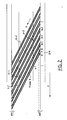
- the organization of the video frames of FIG. 2 is the recording format.
- the recording is done using the two channels A and B whose signals are recorded simultaneously on two different tracks, but adjacent, these two tracks forming what has been called a pair of tracks.
- the blanking intervals containing data at 20.25 MHz, are located alternately either at the end of the first quarter track or at the end of the third quarter track. Those of these intervals which are shown are indicated by k , k + 1, k + 2, etc.
- each image analysis frame is carried by a double track and a half.
- a magnetic strip BM whose direction of travel indicated by the arrow F is on the right to the left.
- the writing direction is indicated by the oblique arrow G rising from right to left.
- Double tracks are represented by pairs of oblique lines p, p + 1, p + 2, p + 3, etc. In each pair, the first oblique line, starting from the left, corresponds to the recording of the signals of channel A and the other line to the recording of the signals of channel B.
- the pair p records, starting from the zone k indicated in gray and located at the end of the first quarter, the beginning of a frame K; the pair (p + 1) records the end of the frame K up to the zone (k + 1) indicated in gray and located at the end of the third quarter, then the start of the frame (K + 1); the pair (p + 2) records the remainder of the frame (K + 1); the pair (p + 3) records the end of the frame (K + 1) up to the area (k + 2) indicated in gray and located at the end of the first quarter.
- the zones k, k + 1, k + 2, etc. obviously correspond to the frame suppression intervals which, in the HDMAC system, contain data complementary to 20.25 MHz. These zones are located alternately either at the end of the first quarter of a pair of tracks, or at the end of the third quarter, that is to say in regions where the head / tape contacts are better than on the edges of the BM band which improves the recording of additional data.
- the recording of a double track takes place during the 180 ° rotation of the head block, which means that the temporal processing of the information must deliver a useful signal of a duration slightly shorter than the writing of a double track.
- the switching of the heads, in reading can be carried out during the remaining time or "gap", without loss of information.
- the straight lines in dashed lines parallel to the edges of the strip BM, FIG. 2, determine between them and the adjacent edges the "gap" zones.
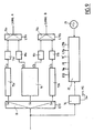
- Fig. 3 shows the means making it possible to place the zones k, k + 1, k + 2, etc., in the positions shown in FIG. 2.
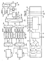
- a servo unit USM which has the role of keeping constant the tape running speed with respect to the capstan servo, not shown, and the rotation speed of the MT motor which drives the drum TT which carries the heads with regard to the servo heads.
- the speed and phase of the TT drum are regulated so that the signal written on the tracks corresponds exactly to the recording format, in particular as regards the position of the frame blanking intervals k , k + 1, etc., Fig. 2.
- the phase information of the TT head drum is given, at each turn, by the passage in front of a CT sensor, of an RT marker mounted on the periphery of the TT drum, producing a pulse.
- the USM unit comprises conventional CCT calculation circuits which are controlled by an MPS microprocessor and which have three inputs connected respectively to the sensor CT via a shaping circuit CMF, at the output of a generator.
- the electronic circuits CCT From the pulse transmitted by the sensor CT, the electronic circuits CCT generate, in relation to the pilot signal at the image frequency generated by the generator GSP, the control signal of the motor MT.
- the GSP generator operates from the incident video signal; in read mode, it operates from an oscillator stabilized by a quartz.
- the phase of the TT head drum is chosen so as to place the front edge of the frame synchronization 20 video lines after the switching point of the video heads, ie 2506 microseconds after this switching.
- the pulse produced by the passage of the reference frame RT in front of the sensor CT is also used as time information to control the video processing circuits and determine in the extended signal, the location of the area without information or "gap".
- the speed of rotation of the head drum TT is regulated on the basis of the speed of a tachometer disc Tc via a TCH sensor and CCT circuits.
- each HDMAC signal line has been described above to obtain the signals of curves b) and c) of FIG. 1, which are recorded on two separate channels A and B, according to the frame recording format shown in FIG. 2.
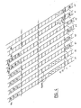
- the processing of the images with reference to the spatial diagram in FIG. 4 and the time diagrams of FIG. 5.
- the recording of a 625-line image requires three U-turns.
- the distribution of the extended video lines of a complete image over the pairs of tracks is as follows: - 4 times 104 extended lines + 2 times 105 extended lines, or 626 lines.
- An HDMAC image comprising only 625 lines, the 625 th extended line is, according to the invention, recorded twice, that is to say on the track of channel A and on the track of channel B, as shown in the Fig. 4, tracks s1 and s2.
- the duration of the "gaps" is modified accordingly. After a track of 104 lines, the duration of the "gap” is 2688 samples, or 256 microseconds while after a track of 105 lines, this duration is 2716 samples, or 258.6 microseconds.
- the first track p1 and the second track p2 carry, on time intervals 1 to 20, the lines of the end of the previous image and, on intervals 21 to 104, the first 168 lines of the current image , then tracks q1 and q2 carry lines 169 to 376 of the current image, then tracks r1 and r2, lines 377 to 584, and finally, tracks s1 and s2 carry, on intervals 1 to 20, the lines 585 to 625, plus line 625 repeated. From the intervals 21 of tracks s1 and s2, the following image is recorded.
- intervals 21 to 30 of the tracks p1 and p2 that is to say the range close to the first quarter, carry the lines of a weft suppression and that the intervals 72 to 81 of tracks q1 and q2, that is to say the range of the third quarter, carry the lines of the second weft suppression of the image.
- recording line 625 twice allows the same pattern to be repeated on the tape.
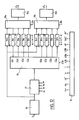
- the HDMAC video signal is transmitted to the input of an analog / digital converter 2, the eight-wire output of which is connected to a time expansion circuit 3 comprising two outputs which deliver extended video signals to two channels A and B, respectively.
- a sampling clock signal He is connected to the control input of converter 2.
- the frequency of the sampling clock He is 20.25 MHz, which corresponds to 1296 times the line frequency the HDMAC system video signal.
- the samples are coded on eight bits.
- Channels A and B are respectively connected to the inputs of two conventional recording circuits 4a and 4b, the outputs of which are connected to recording / reading switches 5a and 5b, the common contacts of which are respectively connected to a set of recording heads and reading 6a and 6b.
- Elements 4a, 4b, 5a, 5b, and 6a, 6b are, for example, part of an MG VCR of the consumer type, such as a VHS high fidelity VCR.
- switches 5a and 5b are shown in the recording state.
- switches 5a and 5b When the switches 5a and 5b are in the read state, they respectively connect the assemblies 6a and 6b to the inputs of two demodulators 7a and 7b whose signal outputs are respectively connected to the inputs of two analog digital converters 8a and 8b, and the control outputs to a time compression circuit 9.
- the outputs of the converters 8a and 8b are connected to the respective inputs of a time compression circuit 9, the three outputs of which are respectively connected to the corresponding inputs of a multiplexer 10, the output of which is connected to the input a digital / analog converter il which delivers an HDMAC video signal, which is available on output terminal 12.
- the set of heads 6a 6b comprises two pairs of heads, FIG. 7, the first pair Ka1, Ka2 being associated with channel A and the other pair Kb1, Kb2 with channel B.
- the four heads are carried by a drum T and are organized so that, in each pair, the heads are opposite at 180 °.
- the diametrical line joining the heads of the first pair and the one joining the heads of the second pair make an angle of 8.46 ° between them, which corresponds to five extended lines, i.e. a time difference of 5 x 125.333 microseconds.
- the width of each track recorded on the magnetic tape of the MG VCR is 25 micrometers, which is half the track width in the VHS system.
- the azimuth angle of the directions of the heads is chosen so as to ensure compatibility in reading with VHS cassettes.
- the two channels A and B are recorded simultaneously.
- a complete image is made up of six tracks, which corresponds to a revolution and a half of the drum T.
- Ka1, Kb1, Kb1 the doublet formed by Ka1, Kb1, then the doublet formed by Ka2, Kb2.
- the temporal processing of the video signal is planned to deliver to channels A and B an extended signal whose duration is slightly shorter than that which is the sweep time of a track.
- the time thus saved which has already been called "gap" above, is used to cover the switching of the heads.
- curve a) shows the working times of the head Ka1, curve b) the working times of the head Ka2, the diagram c) the detail of the essential times for channel A, the curve d) the times of work of head Kb1, curve e) working times of head Kb2 and curve f) essential times for channel B.
- Curves a) and b) show how the workings of heads Ka1 and Ka2 alternate.
- An image lasts 40 ms and two working times of the heads.
- diagram c) we have shown the positions, the durations of the gaps and the switching times of the heads Ka1 and Ka2.
- the first gap between two successive images that is to say after a track of 105 extended lines, has, as mentioned above, a duration of 258.6 microseconds and the instant of switching of the heads is at 77, 3 microseconds after the start of the gap.
- the second gap, after the first track with 104 extended lines, has a duration of 256 microseconds and the switching time of the heads is at 117.3 microseconds.
- the third gap after the second track with 104 extended lines, has a duration of 256 microseconds and the switching time of the heads is 160 microseconds after the start of the gap.
- This three-track motif repeats endlessly. For reasons of simplicity, in the spatial diagram of FIG. 4, shows the slight variations in the beginnings and ends of the gaps.
- curves d), e) and f) are offset, with a certain delay with respect to the curves a), b) and c). This is due to the 8.46 ° offset between the doublets, which has already been mentioned.
- Curve f) is analogous to curve c), but the time positions are indicated therein in numbers of samples, the sampling being done at 10.5 MHz.
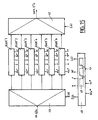
- the time expansion circuit 3, shown in FIG. 9, has its input connected, on the one hand, to the input of a demultiplexer 13 and, on the other hand, to that of a synchronization extractor 14.
- the signal Sw is used , in reading, of the initialization signal of the processing and corresponds to the start of the second frame of each image, that is to say to the line "1" on the channel B loaded in a data memory.
- the demultiplexer 13 has three outputs Sa, Sb and Sc, and a control input E13.
- the outputs Sa and Sb are respectively connected to two units 15a and 15b of temporal decompression of the zones CHR and LUM of the signal of FIG. 1.
- the output Sc is connected to the input of a digital data processing circuit 16.
- the respective outputs S′a and S′b of the units 15a and 15b are connected to the inputs of two digital / analog converters 17a and 17b .
- the processing circuit 16 has two outputs S ⁇ a and S ⁇ b which are respectively connected to two other digital / analog converters 18a and 18b.
- the outputs of the converters 17a and 18a are respectively connected to the inputs of a multiplexer 19a, the output of which is connected to channel A, FIG. 6.
- the outputs of the converters 17b and 18b are respectively connected to the inputs of a multiplexer 19b, the output of which is connected to channel B, FIG. 6.
- L19a and L19b have been noted the control inputs of the multiplexers 19a and 19b.
- An output of the synchronization extractor circuit 14 is connected to the input of a main time base 20, the clock input of which is connected to the output of a stabilized oscillator 21.
- the main time base 20 delivers signals He, Hl and Hl ′, as well as logic control signals E13, L19a and L19b to the corresponding circuits shown in FIG. 9.
- Another output of the synchronization extractor circuit 14 is connected to a corresponding input, not shown, of the video recorder MG in order to apply to it a synchronization signal Sw. The corresponding connection is also shown in FIG. 6.
- the signal Sw is a synchronization signal which corresponds to the start of each complete writing sequence on the two channels A and B. This sequence, as will be better understood below, at a duration of ?? frames of the incident HDMAC signal, at the end of which a new cycle begins again.
- the signal Sw in the form of a bit, is produced by decoding, in line 625 of the signal HDMAC of the word LSW, and the selection of the word W1 or W2.
- the signal Sw is intended to be recorded on a particular track of the magnetic tape of the video tape recorder MG, ie the track "control-track", with the normal signal of piloting of the servo-mechanisms regulating the speed of progression Of the band.
- the recording of the signal Sw on the "control-track” can be carried out using a system such as that described in the document FR-A-2 458 874.
- the signal E13 is a two-bit word which, applied to the control input of the demultiplexer i3, causes: - during 216 clock periods He at 20.25 MHz, the routing of the digital signal delivered by the analog / digital converter 2, by the output Sc, to the processing circuit 16 which thus receives the samples corresponding to the DON area of each video signal shown in curve a) of FIG. 1, - then, during the following 1080 clock periods, guiding the digital signal alternately to unit 15a or unit 15b, two consecutive lines out of four.
- the signal L19a controls the multiplexer 19a so that, for 37 clock periods Hl ′, it lets the analog signal coming from the converter 17a pass to channel A, then, for 217 clock periods Hl ′, the analog signal delivered by the converter 18a, then until the end of the line, the signal delivered by the converter 17a.
- the signal L19b likewise controls the multiplexer 19b.
- the decompression unit 15a comprises a demultiplexer 22 with six outputs whose input is connected to the output Sa of the demultiplexer 13 and whose outputs are respectively connected to the inputs of six random access memories RAM1 to RAM6.
- the outputs of the memories RAM1 to RAM6 are respectively connected to six inputs of a multiplexer with seven inputs 23, the seventh input of which is connected to the output of a synthesis circuit of synchronization signal and frequency burst 24 and whose output is connected to digital / analog converter 17a.
- the unit 15a is completed by an annex time base 25.
- the structure of the unit 15b is identical to that of the unit 15a.
- the annex time base 25 delivers the following control or clock signals: the signal E22 used to select, in the demultiplexer 22, the output to which the chrominance and luminance components received from the demultiplexer 13 are to be transmitted in order to record them in one of the memories RAM1 to RAM6, the write clock He for the memories RAM1 to RAM6, ie here a clock signal at 20.25 MHz, the recording control signal w used to select and switch one of the memories RAM1 to RAM6 in write mode, the addressing signal ad in the memories RAM1 to RAM6, the read control signal r used to select and switch in reading mode one of the memories RAM1 to RAM6 or the synthesis circuit 24, the reading clock H1 of the memories RAM1 to RAM6, that is to say here at 10.5 MHz, and - the control signal L23 used to select, at each line read, the input connected to circuit 24, then the input connected to memory RAM1 to RAM6 to be read.
- the signal E22 used to select, in the demultiplexer 22, the output to which the chrominance and
- the frequency of the reading clock H1 being of the order of half that of the writing clock He, the areas CHR and LUM are found, after reading, to be extended with a length almost twice as long.
- the frequency of the clock Hl is slightly greater than half that of the clock He to allow the SYNC part extracted from the circuit 24 to be housed and to provide the space necessary for constituting the gap.
- the operation of the unit 15a, FIG. 10, will now be described with reference to curves b) and c) of FIG. 1.
- Each of these curves is broken down into three parts: a first SYNC part, a second DON + DON and a third CHR + LUM.
- the SYNC part includes a negative synchronization pulse followed by a reference frequency burst.
- the negative pulse is intended to be recognized in the MG video recorder which uses it for its own operation in a conventional manner.
- the frequency of the reference burst is equal to 336 times the line frequency and is intended to be used in the reading chain.
- the content of this SYNC part is extracted, in recording mode, from circuit 24 at the start of each line extended at the rate of the clock H1.
- the content of the second part DON + DON will be described below.
- the content of the third part CHR + LUM is extracted from one of the memories RAM1 to RAM6, selected by the time base 25 and also at the rate of the clock Hl. It also appears that the selection of the inputs in the multiplexer 23 is controlled as a function of the time position of the parts in the extended line and of a program which is recorded in the time base 25 and which results, for the skilled person. , from the examination of the diagrams of FIG. 11.
- diagram i shows the incident HDMAC signal at the end of one image and at the start of the next.
- Diagram m) shows that the memory RAM4 of circuit 15a receives the areas CHR and LUM of line 1. The content 1 ′ of this memory is read later with a clock almost twice slower to be inserted in channel B, diagram p).
- This RAM4 memory of 15a becomes available again to memorize the content of line 13 and this content is read later.
- Diagram e) shows that the memory RAM3 receives the areas CHR and LUM of line 2 whose content 2 ′ is read later. Arrows have been drawn to illustrate the transfers of the contents of the successive lines. The different reads and writes are controlled by the time bases 20 and 25 through the signals E13, E22 and L23. Examination of the other diagrams makes it possible to immediately understand the operation of the units 15a and 15b, which make it possible to insert the extended parts of CHR and LUM into channels A and B.
- line 625 is stored in memory RAM3 of circuit 15a, diagram f) and in memory RAM3 of circuit 15b, diagram l). These memories will not be re-read; they only contain digital data, which is processed by circuit 16.
- Fig. 11 also showing the gaps necessary for the recording system with two heads for each channel also makes it possible, by considering the delays between writing and reading, to understand the usefulness of the six memories per unit.
- the values of the gap durations are given in Figs. 5 and 8.
- the data processing circuit 16 is shown in detail in FIG. 12. It includes a Viterbi decoder 26 whose input is connected to the output Sc of the demultiplexer 13 and whose output is first connected to the input of a random access memory 27 whose output is connected to the input of a demultiplexer 28 with twice four outputs S ⁇ a1, S ⁇ a2, S ⁇ a3, S ⁇ a4 and S ⁇ b1, S ⁇ b2, S ⁇ b3, S ⁇ b4 which are respectively connected to the inputs of twice four random access memories 29a, 30a, 31a, 32a and 29b, 30b, 31b, 32b.
- the outputs of memories 29a, 30a, 31a and 32a are respectively connected to the four inputs of a multiplexer 33a with five inputs, the fifth input of which is connected to the output of a memory 34a, the input of which is connected to the output of the decoder from Viterbi 26.
- the output of the multiplexer 33a is connected to the input of an NRZ / duobinary encoder 35a.
- the outputs of memories 29b, 30b, 31b and 32b are respectively connected to the four inputs of a multiplexer 33b with five inputs, the fifth input of which is also connected to the output of a memory 34b, the input of which is connected to the output of the Viterbi decoder.
- the output of the multiplexer 33b is connected to the input of an NRZ / duobinary encoder 35b.
- the outputs of encoders 35a and 35b are respectively connected to outputs S ⁇ a and S ⁇ b, Fig. 9.
- the processing circuit 16 is completed by an annex time base 36.
- the annex 36 time base delivers the following control and clock signals: the signal Str which, during the duration of line 625, inhibits the entry of memory 27 and activates the inputs of memories 34a and 34b, the write / read clock signal He for memory 27, and for writing to memories 29a, 30a, 31a, 32a, 29b, 30b, 31b and 32b, and 34a and 34b, the reading clock Hl ⁇ of the memory 27 and of the memories 29a, 30a, 31a, 32a and 29b, 30b, and 31b, 32b, - the reading clock Hl ⁇ of memories 34a and 34b, the recording control signal w used to select and switch into writing mode one of the memories 29a to 32b, and 34a and 34b, the read control signal r used to select and switch one of the memories 29a to 32b, and 34a and 34b in reading mode, the signal E28 used to select, in the demultiplexer 28, the output to which the data read from the memory 27 are to be transmitted in order to write them in one of the
- the Viterbi decoder 26 receives from the demultiplexer 13, FIG. 9, the digital signal from the DON area, curve a) of FIG. 1, in which the data is coded in duobinary and delivers these same data in NRZ code, using the Viterbi algorithm which checks the criterion of "maximum likelihood a posteriori", that is to say the search for the most probable path between two states successive of the system.
- the duobinary code is a partial response code which introduces a certain correlation in the transmitted signal. In particular, duobinary coding prohibits certain transitions.
- the latter Whenever a prohibited transition is detected on reception in the decoder, the latter resets the decoding processing and, moreover, delivers an error signal.
- the error signal In the decoder 26, the error signal is not used; on the other hand, it will be seen that, in the Viterbi decoders used in the reading chain, the error signals are counted and used to make decisions.
- the random access memory or RAM 27 has a capacity of 512 bits.
- a line of the incident video signal for example the line "3”
- the memory 27 is put into write mode for 216 write clock periods He , after which the decoder 26 no longer receives signals.
- the time base 36 then advances the addresses by four additional steps. This offset of the address has the effect of adding four bits to zero in the memory 27.
- Each DON + DON set is selectively transferred, during the time corresponding to the CHR + LUM area, by the demultiplexer 28, either in the pair of memories 29a and 29b, or in the pair of memories 30a and 30b, or in the pair of memories 31a and 31b, or in the pair of memories 32a and 32b.
- the selection is made by signal E28.
- the memory 27 is reset to zero by the reset signal of the time base 36.
- the reading clock Hl ′ of the pairs of memories 29a, 29b; 30a, 30b; 31a, 31b; and 32a, 32b is slower than the write clock He. This was 20.25 MHz while the reading clock Hl ′ is 21 MHz.
- the spectrum of the duobinary signal which will be reconstituted after conversion in the coders 35a or 35b, will therefore be increased from 5.06 MHz to 5.25. This slight increase in the frequency congestion of data encoded in duobinary remains compatible with a channel whose bandwidth is of the order of 6 MHz.
- the memories 34a and 34b are provided for storing, both, the data carried by the line 625.
- the write clock He of these memories is the same as that of the memories 29a to 32b, and their read clock Hl ′ operates at 21 MHz.
- the two memories 34a and 34b have a capacity of 2048 bits greater than the capacity of memories 29a to 32b which is only 512 bits.
- the reading of line 625 to channels A and B occupies a time less than the duration of a current extended line, ie 125.3 microseconds.
- the remaining space can optionally be used for the insertion, by the circuits 15a and 15b, of test or adjustment signals, for example, for checking the correction of the evaluation of the read heads, depending on the variations. tape tension.
- curve a) shows the incident HDMAC video signal and curve b) shows how the content of memory 27 evolves. This content being that of an odd line DON data packet (2i + 1), to which, at the following line is added that of a pair line 2 (i + 1) and, finally, being reset to zero upon transfer to one of the pairs of memories 29a, 29b or 30a, 30b, and so on.
- diagrams k) and l) show the contents of channels A and 8, with regard to the data.
- the signals L33a and L33b of the annexed time base 36 are used to respectively route the contents of the memories 29a, 29b; 30a, 30b; ...; 32a, 32b and 34a, 34b to the encoders 33a and 33b according to a program which corresponds to the diagrams in FIG. 13 and which is recorded in the time base 36.
- the converters 17a and 18a, FIG. 6, transform the signals coming from the outputs S ⁇ a and S ⁇ a in analog signals and the multiplexer 19a performs the nesting of the DON + DON part delivered by the converter 18a between the SYNC and CHR + LUM parts delivered by the converter 17a.
- the multiplexer 19a therefore delivers the content of channel A which is formed of a series of extended lines conforming to the signals of either curve b) or curve c).
- the process is the same.
- the demodulators 7a and 7b, FIG. 14, are part of the MG VCR where they fulfill conventional functions, namely the amplification and correction of the signals read by the heads Ka1, Ka2 and Kb1, Kb2, then the demodulation, filtering and de-emphasis of these signals. As shown in Fig. 14, they each comprise an actual demodulator 37a or 37b, a synchronization separator circuit 38a or 38b, and a conventional drop-out detector 39a or 39b. The inputs of 37a and 39a, and of 37b and 39b are respectively connected in parallel to channel A and to channel B. A conventional output of each demodulator 37a or 37b is connected to the input of the corresponding separator 38a or 38b.
- the synchronization separator circuits detect the negative pulses of the SYNC parts of the extended lines read and orient them respectively, with the reference bursts which follow them, towards their outputs SVa and SVb.
- the drop-out detectors 39a and 39b respectively deliver on their outputs DOa and DOb a bit "1" or a bit "0" depending on whether the extended line being read is affected by a sudden and lasting drop in amplitude, for example exceeding a few microseconds, of the signal read.
- the signal outputs of demodulators 37a and 37b are respectively connected to the inputs of the associated analog / digital converters 8a and 8b.
- Each analog / digital converter 8a or 8b converts the analog signal applied to samples coded on eight bits; it operates successively with different sampling clocks, i.e. 672 times the line frequency for the SYNC and CHR + LUM parts, Fig. 1, or 1344 times the extended line frequency for the DON + DON part.
- sampling clocks i.e. 672 times the line frequency for the SYNC and CHR + LUM parts, Fig. 1, or 1344 times the extended line frequency for the DON + DON part.
- the clock input is connected to the output of a switch Xa or Xb which receives the two sampling clocks associated with channel A or B.
- These clocks are synthesized from the burst of reference added in the SYNC part during the recording.
- the value of the frequency of the reference burst is 336 times the line frequency and is therefore theoretically in a simple ratio either 1/2 with Hl, or 1/4 with Hl ′.
- there are two pairs of sampling clocks Hla *, Hl′a * and Hlb *, Hl′b * which are synthesized separately from the bursts delivered to the SVa and SVb outputs, respectively.
- the time compression circuit 9, shown in FIG. 14, has two signal inputs Ea and Eb respectively connected to the outputs of the converters 8a and 8b and two pairs of control inputs respectively connected to the outputs DOa, DOb and SVa, SVb.
- the input Ea is connected to the input of a demultiplexer 40a with two outputs, one of which is connected to a time compression unit 41a of the parts CHR + LUM of the extended lines read.
- the input Eb is connected to a demultiplexer 40b with two outputs, one of which is connected to the input of a time compression unit 41b of the CHR + LUM parts of the extended lines read.
- the second outputs of the demultiplexers 40a and 40b are respectively connected to two inputs E′a and E′b of a processing circuit 42 for the digital data DON + DON of the extended lines read.
- the outputs of the units 41a and 41b, and of the processing circuit 42 are respectively connected to the inputs E ⁇ a, E ⁇ b and E ⁇ c of the multiplexer 10 with three inputs whose output is connected to the converter 11, FIG. 6.
- the signals delivered by the outputs DOa, DOb, SVa and SVa are applied to corresponding inputs of a main time base 43.
- This comprises two memories Qa and Qb whose inputs respectively receive the signals of DOa and DOb, and two burst separators SEPa and SEPb which receive SVa and SVb signals respectively.
- the outputs of the memories Qa and Qb are connected to two corresponding outputs qa and qb of the time base 43.
- the output of the separator SEPa is connected to two frequency multipliers MULa and MUL′a whose outputs deliver the reconstituted clocks Hla * and Hl′a *.
- the output of the SEPb separator is connected to two multipliers which supply the reconstituted clocks Hlb * and Hl′b *.
- the time base 43 also comprises a stabilized oscillator 44 supplying a read clock He *, which is equal to the clock He used in the recording chain, and a logic circuit 45 which supplies switching signals E37a, E37b and L10 to the various circuits concerned.
- the main time base 43 also has an input to which a signal Sw * emitted by the video recorder MG is applied on reading the bit Sw on the "control-track” track.
- the signal Sw * makes it possible, in read mode, to initialize, in the time base 43, the processing process in the two channels A and B, the instant "zero” corresponding to the beginning of the line "1", on channel B, after a gap and a line "625".
- the clock inputs of the converters 8a and 8b are connected to the outputs of switches Xa and Xb, which receive the corresponding sampling clocks.
- the frequency multipliers of the time base 43 are, for example, well-known phase-locked loop oscillators.
- the logic circuit 45 represented symbolically includes counters capable, for each channel A or B, from the detection of the negative synchronization pulse and synthesized clocks to form the signals E40a, E40b which respectively control the simultaneous operation of the switch Xa and the demultiplexer 40a, or the simultaneous operation of the switch Xb and the demultiplexer 40b.
- the compression unit 41a comprises a demultiplexer 46 with six outputs whose input is connected to the first output of the demultiplexer 40a and whose outputs are respectively connected to the inputs of six random access memories RAM′1 to RAM′6.
- the outputs of the memories RAM′1 to RAM′6 are respectively connected to the six inputs of a multiplexer 47 whose output is connected to the input E ⁇ a of the multiplexer 10, FIG. 14.
- Unit 41a is completed by an additional time base 48.
- the structure of unit 41b is identical to that of unit 41a.
- the annex 48 time base delivers the following control or clock signals: the signal E46 used to select, in the demultiplexer 46, the output to which the CHR + LUM part is to be transmitted for writing to one of the memories RAM′1 to RAM′6, the write clock Hla * in the memories RAM′1 to RAM′6, the clock Hla * being received from the main time base 43, the write control signal w used to select and switch one of the memories RAM′1 to RAM′6 in write mode, - the addressing signal ad in the memories RAM′1 to RAM′6, the read control signal r used to select and switch one of the memories RAM′1 to RAM′6 in reading mode, the read clock He * of the memories RAM′1 to RAM′6, the clock He * being received from the main time base 43, and - The control signal L47 used to select, for each reconstructed line, the input connected to the memory RAM′1 to RAM′6 which is to be read.
- the annexed time base 48 receives from the main time base 43 the signal qa which is at "1" when the part CHR + LUM being written in one of the memories RAM′1 to RAM′6 is assigned of a drop-out.
- the time base 48 comprises, on the one hand, a counter 49 which contains the position of the samples in each line and, on the other hand, a line counter 50. It is supplemented by a logic circuit 48, which depending on the count in 49 delivers the signal E46 and, depending on the count in 50 and the qa information, delivers the signal L47.
- the small hatched rectangles represent the same information compressed when they are read in order to be multiplexed with the information coming from the unit 41b in order to reconstruct the analog zones of the reconstructed HDMAC signal, diagram g).
- the content of the extended line 593 is affected by a drop-out, it is written in the memory RAM′4, but at the time of its instant of reading the signal L47 will direct the multiplexer 47 towards the memory RAM′2 so that the old extended line 589 will be read and will take the place of the extended line 593.
- the extended line 625 appears, both in channel A and in channel B. It has been arbitrarily chosen to read the corresponding compressed line in the memory RAM′2 of the compression unit 41a. However, in the event of a drop-out signaled by qa , the RAM′2 memory of the 4lb compression unit will be read.
- the digital data processing circuit 42 comprises two duobinary Viterbi decoders 52a and 52b, the inputs of which are respectively connected to the inputs E′a and E′b and the signal outputs of which are respectively connected to the inputs of two demultiplexers 53a and 53b.
- Each multiplexer 53a or 53b with four outputs which are respectively connected to the inputs of four random access memories RAMa1 to RAMa4 or RAMb1 to RAMb4.
- Each of these memories has a capacity of 512 bits, that is to say that it is capable of memorizing a burst of data DON + DON, curve b) and c), FIG. 2.
- the outputs of memories RAMa1 to RAMa4 are respectively connected to the inputs of a multiplexer 54a while the outputs memories RAMb1 to RAMb4 are respectively connected to the inputs of a multiplexer 54b.
- the outputs of the multiplexers 54a and 54b are respectively connected to the inputs of a multiplexer 55 whose output is connected to the input of a buffer memory 56, whose capacity is also 512 bits.
- the output of the buffer memory 56 is connected to an input of a multiplexer 57, the second input of which is connected to the output of a multiplexer 66.
- the two inputs of the multiplexer 56 are respectively connected to the outputs of two memories RAMb5 and RAMa5.
- the inputs of the memories RAMb5 and RAMa5 are respectively connected to the inputs E′b and E′a.
- the output of the multiplexer 57 is connected to the input of a duobinary coder 58 whose output is connected to the multiplexer 10, FIG. 14.
- Each Viterbi 52a or 52b duobinary decoder also has an output Va or Vb, respectively, which delivers a "1" bit each time an erroneous configuration has been encountered during decoding.
- the outputs Va and Vb are respectively connected, inside an annex time base 59, to the inputs of two counters 60a and 60b.
- the counter 60a counts the number of bits "1" delivered by the output Va and stores this number in an associated memory 61a whose capacity is equal to two words.
- the counter 60b also works in relation to a memory 61b.
- the outputs of memories 61a and 61b are connected to the two inputs of a comparator 62, the output of which is connected to an input of a memory selection circuit 63.
- the memory selection circuit 63 still has two inputs which receive the information qa and qb of logic circuit 43, Fig. 14.
- the output of the memory circuit 63 is connected to a logic circuit 64 comprising, inter alia, a sample counter and a row counter, not shown.
- the clock input of the memory 56 is connected to the output of a switch 65 which receives the two clocks Hl′a * and Hl′b * and which is controlled in the same way as the multiplexer 55.
- the time base 59 delivers the following control or clock signals: - the signals E53a and E53b used to select, in the demultiplexers 53a and 53b, the respective outputs to which the data bursts DON + DON are at transmit to save them in the memories RAMa1 to RAMa4, for those which come from channel A, and RAMb1 to RAMb4, for those which come from channel B, - the write and read clock Hl′a * in the memories RAMa1 to RAMa4, - the write and read clock Hl′b * in the memories RAMb1 to RAMb4, - the write clock Hl ⁇ a * in the memory RAMa5 and the write clock Hl "b * in the memory RAMb5, the recording control signal w used to select and switch into write mode one of the memories RAMa1 to RAMb4 or the memory 56, the addressing signal ad in the memories RAMa1 to RAMb4 and the memory 56, the read command signal r used to select and switch one of the memories RAMa1 to RAMb4 or the memory 56 in
- Diagrams a) and m) show the bursts respectively read in channels A and B.
- the extended line “588" of channel A carries the data of the incident lines “587” and “588” and the line scope "587” of channel B carries the same data.
- the data of the extended line “588” are shown routed to the memory RAMa1, curve b), by the multiplexer 53a while the data of the extended line "587” are routed by the demultiplexer 50b to the memory RAMb1, curve 1) .
- the two bursts of data were, by example, considered as error free by the decoders of 52a and 52b.
- the corresponding content of the memory associated with the other channel is selected to fill the memory 56.
- the comparator 62 delivers the information indicating the extended line whose data contains the least number of errors, and the logic circuit 63, as a function of this information plus the drop-out information qa and qb , chooses, to fill memory 56, the memories RAMa1 to RAMb4 to be read as well as in these memories which part, first or second, must be read.
- the a priori selection of the memory to be read back is the memory RAMa5 corresponding to channel A.
- the content of the memory RAMb5 is read.
- the additional data carried by the lines of the frame blanking interval they undergo identical processing to the CHR + LUM components of the current lines, except for line 625.
- the time base 43 inhibits the transmission of information qa and qb to the time bases 48 and 59.
- the additional data d is not replaced 'a line by those of another.
- circuit diagrams comprising separate well-differentiated members, such as memories, demultiplexers, multiplexers, etc. It is obvious that one could achieve the same functions using one or more microprocessors with associated memories.
Landscapes
- Engineering & Computer Science (AREA)
- Multimedia (AREA)
- Signal Processing (AREA)
- Television Signal Processing For Recording (AREA)
- Signal Processing For Digital Recording And Reproducing (AREA)
Applications Claiming Priority (2)
| Application Number | Priority Date | Filing Date | Title |
|---|---|---|---|
| FR8912220 | 1989-09-13 | ||
| FR8912220A FR2651949B1 (fr) | 1989-09-13 | 1989-09-13 | Procede d'enregistrement et de lecture de signaux de television a haute definition. |
Publications (1)
| Publication Number | Publication Date |
|---|---|
| EP0418180A1 true EP0418180A1 (de) | 1991-03-20 |
Family
ID=9385611
Family Applications (1)
| Application Number | Title | Priority Date | Filing Date |
|---|---|---|---|
| EP90460032A Ceased EP0418180A1 (de) | 1989-09-13 | 1990-09-07 | Verfahren zum Aufzeichnen und Wiedergeben von Fernsehsignalen mit hoher Auflösung |
Country Status (2)
| Country | Link |
|---|---|
| EP (1) | EP0418180A1 (de) |
| FR (1) | FR2651949B1 (de) |
Cited By (1)
| Publication number | Priority date | Publication date | Assignee | Title |
|---|---|---|---|---|
| EP0540348A3 (en) * | 1991-10-31 | 1993-09-22 | Sharp Kabushiki Kaisha | Apparatus and method of recording and reproducing a colour video signal |
Citations (4)
| Publication number | Priority date | Publication date | Assignee | Title |
|---|---|---|---|---|
| EP0190919A2 (de) * | 1985-02-05 | 1986-08-13 | Sony Corporation | Aufzeichnungssystem |
| EP0243739A2 (de) * | 1986-04-24 | 1987-11-04 | GRUNDIG E.M.V. Elektro-Mechanische Versuchsanstalt Max Grundig holländ. Stiftung & Co. KG. | Verfahren zur Aufbereitung von Fernsehsignalen |
| EP0260045A2 (de) * | 1986-09-01 | 1988-03-16 | Matsushita Electric Industrial Co., Ltd. | Verfahren zum Aufzeichnen eines Videosignals und das assoziierende Aufzeichnungs-/Wiedergabegerät |
| EP0262362A2 (de) * | 1986-08-30 | 1988-04-06 | GRUNDIG E.M.V. Elektro-Mechanische Versuchsanstalt Max Grundig holländ. Stiftung & Co. KG. | Verfahren zur Aufzeichnung und Wiedergabe des in einem Fernsehsignal übertragenen Datenpakets |
-
1989
- 1989-09-13 FR FR8912220A patent/FR2651949B1/fr not_active Expired - Lifetime
-
1990
- 1990-09-07 EP EP90460032A patent/EP0418180A1/de not_active Ceased
Patent Citations (4)
| Publication number | Priority date | Publication date | Assignee | Title |
|---|---|---|---|---|
| EP0190919A2 (de) * | 1985-02-05 | 1986-08-13 | Sony Corporation | Aufzeichnungssystem |
| EP0243739A2 (de) * | 1986-04-24 | 1987-11-04 | GRUNDIG E.M.V. Elektro-Mechanische Versuchsanstalt Max Grundig holländ. Stiftung & Co. KG. | Verfahren zur Aufbereitung von Fernsehsignalen |
| EP0262362A2 (de) * | 1986-08-30 | 1988-04-06 | GRUNDIG E.M.V. Elektro-Mechanische Versuchsanstalt Max Grundig holländ. Stiftung & Co. KG. | Verfahren zur Aufzeichnung und Wiedergabe des in einem Fernsehsignal übertragenen Datenpakets |
| EP0260045A2 (de) * | 1986-09-01 | 1988-03-16 | Matsushita Electric Industrial Co., Ltd. | Verfahren zum Aufzeichnen eines Videosignals und das assoziierende Aufzeichnungs-/Wiedergabegerät |
Non-Patent Citations (2)
| Title |
|---|
| IEEE TRANSACTIONS ON CONSUMER ELECTRONICS, vol. 34, no. 1, février 1988, pages 78-83, IEEE, New York, US; M. ITOGA et al.: "Two channel FM recording for high-definition baseband signals" * |
| LE HAUT-PARLEUR, no. 1753, juin 1988, pages 78-82; E. GÜTTNER: "Magnetoscope a large bande pour signaux D2-MAC/Paquet" * |
Cited By (2)
| Publication number | Priority date | Publication date | Assignee | Title |
|---|---|---|---|---|
| EP0540348A3 (en) * | 1991-10-31 | 1993-09-22 | Sharp Kabushiki Kaisha | Apparatus and method of recording and reproducing a colour video signal |
| US5477336A (en) * | 1991-10-31 | 1995-12-19 | Sharp Kabushiki Kaisha | Apparatus and method of recording and reproducing video signal |
Also Published As
| Publication number | Publication date |
|---|---|
| FR2651949A1 (fr) | 1991-03-15 |
| FR2651949B1 (fr) | 1991-10-25 |
Similar Documents
| Publication | Publication Date | Title |
|---|---|---|
| FR2562362A1 (fr) | Systemes de traitement ou de visualisation video | |
| FR2552606A1 (fr) | Signal de television de haute definition pour systeme de conversion des standards film-television | |
| FR2480542A1 (fr) | Appareil d'enregistrement et/ou de reproduction de signaux numeriques video et audio | |
| FR2466925A1 (fr) | Magnetoscope a bande a balayage helicoidal | |
| FR2468266A1 (fr) | Procede et dispositif de correction d'erreur dans un signal numerique | |
| FR2606576A1 (fr) | Dispositif pour transmettre des images de television haute definition dans des canaux a bande etroite | |
| FR2475341A1 (fr) | Procede et appareil de dephasage a action rapide, destines a etre utilises dans des systemes d'echantillonnage numerique | |
| FR2475339A1 (fr) | Appareil et procede d'enregistrement et de reproduction numerique | |
| FR2481038A1 (fr) | Appareil d'enregistrement et de reproduction de donnees video sous forme numerique | |
| CH638355A5 (fr) | Procede et appareil de traitement de signaux d'images en couleurs. | |
| CH638359A5 (fr) | Procede et dispositif de traitement d'un signal video en couleur. | |
| FR2543387A1 (de) | ||
| WO1997005702A1 (fr) | Entrelacement/desentrelacement d'elements de donnees | |
| FR2664456A1 (fr) | Circuit de lecture de signaux numeriques d'images. | |
| EP0011016B1 (de) | Übertragungssystem für audio-visuelle Fernsehsignale, die mittels einer Pilotfrequenz synchronisiert sind, und Anwendungsverfahren | |
| EP0418180A1 (de) | Verfahren zum Aufzeichnen und Wiedergeben von Fernsehsignalen mit hoher Auflösung | |
| EP0365090B1 (de) | Einrichtung zum Verdoppeln der Rate von Fernsehbild-Signalen, und Fernsehbild-Dekodierer mit einer solchen Einrichtung | |
| EP0360719A1 (de) | Verfahren zum Aufzeichnen auf einem magnetischen Band und Wiedergabe von D2-MAC/Paket-Signalen und entsprechende Vorrichtungen | |
| FR2594283A1 (fr) | Procede numerique d'enregistrement et de reproduction de signaux de television | |
| EP0071510A1 (de) | Verfahren und Einrichtung zur Wiederherstellung eines Fernsehbildes aus einem Halbbild eines digitalen Gesamtsignals | |
| EP0242923B1 (de) | Videosignalumwandler | |
| FR2536933A1 (fr) | Systeme multiplex d'enregistrement et systeme multiplex d'enregistrement et de restitution pour enregistrement sur bande video | |
| EP0428216B1 (de) | Gerät zur verbesserten Dekodierung von HD-MAC-Fernsehsignalen | |
| FR2575352A1 (fr) | Systeme de transmission de television en couleur ou de couleur d'information a codage en multiplexage dans le temps et emetteur et recepteur d'information convenant a cet effet | |
| EP0380181A1 (de) | Aussendungsstufe für ein in Auflösung erweitertes Fernsehbildübertragungssystem, Übertragungssystem, das eine solche Stufe umfasst und Empfangsstufe für ein solches System |
Legal Events
| Date | Code | Title | Description |
|---|---|---|---|
| PUAI | Public reference made under article 153(3) epc to a published international application that has entered the european phase |
Free format text: ORIGINAL CODE: 0009012 |
|
| AK | Designated contracting states |
Kind code of ref document: A1 Designated state(s): DE ES GB IT NL |
|
| 17P | Request for examination filed |
Effective date: 19910905 |
|
| 17Q | First examination report despatched |
Effective date: 19931027 |
|
| STAA | Information on the status of an ep patent application or granted ep patent |
Free format text: STATUS: THE APPLICATION HAS BEEN REFUSED |
|
| 18R | Application refused |
Effective date: 19950422 |