EP0418211A2 - Système de mesure incrémental - Google Patents
Système de mesure incrémental Download PDFInfo
- Publication number
- EP0418211A2 EP0418211A2 EP90890239A EP90890239A EP0418211A2 EP 0418211 A2 EP0418211 A2 EP 0418211A2 EP 90890239 A EP90890239 A EP 90890239A EP 90890239 A EP90890239 A EP 90890239A EP 0418211 A2 EP0418211 A2 EP 0418211A2
- Authority
- EP
- European Patent Office
- Prior art keywords
- scale
- scanning
- reflector
- scale body
- light source
- Prior art date
- Legal status (The legal status is an assumption and is not a legal conclusion. Google has not performed a legal analysis and makes no representation as to the accuracy of the status listed.)
- Granted
Links
Images

Classifications
-
- G—PHYSICS
- G01—MEASURING; TESTING
- G01D—MEASURING NOT SPECIALLY ADAPTED FOR A SPECIFIC VARIABLE; ARRANGEMENTS FOR MEASURING TWO OR MORE VARIABLES NOT COVERED IN A SINGLE OTHER SUBCLASS; TARIFF METERING APPARATUS; MEASURING OR TESTING NOT OTHERWISE PROVIDED FOR
- G01D5/00—Mechanical means for transferring the output of a sensing member; Means for converting the output of a sensing member to another variable where the form or nature of the sensing member does not constrain the means for converting; Transducers not specially adapted for a specific variable
- G01D5/26—Mechanical means for transferring the output of a sensing member; Means for converting the output of a sensing member to another variable where the form or nature of the sensing member does not constrain the means for converting; Transducers not specially adapted for a specific variable characterised by optical transfer means, i.e. using infrared, visible, or ultraviolet light
- G01D5/32—Mechanical means for transferring the output of a sensing member; Means for converting the output of a sensing member to another variable where the form or nature of the sensing member does not constrain the means for converting; Transducers not specially adapted for a specific variable characterised by optical transfer means, i.e. using infrared, visible, or ultraviolet light with attenuation or whole or partial obturation of beams of light
- G01D5/34—Mechanical means for transferring the output of a sensing member; Means for converting the output of a sensing member to another variable where the form or nature of the sensing member does not constrain the means for converting; Transducers not specially adapted for a specific variable characterised by optical transfer means, i.e. using infrared, visible, or ultraviolet light with attenuation or whole or partial obturation of beams of light the beams of light being detected by photocells
- G01D5/347—Mechanical means for transferring the output of a sensing member; Means for converting the output of a sensing member to another variable where the form or nature of the sensing member does not constrain the means for converting; Transducers not specially adapted for a specific variable characterised by optical transfer means, i.e. using infrared, visible, or ultraviolet light with attenuation or whole or partial obturation of beams of light the beams of light being detected by photocells using displacement encoding scales
- G01D5/34707—Scales; Discs, e.g. fixation, fabrication, compensation
- G01D5/34715—Scale reading or illumination devices
Definitions
- the invention relates to an incremental measuring system according to the preamble of claim 1.
- the invention further relates to a method according to the preamble of claim 7 for comparing the photoelectric receivers in an incremental measuring system.
- Corresponding measuring systems can also be built as resolvers when using a circular scale and a correspondingly circular protective housing.
- the measuring graduation of the scale is scanned via the scanning grating using the transmitted light method.
- the use of a single light source has the advantage of a low power requirement and a reasonably uniform illumination of the measuring field, but the projection path to be followed by the light source results in a considerable space requirement up to the condenser and thus a large light range of the tubular protective and carrier housing.
- it is known to supply the light via optical fibers this makes the overall arrangement complex and considerable light losses occur.
- the scanning unit on the ceiling of the protective housing which supports the scale tape in the middle
- the arrangement is only possible with a scale tape with reflective measuring graduation arranged horizontally on the ceiling of the pipe housing.
- phase error occurs as a further error, which means that the phase spacings of the signals generated on the receivers by the scanning grids offset by fractional divisions do not correspond to the nominal values of usually 90 or 180 °, but instead deviate from these nominal values .
- Subordinate compensation circuits are also used for the adjustment of this phase error, which are complex and moreover, like potentiometers, are subject to age-related changes, whereby it must be taken into account that the overall illuminance also changes due to changes in the performance of the light source or the optical transmission of the media permeated by light changes.
- the waveform of the generated Signals can hardly be brought to a desired target shape, for example pure sinusoidal or triangular shape, in the case of more complex arrangements, in particular using a microprocessor, a large circuit or adjustment effort also being required here.
- the scale body For example, from DE-OS 23 49 944 it is known per se to arrange the scale body so that it protrudes obliquely, in particular inclined at 45 °, from the side facing away from the slot into the cavity of the carrier housing.
- the entire scanning unit or only the scanning plate containing the scanning grating can be guided directly on the scale body projecting freely into the cavity, preferably a play-free coupling of the scanning unit with the measuring sensor on the machine tool or the like. leading carriers is sought.
- the scanning plate and the photoelectric receivers are guided on the underside of the scale body and door. Each receiver is provided with its own lighting device in the form of a photodiode, which is held on its own carrier on the other side of the scale.
- the object of the invention is to provide a measuring system of the type mentioned, which combines the possibilities of illumination via a single light source with a correspondingly small design and compact arrangement of the receivers with the advantages of possible guidance of the scanning unit on the scale body, a small-volume design, in particular a small one Width dimensions, the carrier housing are possible.
- a partial object of the invention is to provide a method according to the preamble of claim 7, which allows a permanent and accurate signal comparison and, if necessary, the setting of a desired signal shape in such measuring systems.
- the main object of the invention is solved by the features of claim 1.
- the light cone is folded by at least one side reflector.
- the space required for accommodating the projection cone is reduced and the inside width of the protective housing need only be insignificantly larger than the projection width of the scale body for the elements of the scanning unit acting on the back of the scale.
- An embodiment according to claim 3 is preferred.
- the relative adjustment makes it possible, for example when using a "cross-eyed" photodiode as the light source, to set the relatively cheapest illumination of the photo elements. Possible deviations of the nominal positions of the scanning grids of the scanning plate with respect to the measuring graduation can also be compensated for.
- the support of the component with its own sliders or rollers and the mostly desired parallel position of the main surface of the scanning plate with the main surface of the scale are retained.
- the partial object of the invention is achieved by the method according to claim 7.
- this procedure is for everyone. applicable to the preamble of this claim measuring systems, so also applicable to measuring systems with reflective graduation on the scale. However, its use in a measuring system according to the claims 1-6 already mentioned is particularly advantageous.
- the measurement signals occurring at the individual photoelectric receivers can be brought to the same signal level, so that in the case of anti-parallel circuits, the direct current component in the output signal is eliminated and downstream compensation circuits are unnecessary.
- the phase distances of the signals occurring at the photoelectric receivers can also be set.
- the reflection regions of interest can be determined empirically by observation or else by applying a light-sensitive photo layer to a test reflector, which is then exposed and developed. By partially removing these zones determined in this way in a selected pattern, the phase distance, the signal height and the signal shape can be influenced, as mentioned.
- the individual zones can also be determined by calculation according to the laws of optics.
- a tax Use computer for the laser beam, this control computer being programmed so that it calculates the areas of the reflection layer to be removed for the unbalanced measurement signals supplied to it or selects it from correspondingly pre-stored data and controls the laser beam accordingly. This can be done step by step, with the computer again and again comparing the actual signals that change with the ablation with the target signal form.
- mechanical removal processes are also possible.
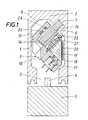
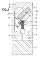
- a tubular protective housing 1 is provided for the measuring system, the ceiling 2 of which is reinforced to form a carrier.
- the housing 1 has a slit-shaped opening 3, which is usually closed by sealing lips (not shown) that press against one another, which extends through a sword-shaped driver 4 of an adjustable part 5, which is coupled to the part whose length or longitudinal displacement is greater than the fixed scale measure is.
- the majority of the scale body 6 protrudes into the cavity 8 of the protective and carrier housing 1 at an angle of 45 °.
- the scale body 6 bears an incremental measurement graduation consisting of fine graduation marks in one track, reference marks being able to be provided in a second track. Incremental measuring graduations are currently being produced with graduation steps down to the micrometer range.
- a scanning unit 9 is used for reading the scale and for generating analog measurement signals from this scanning.
- this scanning unit consists of two main bodies 10, 11, one of which (10) forms ball bearings 12 with two rollers on the lower flat side and the other (11) is supported with two further ball bearings 14 on the lower narrow side of the carrier body.
- the main body 10 can be set relative to the main body 11 with the aid of set screws 13, 15 and can be fixed with further screws after the setting.
- the purpose of this setting is to set an optical lighting device provided on part 10 in relation to receivers attached to part 11.
- the ball bearings 12, 14 are held in engagement by one or more compression springs 16 supported on the driver 4 with the guide surfaces of the scale body 6 formed by the lower front side and the lower narrow side.
- the driver 9 takes the scanning unit 9 longitudinally preferably via permanently engaged permanent magnets or magnet-armature combinations, the sides of which facing each other cross and are arched, so that punctiform contact points arise.
- the lighting device consists of a light-emitting diode 17 which emits a light cone through a pinhole 18.
- the illumination device 17 - 22 illuminates the measuring graduation through the scanning grating, the light passing through the scanning grating and measuring graduation falling through the scale body 6 onto photoelectric receivers 23, 24, 25 mounted in part 11.
- the receivers 23 are intended for the generation of mutually phase-shifted measurement signals, which ideally have the relative phase positions 0 °, 90 °, 180 ° and 270 °. By pair-wise anti-parallel connection of receiver pairs, two output signals which are phase-shifted by 90 ° are normally generated and sent for further processing.
- the receiver 24 is assigned to the reference track of the scale body 6 and is intended for generating a reference pulse when a reference mark is passed.
- the photoelectric receiver 25 serves to detect the average brightness, from which the current performance of the light source can be deduced and by which a decrease in the illuminance of the receivers as a result of aging or contamination can be determined, it also being possible to set a reference level for the reference pulse.
- settings of part 10 relative to part 11 are preferably first made until the maximum at receivers 23-25.
- Signal level occurs.
- the signal level, phase position and signal shape are then set by removing regions of the reflection layer 20, in particular with the aid of a laser beam.
- the reflection layer 20 of the reflector is shown schematically, on which the empirically determined reflection areas, which are assigned to the receivers 23, 24, 25, are indicated by dashed lines in their outlines and are designated by 23 ', 24', 25 '.
- the phase spacing and the signal form of the signals occurring at the photoelectric receivers (23-25) partial areas of the reflection layer are removed in accordance with a predetermined program according to lines 26 in the embodiment according to FIG. 5 with the aid of a computer-controlled laser beam.
- the phase position and also the signal shape can be influenced, for example, by removing the reflection layer in the side edge region of the outlines 23 '.
Landscapes
- Physics & Mathematics (AREA)
- General Physics & Mathematics (AREA)
- Optical Transform (AREA)
- Paper (AREA)
- Length Measuring Devices By Optical Means (AREA)
- Analysing Materials By The Use Of Radiation (AREA)
- Optical Radar Systems And Details Thereof (AREA)
- Mechanical Coupling Of Light Guides (AREA)
Applications Claiming Priority (2)
| Application Number | Priority Date | Filing Date | Title |
|---|---|---|---|
| AT2127/89 | 1989-09-12 | ||
| AT0212789A AT394111B (de) | 1989-09-12 | 1989-09-12 | Inkrementales messsystem |
Publications (3)
| Publication Number | Publication Date |
|---|---|
| EP0418211A2 true EP0418211A2 (fr) | 1991-03-20 |
| EP0418211A3 EP0418211A3 (en) | 1991-11-06 |
| EP0418211B1 EP0418211B1 (fr) | 1994-03-16 |
Family
ID=3528350
Family Applications (1)
| Application Number | Title | Priority Date | Filing Date |
|---|---|---|---|
| EP90890239A Expired - Lifetime EP0418211B1 (fr) | 1989-09-12 | 1990-08-09 | Système de mesure incrémental |
Country Status (4)
| Country | Link |
|---|---|
| US (1) | US5099583A (fr) |
| EP (1) | EP0418211B1 (fr) |
| AT (2) | AT394111B (fr) |
| DE (1) | DE59004998D1 (fr) |
Cited By (2)
| Publication number | Priority date | Publication date | Assignee | Title |
|---|---|---|---|---|
| EP0635701A1 (fr) * | 1993-07-17 | 1995-01-25 | Dr. Johannes Heidenhain GmbH | Dispositif de mesure de longeurs ou d'angles |
| DE19629488A1 (de) * | 1996-07-12 | 1998-01-22 | Huebner Elektromasch Ag | Vorrichtung zum Gewinnen von oberwellenfreien Signalen |
Families Citing this family (4)
| Publication number | Priority date | Publication date | Assignee | Title |
|---|---|---|---|---|
| JP3384519B2 (ja) * | 1995-10-13 | 2003-03-10 | キタムラ機械株式会社 | 工作機械用テーブル装置 |
| US5837981A (en) * | 1997-07-24 | 1998-11-17 | Wang; Chin-Yuan | Signal outputting device of optical ruler |
| GB0807088D0 (en) * | 2008-04-18 | 2008-05-21 | Eley Metrology Ltd | Positioning apparatus |
| DE102011101085A1 (de) * | 2011-05-10 | 2012-11-15 | Lenord, Bauer & Co. Gmbh | Sensoreinrichtung |
Family Cites Families (15)
| Publication number | Priority date | Publication date | Assignee | Title |
|---|---|---|---|---|
| US2720810A (en) * | 1949-01-29 | 1955-10-18 | Kearney & Trecker Corp | Measuring instrument |
| CH409430A (de) * | 1961-05-16 | 1966-03-15 | Oerlikon Buehrle Holding Ag | Einrichtung zum lichtelektrischen Bestimmen der Verschiebung eines Massstabes mit Teilstrichen relativ zu einer Projektionsoptik |
| CH444964A (de) * | 1965-10-02 | 1967-10-15 | Oerlikon Buehrle Holding Ag | Anordnung zur Kompensation veränderlicher Störeinflüsse auf eine strahlungselektrische Mess- oder Steuerstrecke |
| GB1353470A (en) * | 1970-10-19 | 1974-05-15 | Post D | Position measuring apparatus utilizing moire fringe multiplication |
| US3833303A (en) * | 1972-10-06 | 1974-09-03 | Bausch & Lomb | Measuring apparatus using the moire fringe concept of measurement |
| GB1444851A (en) * | 1973-08-07 | 1976-08-04 | Oelsch Fernsteuergeraete | Photoelectric sensor head |
| JPS5635765Y2 (fr) * | 1975-09-22 | 1981-08-24 | ||
| DE2611459C3 (de) * | 1976-03-18 | 1978-09-21 | Dr. Johannes Heidenhain Gmbh, 8225 Traunreut | Längenmeßeinrichtung |
| JPS5522664U (fr) * | 1978-07-31 | 1980-02-14 | ||
| US4499374A (en) * | 1981-06-01 | 1985-02-12 | Mitutoyo Mfg. Co., Ltd. | Photoelectrical encoder employing an optical grating |
| US4549353A (en) * | 1982-07-28 | 1985-10-29 | Mitutoyo Mfg. Co., Ltd. | Displacement measuring instrument |
| DE3311118C2 (de) * | 1983-03-26 | 1986-04-17 | Dr. Johannes Heidenhain Gmbh, 8225 Traunreut | Gekapselte lichtelektrische Meßeinrichtung |
| JPS63217222A (ja) * | 1987-03-06 | 1988-09-09 | Mitsutoyo Corp | 光電式変位検出装置 |
| CH672680A5 (en) * | 1987-06-05 | 1989-12-15 | Mettler Instrumente Ag | Opto-electronic length or angle measurer - achieves comparable light parallelity, higher light yield with sample in more compact design contg. parabolic glass mirror |
| JPS6436021A (en) * | 1987-07-31 | 1989-02-07 | Canon Kk | Microwave plasma processor |
-
1989
- 1989-09-12 AT AT0212789A patent/AT394111B/de not_active IP Right Cessation
-
1990
- 1990-08-09 AT AT90890239T patent/ATE103065T1/de not_active IP Right Cessation
- 1990-08-09 EP EP90890239A patent/EP0418211B1/fr not_active Expired - Lifetime
- 1990-08-09 DE DE90890239T patent/DE59004998D1/de not_active Expired - Fee Related
- 1990-09-07 US US07/579,885 patent/US5099583A/en not_active Expired - Lifetime
Cited By (4)
| Publication number | Priority date | Publication date | Assignee | Title |
|---|---|---|---|---|
| EP0635701A1 (fr) * | 1993-07-17 | 1995-01-25 | Dr. Johannes Heidenhain GmbH | Dispositif de mesure de longeurs ou d'angles |
| US5493399A (en) * | 1993-07-17 | 1996-02-20 | Johannes Heidenhain Gmbh | Position measuring system with compensation for variable distance between light source and index disk |
| DE19629488A1 (de) * | 1996-07-12 | 1998-01-22 | Huebner Elektromasch Ag | Vorrichtung zum Gewinnen von oberwellenfreien Signalen |
| DE19629488C2 (de) * | 1996-07-12 | 1999-11-18 | Huebner Elektromasch Ag | Vorrichtung zum Gewinnen von oberwellenfreien Signalen |
Also Published As
| Publication number | Publication date |
|---|---|
| AT394111B (de) | 1992-02-10 |
| ATA212789A (de) | 1991-07-15 |
| EP0418211A3 (en) | 1991-11-06 |
| EP0418211B1 (fr) | 1994-03-16 |
| DE59004998D1 (de) | 1994-04-21 |
| ATE103065T1 (de) | 1994-04-15 |
| US5099583A (en) | 1992-03-31 |
Similar Documents
| Publication | Publication Date | Title |
|---|---|---|
| DE69133544T2 (de) | Vorrichtung zur Projektion eines Maskenmusters auf ein Substrat | |
| DE68925744T2 (de) | Telezentrisch abbildendes System | |
| AT395914B (de) | Photoelektrische positionsmesseinrichtung | |
| DE3337874C2 (fr) | ||
| DE3507778A1 (de) | Vorrichtung und verfahren zur eichung eines mikroskopischen bearbeitungssystems mit hilfe einer justierplatte | |
| EP0451474A2 (fr) | Procédé et dispositif pour mesurer sans contact le contour superficiel d'un objet | |
| DE19800354A1 (de) | Vorrichtung und Verfahren zur Entfernungsmessung | |
| DE3439540A1 (de) | Verfahren und einrichtung zum bestimmen der projektionsrichtung eines von einer lichtquelle abgegebenen lichtstrahls | |
| EP0019721A1 (fr) | Appareil de projection optique pour l'alignement d'une image de projection sur une surface | |
| DE3719538C2 (fr) | ||
| DE19732668A1 (de) | Vorrichtung und Verfahren zur Kalibrierung von Strahlabtastvorrichtungen | |
| DE1905392A1 (de) | Vorrichtung zum Erzeugen von elektrischen Signalen mittels eines Skalengitters,das relativ zu einem Indexgitter bewegbar ist | |
| EP0418211A2 (fr) | Système de mesure incrémental | |
| DE2615676A1 (de) | Digitalanzeigendes messgeraet, insbesondere streckenmessgeraet | |
| WO1989001147A1 (fr) | Procede pour le controle qualite d'un objet plat, notamment pour la detection de defauts dans des matieres textiles, et dispositif a cet effet | |
| EP0135673B1 (fr) | Procédé et dispositif pour déterminer une coordonnée sur la surface d'un corps solide | |
| DE3245357C2 (de) | Inkrementale Meßeinrichtung | |
| DE3343181C2 (fr) | ||
| DE3312203A1 (de) | Kantendetektor in einem optischen messinstrument | |
| DE7834317U1 (de) | Fluessigkristallanzeigevorrichtung | |
| DE19754867B4 (de) | Spaltabtast-Projektionsbelichtungsgerät und Halbleitereinrichtung | |
| DE102022204539A1 (de) | Verfahren zum Justieren einer Kamera | |
| DE2160282A1 (de) | Automatische Einstellanordnung | |
| DE102020122670A1 (de) | Materialbearbeitungsvorrichtung und Verfahren zum Betreiben einer Materialbearbeitungsvorrichtung | |
| DE102020204536A1 (de) | Laservorrichtung und Verfahren zum Einstellen einer Laservorrichtung |
Legal Events
| Date | Code | Title | Description |
|---|---|---|---|
| PUAI | Public reference made under article 153(3) epc to a published international application that has entered the european phase |
Free format text: ORIGINAL CODE: 0009012 |
|
| AK | Designated contracting states |
Kind code of ref document: A2 Designated state(s): AT BE CH DE FR GB IT LI LU NL SE |
|
| PUAL | Search report despatched |
Free format text: ORIGINAL CODE: 0009013 |
|
| AK | Designated contracting states |
Kind code of ref document: A3 Designated state(s): AT BE CH DE FR GB IT LI LU NL SE |
|
| 17P | Request for examination filed |
Effective date: 19920121 |
|
| 17Q | First examination report despatched |
Effective date: 19930211 |
|
| GRAA | (expected) grant |
Free format text: ORIGINAL CODE: 0009210 |
|
| AK | Designated contracting states |
Kind code of ref document: B1 Designated state(s): AT BE CH DE FR GB IT LI LU NL SE |
|
| PG25 | Lapsed in a contracting state [announced via postgrant information from national office to epo] |
Ref country code: IT Free format text: LAPSE BECAUSE OF FAILURE TO SUBMIT A TRANSLATION OF THE DESCRIPTION OR TO PAY THE FEE WITHIN THE PRE;WARNING: LAPSES OF ITALIAN PATENTS WITH EFFECTIVE DATE BEFORE 2007 MAY HAVE OCCURRED AT ANY TIME BEFORE 2007. THE CORRECT EFFECTIVE DATE MAY BE DIFFERENT FROM THE ONE RECORDED.SCRIBED TIME-LIMIT Effective date: 19940316 Ref country code: SE Free format text: THE PATENT HAS BEEN ANNULLED BY A DECISION OF A NATIONAL AUTHORITY Effective date: 19940316 Ref country code: BE Effective date: 19940316 Ref country code: GB Effective date: 19940316 Ref country code: NL Effective date: 19940316 Ref country code: FR Effective date: 19940316 |
|
| REF | Corresponds to: |
Ref document number: 103065 Country of ref document: AT Date of ref document: 19940415 Kind code of ref document: T |
|
| REF | Corresponds to: |
Ref document number: 59004998 Country of ref document: DE Date of ref document: 19940421 |
|
| EN | Fr: translation not filed | ||
| NLV1 | Nl: lapsed or annulled due to failure to fulfill the requirements of art. 29p and 29m of the patents act | ||
| PG25 | Lapsed in a contracting state [announced via postgrant information from national office to epo] |
Ref country code: LU Free format text: LAPSE BECAUSE OF NON-PAYMENT OF DUE FEES Effective date: 19940831 Ref country code: LI Effective date: 19940831 Ref country code: CH Effective date: 19940831 |
|
| GBV | Gb: ep patent (uk) treated as always having been void in accordance with gb section 77(7)/1977 [no translation filed] |
Effective date: 19940316 |
|
| PLBE | No opposition filed within time limit |
Free format text: ORIGINAL CODE: 0009261 |
|
| STAA | Information on the status of an ep patent application or granted ep patent |
Free format text: STATUS: NO OPPOSITION FILED WITHIN TIME LIMIT |
|
| 26N | No opposition filed | ||
| REG | Reference to a national code |
Ref country code: CH Ref legal event code: PL |
|
| PGFP | Annual fee paid to national office [announced via postgrant information from national office to epo] |
Ref country code: AT Payment date: 20050816 Year of fee payment: 16 |
|
| PG25 | Lapsed in a contracting state [announced via postgrant information from national office to epo] |
Ref country code: AT Free format text: LAPSE BECAUSE OF NON-PAYMENT OF DUE FEES Effective date: 20060809 |
|
| PGFP | Annual fee paid to national office [announced via postgrant information from national office to epo] |
Ref country code: DE Payment date: 20070822 Year of fee payment: 18 |
|
| PG25 | Lapsed in a contracting state [announced via postgrant information from national office to epo] |
Ref country code: DE Free format text: LAPSE BECAUSE OF NON-PAYMENT OF DUE FEES Effective date: 20090303 |