EP0418531A1 - Injektionsschlauch für abzudichtende Fugen in Betonbauwerken - Google Patents
Injektionsschlauch für abzudichtende Fugen in Betonbauwerken Download PDFInfo
- Publication number
- EP0418531A1 EP0418531A1 EP90115064A EP90115064A EP0418531A1 EP 0418531 A1 EP0418531 A1 EP 0418531A1 EP 90115064 A EP90115064 A EP 90115064A EP 90115064 A EP90115064 A EP 90115064A EP 0418531 A1 EP0418531 A1 EP 0418531A1
- Authority
- EP
- European Patent Office
- Prior art keywords
- injection
- hose
- supply hose
- openings
- radial openings
- Prior art date
- Legal status (The legal status is an assumption and is not a legal conclusion. Google has not performed a legal analysis and makes no representation as to the accuracy of the status listed.)
- Granted
Links
- 238000002347 injection Methods 0.000 title claims abstract description 48
- 239000007924 injection Substances 0.000 title claims abstract description 48
- 238000010276 construction Methods 0.000 title 1
- 238000007789 sealing Methods 0.000 title 1
- 239000000463 material Substances 0.000 claims abstract description 11
- 239000007788 liquid Substances 0.000 claims description 15
- 230000002093 peripheral effect Effects 0.000 claims description 2
- 239000012530 fluid Substances 0.000 abstract 1
- 238000004519 manufacturing process Methods 0.000 description 2
- 239000011248 coating agent Substances 0.000 description 1
- 238000000576 coating method Methods 0.000 description 1
- 230000005489 elastic deformation Effects 0.000 description 1
- 239000008267 milk Substances 0.000 description 1
- 210000004080 milk Anatomy 0.000 description 1
- 235000013336 milk Nutrition 0.000 description 1
- 239000002245 particle Substances 0.000 description 1
Images
Classifications
-
- E—FIXED CONSTRUCTIONS
- E04—BUILDING
- E04B—GENERAL BUILDING CONSTRUCTIONS; WALLS, e.g. PARTITIONS; ROOFS; FLOORS; CEILINGS; INSULATION OR OTHER PROTECTION OF BUILDINGS
- E04B1/00—Constructions in general; Structures which are not restricted either to walls, e.g. partitions, or floors or ceilings or roofs
- E04B1/62—Insulation or other protection; Elements or use of specified material therefor
- E04B1/66—Sealings
- E04B1/68—Sealings of joints, e.g. expansion joints
- E04B1/6816—Porous tubular seals for injecting sealing material
Definitions
- the invention relates to an injection hose for joints to be sealed in concrete structures, with a flexible, liquid-impermeable supply hose for injection liquid, which is provided with radial openings in the injection area, and with a casing made of liquid-tight material that fits tightly at least in the injection area.
- Injection hoses of the type mentioned are intended to allow an injection liquid to exit under pressure, while preventing concrete particles or concrete mass from entering the injection hose from the outside.
- the known injection hoses (EP-PS 199 108, DE-GM 84 25 518) work with closure bodies of radial openings which can be compressed under the pressure of the injection liquid and are both with regard to their manufacture and also used materials complex and correspondingly expensive.
- An injection hose with the features mentioned at the outset is also known, the liquid-tight outer shell of which is intended to break open in places under the pressure of the injection liquid. In most cases, this inexpensive injection hose does not guarantee the desired seal, because the outer casing often does not tear open at all or all of the desired points and, moreover, material can penetrate into the injection hose from the outside at the tear points.
- the invention has for its object to design an injection hose of the type mentioned so that it remains inexpensive to manufacture and ensures an escape of injection liquid in the entire injection area.
- the object is achieved with an injection hose of the type mentioned in the present invention in that the circumferential cover consists of an elastically stretchable material which also has radial openings which are offset from the radial openings of the supply hose.
- the radial openings of the tightly fitting, circumferential sheath are each separated from the radial openings of the inner supply hose by contact areas.
- the circumferential casing Under the pressure of the injection liquid, the circumferential casing can be lifted off at the radial openings of the supply hose with elastic deformation, so that the abovementioned contact areas disappear and a passage of the injection liquid escaping from the supply hose through its radial openings under pressure to the radial openings of the outer casing.
- the passage cross-section for injection liquid formed by radial openings of the supply hose per peripheral surface unit of the injection hose can be kept larger than the passage cross-section formed by the openings of the casing, which can be achieved by different opening diameters or by different opening numbers in the supply hose and in the outer casing.
- An injection hose designed according to the invention can be produced at low cost.
- the fitting of the adjacent outer sheath onto the supply hose while avoiding overlap of the radial openings of the two hose structures can be accomplished easily and without great mechanical effort.
- a smaller passage area of the outer casing compared to the passage area of the supply hose favors a uniform injection liquid outlet over the entire hose circumference in the injection area.
- the use of compressible porous closure bodies or coating surfaces is not necessary.
- the injection hose 10 consists of an inner supply hose 11, which is made of a bendable or elastically bendable, liquid-impermeable material, in particular plastic material.
- the supply hose 11 is surrounded by a thin-walled envelope hose 12, which lies tightly against the outside of the supply hose 11 and is made of an elastically stretchable material.
- the supply hose 11 is provided with radial through openings 13 arranged in rows and at a mutual distance from one another.
- the outer jacket tube 12 is also provided with rows and at a distance from each other through openings 14 which are offset from the openings 13 of the supply hose.
- the number of through openings 13, 14 and their distribution over the circumference of the injection hose 10 can be as desired. In the illustrated embodiment, there is a uniform circumferential distribution of the through openings shown.
- the through openings 13 of the supply hose 11 have a larger diameter than the through openings 14 of the enveloping hose 12.
- injection liquid for example concrete milk
- this injection liquid exerts pressure in the area of the through openings 13 of the supply hose 11 on the tightly fitting casing tube 12, under which the casing hose 12 is located at this point due to its can bulge elastic property, as can be seen from Fig. 3.
- connecting spaces 16 are formed between the through openings 13 of the supply hose 11 and the through openings 14 of the enveloping tube 12. Through these connecting spaces 16, the injection liquid reaches the through openings 14 of the outer enveloping tube 12 and exits there, as shown in FIG. 3 by arrows 17 is indicated.
- the outer enveloping hose 12 lies tight against the supply hose 11 again due to its inherent elasticity, so that a backflow of liquid from the outside to the through openings 13 of the liquid-impermeable supply hose 11 is prevented.
Landscapes
- Engineering & Computer Science (AREA)
- Architecture (AREA)
- Physics & Mathematics (AREA)
- Electromagnetism (AREA)
- Civil Engineering (AREA)
- Structural Engineering (AREA)
- Building Environments (AREA)
- Rigid Pipes And Flexible Pipes (AREA)
- On-Site Construction Work That Accompanies The Preparation And Application Of Concrete (AREA)
- Coating Apparatus (AREA)
- Sealing Material Composition (AREA)
- Joints Allowing Movement (AREA)
Abstract
Description
- Die Erfindung betrifft einen Injektionsschlauch für abzudichtende Fugen in Betonbauwerken, mit einem flexiblen, flüssigkeitsundurchlässigen zuleitungsschlauch für Injektionsflüssigkeit, der im Injektionsbereich mit radialen Öffnungen versehen ist, und mit einer den Zuleitungsschlauch mindestens im Injektionsbereich dicht anliegend umfangenden Hülle aus flüssigkeitsdichtem Material.
- Injektionsschläuche der genannten Art sollen einer Injektionsflüssigkeit unter Druck den Austritt erlauben, dagegen den Eintritt von Betonteilchen oder Betonmasse von außen in den Injektionsschlauch verhindern. Die bekannten Injektionsschläuche (EP-PS 199 108, DE-GM 84 25 518) arbeiten mit unter dem Druck der Injektionsflüssigkeit zusammenpreßbaren Verschlußkörpern von Radialöffnungen und sind sowohl hinsichtlich ihrer Herstellung als auch der verwendeten Materialien aufwendig und entsprechend teuer. Es ist zwar auch ein Injektionsschlauch mit den eingangs genannten Merkmalen bekannt, dessen flüssigkeitsdichte Außenhülle unter dem Druck der Injektionsflüssigkeit stellenweise aufbrechen soll. Dieser preiswerte Injektionsschlauch gewährleistet aber in den meisten Fällen nicht die gewünschte Abdichtung, weil die Außenhülle häufig nicht an den oder allen gewünschten Stellen aufreißt und außerdem an den Aufreißstellen Material von außen in den Injektionsschlauch eindringen kann.
- Der Erfindung liegt die Aufgabe zugrunde, einen Injektionsschlauch der genannten Art so auszubilden, daß er preiswert in seiner Herstellung bleibt und einen Austritt von Injektionsflüssigkeit im gesamten Injektionsbereich gewährleistet.
- Die gestellte Aufgabe wird mit einem Injektionsschlauch der eingangs genannten Art erfindungsgemäß dadurch gelöst, daß die umfangende Hülle aus einem elastisch dehnbaren Material besteht, das ebenfalls radiale Öffnungen aufweist, die gegenüber den radialen Öffnungen des Zuleitungsschlauches versetzt angeordnet sind.
- Bei einem erfindungsgemäß ausgebildeten Injektionsschlauch sind die radialen Öffnungen der dicht anliegenden, umfangenden Hülle von den radialen Öffnungen des inneren Zuleitungsschlauches jeweils durch Anlagebereiche getrennt. Unter dem Druck der Injektionsflüssigkeit läßt sich die umfangende Hülle an den radialen Öffnungen des Zuleitungsschlauches unter elastischer Verformung abheben, so daß die vorstehend erwähnten Anlagebereiche verschwinden und ein Durchtritt der aus den Zuleitungsschlauch durch dessen radiale Öffnungen unter Druck äustretenden Injektionsflüssigkeit zu den radialen Öffnungen der außeren Hülle erfolgt. Vorteilhafterweise kann der pro Umfangsflächeneinheit des Injektionsschlauches durch radiale Öffnungen des Zuleitungsschlauches gebildete Durchlaßquerschnitt für Injektionsflüssigkeit größer gehalten sein als der durch die Öffnungen der Hülle gebildete Durchlaßquerschnitt, was durch unterschiedliche Öffnungsdurchmesser oder durch unterschiedliche Öffnungszahlen im Zuleitungsschlauch und in der äußeren Hülle erreichbar ist.
- Ein erfindungsgemäß ausgebildeter Injektionsschlauch läßt sich mit geringen Kostenaufwand herstellen. Das Aufziehen der anliegenden äußeren Hülle auf den Zuleitungsschlauch unter Vermeidung von Überdeckungen der radialen Öffnungen der beiden Schlauchgebilde läßt sich problemlos und ohne großen maschinellen Aufwand bewerkstelligen. Durch eine kleinere Durchlaßfläche der Außenhülle gegenüber der Durchlaßfläche des Zuleitungsschlauches wird ein gleichmäßiger Injektionsflüssigkeitsaustritt über den gesamten Schlauchumfang im Injektionsbereich begünstigt. Der Einsatz von zusammenpreßbaren porösen Verschlußkörpern oder Beschichtungsflächen entfällt.
- Nachfolgend wird ein Ausführungsbeispiel eines erfindungsgemäß ausgebildeten Injektionsschlauches anhand der beiliegenden Zeichnung näher erläutert.
- Im einzelnen zeigen:
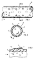
- Fig. 1 eine Seitenansicht eines Abschnittes eines Injektionsschlauches;
- Fig. 2 einen Querschnitt durch den Injektionsschlauch entlang der Linie II-II in Fig. 1;
- Fig. 3 einen Teillängsschnitt durch den Injektionsschlauch entlang der Linie III-III in Fig. 2.
- Wie am besten das Schnittbild der Fig. 2 erkennen läßt, besteht der Injektionsschlauch 10 aus einem inneren Zuleitungsschlauch 11, der aus einem biegbaren oder elastisch biegbaren, flüssigkeitsundurchlässigen Material, insbesondere Kunststoffmaterial, gefertigt ist. Der Zuleitungsschlauch 11 ist von einem dünnwandigeren Hüllschlauch 12 umgeben, der dicht an der Außenseite des Zuleitungsschlauches 11 anliegt und aus einem elastisch dehnbaren Material gefertigt ist. Der Zuleitungsschlauch 11 ist mit reihenweise und mit gegenseitigem Abstand voneinander angeordneten radialen Durchgangsöffnungen 13 versehen. Auch der äußere Hüllschlauch 12 ist mit reihenweise und mit gegenseitigem Abstand voneinander angeordneten Durchlaßöffnungen 14 versehen, die gegenüber den Durchlaßöffnungen 13 des Zuleitungsschlauches versetzt sind. Die Zahl der Durchgangsöffnungen 13, 14 und ihre Verteilung über den Umfang des Injektionsschlauches 10 kann beliebig sein. Beim dargestellten Ausführungsbeispiel ist eine gleichmäßige Umfangsverteilung der Durchgangsöffnungen dargestellt. Außerdem weisen die Durchgangsöffnungen 13 des Zuleitungsschlauches 11 einen größeren Durchmesser auf als die Durchgangsöffnungen 14 des Hüllschlauches 12.
- Wird in den Innenraum 15 des Zuleitungsschlauches 11 Injektionsflüssigkeit, beispielsweise Betonmilch, unter Druck eingeführt, übt diese Injektionsflüssigkeit im Bereich der Durchgangsöffnungen 13 des Zuleitungsschlauches 11 einen Druck auf den dicht anliegenden Hüllschlauch 12 aus, unter welchem sich der Hüllschlauch 12 an dieser Stelle auf Grund seiner elastischen Eigenschaft aufbauchen kann, wie aus Fig. 3 ersichtlich ist. Bei diesem Aufbauchen entstehen Verbindungsräume 16 zwischen den Durchgangsöffnungen 13 des Zuleitungsschlauches 11 und den Durchgangsöffnungen 14 des Hüllschlauches 12. Durch diese Verbindungsräume 16 gelangt die Injektionsflüssigkeit zu den Durchgangsöffnungen 14 des äußeren Hüllschlauches 12 und tritt dort nach außen aus, wie in Fig. 3 durch Pfeile 17 angedeutet ist. Sobald der Druck im Innern 15 des Zuleitungsschlauches 11 beseitigt wird, legt sich der äußere Hüllschlauch 12 auf Grund seiner Eigenelastizität wieder gegen den Zuleitungsschlauch 11 dicht an, so daß ein Rückfluß von Flüssigkeit von außen zu den Durchgangsöffnungen 13 des flüssigkeitsundurchlässigen Zuleitungsschlauches 11 verhindert wird.
Claims (3)
Priority Applications (1)
| Application Number | Priority Date | Filing Date | Title |
|---|---|---|---|
| AT90115064T ATE92561T1 (de) | 1989-09-08 | 1990-08-06 | Injektionsschlauch fuer abzudichtende fugen in betonbauwerken. |
Applications Claiming Priority (2)
| Application Number | Priority Date | Filing Date | Title |
|---|---|---|---|
| DE3929848 | 1989-09-08 | ||
| DE3929848A DE3929848C3 (de) | 1989-09-08 | 1989-09-08 | Injektionsschlauch für abzudichtende Fugen in Betonbauwerken |
Publications (2)
| Publication Number | Publication Date |
|---|---|
| EP0418531A1 true EP0418531A1 (de) | 1991-03-27 |
| EP0418531B1 EP0418531B1 (de) | 1993-08-04 |
Family
ID=6388891
Family Applications (1)
| Application Number | Title | Priority Date | Filing Date |
|---|---|---|---|
| EP90115064A Expired - Lifetime EP0418531B1 (de) | 1989-09-08 | 1990-08-06 | Injektionsschlauch für abzudichtende Fugen in Betonbauwerken |
Country Status (6)
| Country | Link |
|---|---|
| US (1) | US5056282A (de) |
| EP (1) | EP0418531B1 (de) |
| AT (1) | ATE92561T1 (de) |
| DE (3) | DE3929848C3 (de) |
| DK (1) | DK0418531T3 (de) |
| ES (1) | ES2042156T3 (de) |
Cited By (2)
| Publication number | Priority date | Publication date | Assignee | Title |
|---|---|---|---|---|
| EP0524389A1 (de) * | 1991-07-25 | 1993-01-27 | BBZ- BETONBAU- ZUBEHÖRHANDELSGESELLSCHAFT mbH | Injektionsschlauch für Fugen an Bauwerken |
| DE19507087A1 (de) * | 1995-03-01 | 1996-11-14 | Hans Szepanski | Verfahren zum Abdichten von Fugen in Bauwerken mittels eines Dichtungsmittels sowie Schläuche zur Erstellung von Kanälen zum Injizieren von Dichtungsmitteln |
Families Citing this family (27)
| Publication number | Priority date | Publication date | Assignee | Title |
|---|---|---|---|---|
| US5290045A (en) * | 1991-03-01 | 1994-03-01 | C.I. Kasei Co., Ltd. | Seal for joint, and method of installing same seal |
| ATE160837T1 (de) * | 1991-03-01 | 1997-12-15 | Kasei Co C I | Dichtung für eine fuge und verfahren zum einsetzen derselben |
| DE4106839C2 (de) * | 1991-03-04 | 1994-06-30 | Suspa Spannbeton Gmbh | Ventil, insbesondere zur Nachinjektion eines Verpreßankers im Baugrund |
| NO177939C (no) * | 1991-03-19 | 1995-12-20 | Bjarne Sem | Injeksjonsslange for kjemisk injeksjon i betong |
| DE4123067A1 (de) * | 1991-07-12 | 1993-01-14 | Betonbau Zubehoer Handel | Verfahren zum abdichten von fugen an bauwerken |
| DE4215731A1 (de) * | 1992-05-13 | 1993-11-18 | Rene P Schmid | Verfahren zum Errichten von Betonwänden mittels Verschalungen sowie Vorrichtung und Mittel zur Durchführung dieses Verfahrens |
| DE4340845C2 (de) * | 1993-11-26 | 2002-12-19 | Ibs Injektionstechnologie Gmbh | Injektionsprofil zum Abdichten von Fugen an Bauwerken |
| DE19515816C1 (de) * | 1995-04-29 | 1997-02-13 | Gerd Dipl Ing Pleyers | Vorrichtung zur Durchführung eines Bohrlochinjektionsverfahrens |
| DE29612245U1 (de) * | 1996-07-13 | 1996-09-12 | Rehau Ag + Co, 95111 Rehau | Injektionsschlauch |
| DE19632982A1 (de) * | 1996-08-16 | 1998-02-19 | Gbs Grundbau Bohrtechnik Spezi | Injektionsschlauch |
| FR2762892B1 (fr) * | 1997-04-30 | 1999-07-02 | Westaflex Automobile | Tuyau pour le transport de fluides gazeux, notamment dans les automobiles |
| ATE216012T1 (de) | 1997-09-11 | 2002-04-15 | Betomax Kunststoff Metall | Verpressschlauch zum herstellen von wasserundurchlässigen oder nur gering wasserdurchlässigen, gasdichten und/oder kraftschlüssigen bauwerksfugen und verfahren zu seiner herstellung |
| DE29907233U1 (de) | 1999-04-23 | 1999-07-29 | REHAU AG + Co., 95111 Rehau | Schlauch |
| DE29909517U1 (de) | 1999-05-25 | 1999-09-02 | Löffler, Martin, Dipl.-Ing., 15732 Eichwalde | Injektionsprofil zum Abdichten von Bauwerksfugen |
| ATE287010T1 (de) * | 2001-07-02 | 2005-01-15 | Elas Geotecnica Srl | Injektionsventilrohre und ihr herstellungsverfahren |
| US6926037B2 (en) * | 2002-12-17 | 2005-08-09 | Wellstream International Limited | Collapse tolerant flexible pipe and method of manufacturing same |
| DE102010033430A1 (de) | 2010-08-04 | 2012-02-09 | Dmi Injektionstechnik Gmbh | Injektionsschlauch aus flexiblem flüssigkeitsundurchlässigem Werkstoff für abzudichtende Fugen |
| IT1402723B1 (it) | 2010-11-22 | 2013-09-18 | Elas Geotecnica Srl | Valvola di non ritorno per un elemento tubolare di consolidamento |
| DE202013102172U1 (de) | 2013-05-17 | 2013-06-06 | Jürgen Kitzenberger | Abdichtelement für Arbeitsfugen im Stahlbetonbau |
| WO2023205043A1 (en) * | 2022-04-20 | 2023-10-26 | Dupont Safety & Construction, Inc. | Foam envelope for sealing large volumes |
| WO2023205040A1 (en) * | 2022-04-20 | 2023-10-26 | Dupont Safety & Construction, Inc. | Foam envelope for sealing large volumes |
| US12410607B2 (en) * | 2022-04-20 | 2025-09-09 | Ddp Specialty Electronic Materials Us, Llc | Foam envelope for sealing large volumes |
| CN115059057A (zh) * | 2022-08-01 | 2022-09-16 | 中铁一局集团有限公司 | 一种隧道区间道床离缝病害综合整治施工方法 |
| US12492551B2 (en) * | 2023-04-18 | 2025-12-09 | Dupont Safety & Construction, Inc. | Foam envelope for sealing large volumes |
| US12454822B2 (en) * | 2023-04-18 | 2025-10-28 | Ddp Specialty Electronic Materials Us, Llc | Foam envelope for sealing large volumes |
| US12492550B2 (en) * | 2023-04-18 | 2025-12-09 | Dupont Safety & Construction, Inc. | Foam envelope for sealing large volumes |
| US12559935B2 (en) * | 2023-04-18 | 2026-02-24 | Dupont Safety & Construction, Inc. | Foam envelope for sealing large volumes |
Citations (2)
| Publication number | Priority date | Publication date | Assignee | Title |
|---|---|---|---|---|
| JPS57158418A (en) * | 1981-03-27 | 1982-09-30 | Toa Gurauto Kogyo Kk | Strainer unit for injecting chemical agent |
| EP0125696A2 (de) * | 1983-05-17 | 1984-11-21 | Eva-Maria Rasbach | Mehrschichtiger poröser Schlauch |
Family Cites Families (8)
| Publication number | Priority date | Publication date | Assignee | Title |
|---|---|---|---|---|
| DE8425518U1 (de) * | 1984-08-29 | Koob, Kunibert, Ing.(grad.), 4234 Alpen | Injektionsschlauch | |
| US3427810A (en) * | 1966-12-01 | 1969-02-18 | John F Petersen | Method and apparatus for draining water |
| CH643623A5 (de) * | 1980-03-05 | 1984-06-15 | Aquarius Fuer Dichte Bauten Ag | Schlauchartige dichtungsvorrichtung fuer betonfugen. |
| DE8300766U1 (de) * | 1983-01-13 | 1983-06-16 | Koob, Kunibert, Ing.(grad.), 4234 Alpen | Injektionsschlauch fuer arbeitsfiguren an betonbauwerken |
| DE8335231U1 (de) * | 1983-12-08 | 1984-03-08 | De Neef Chemie S.A. N.V., 3100 Heist o/d Berg | Betonfugen-Dichtungsvorrichtung |
| JPS61143128A (ja) * | 1984-12-17 | 1986-06-30 | 芦森工業株式会社 | 管路の内張り材 |
| DE3507806C2 (de) * | 1985-03-05 | 1993-11-18 | Webac Chemie Gmbh | Rohrförmige Dichtungsvorrichtung zum Abdichten von Fugen, insbesondere Betonfugen |
| DE3512470C2 (de) * | 1985-04-04 | 1996-01-04 | Kunibert Ing Grad Koob | Injektionsschlauch für Arbeitsfugen an Betonbauwerken |
-
1989
- 1989-09-08 DE DE3929848A patent/DE3929848C3/de not_active Expired - Fee Related
- 1989-09-08 DE DE8915525U patent/DE8915525U1/de not_active Expired - Lifetime
-
1990
- 1990-08-06 AT AT90115064T patent/ATE92561T1/de not_active IP Right Cessation
- 1990-08-06 ES ES199090115064T patent/ES2042156T3/es not_active Expired - Lifetime
- 1990-08-06 DK DK90115064.9T patent/DK0418531T3/da active
- 1990-08-06 DE DE9090115064T patent/DE59002179D1/de not_active Expired - Lifetime
- 1990-08-06 EP EP90115064A patent/EP0418531B1/de not_active Expired - Lifetime
- 1990-08-23 US US07/572,756 patent/US5056282A/en not_active Expired - Lifetime
Patent Citations (2)
| Publication number | Priority date | Publication date | Assignee | Title |
|---|---|---|---|---|
| JPS57158418A (en) * | 1981-03-27 | 1982-09-30 | Toa Gurauto Kogyo Kk | Strainer unit for injecting chemical agent |
| EP0125696A2 (de) * | 1983-05-17 | 1984-11-21 | Eva-Maria Rasbach | Mehrschichtiger poröser Schlauch |
Cited By (2)
| Publication number | Priority date | Publication date | Assignee | Title |
|---|---|---|---|---|
| EP0524389A1 (de) * | 1991-07-25 | 1993-01-27 | BBZ- BETONBAU- ZUBEHÖRHANDELSGESELLSCHAFT mbH | Injektionsschlauch für Fugen an Bauwerken |
| DE19507087A1 (de) * | 1995-03-01 | 1996-11-14 | Hans Szepanski | Verfahren zum Abdichten von Fugen in Bauwerken mittels eines Dichtungsmittels sowie Schläuche zur Erstellung von Kanälen zum Injizieren von Dichtungsmitteln |
Also Published As
| Publication number | Publication date |
|---|---|
| US5056282A (en) | 1991-10-15 |
| DK0418531T3 (da) | 1993-12-13 |
| DE3929848C3 (de) | 1997-07-17 |
| DE8915525U1 (de) | 1990-09-27 |
| DE3929848A1 (de) | 1991-03-14 |
| ATE92561T1 (de) | 1993-08-15 |
| DE59002179D1 (de) | 1993-09-09 |
| DE3929848C2 (de) | 1992-04-30 |
| EP0418531B1 (de) | 1993-08-04 |
| ES2042156T3 (es) | 1993-12-01 |
Similar Documents
| Publication | Publication Date | Title |
|---|---|---|
| EP0418531A1 (de) | Injektionsschlauch für abzudichtende Fugen in Betonbauwerken | |
| EP0199108B1 (de) | Injektionsschlauch für Arbeitsfugen an Betonbauwerken | |
| EP0751813B1 (de) | Filterelement mit stützkörper | |
| DE2329719A1 (de) | Becherfoermige vorrichtung zum auffangen von menstruationsfluessigkeit zur inneren anwendung | |
| DE69603878T2 (de) | Filterelement für einen flüssigkeitsfilter | |
| DE2846582C2 (de) | Vorrichtung zur Membranfiltration | |
| EP0930928B1 (de) | Filter für flüssigkeiten | |
| EP0215934B1 (de) | Wärmetauscher | |
| DE2817249C2 (de) | Rohrverbindung | |
| DE2536253C3 (de) | Rohrverbindung, insbesondere für Steinzeugrohre | |
| DE3141878C1 (de) | "Dichtungsring für Badewannenablaufventile" | |
| DE10147907B4 (de) | Filtervorrichtung sowie Verfahren zu deren Herstellung | |
| DE3321038C2 (de) | ||
| AT2373U1 (de) | Injektionsschlauch | |
| EP0076350B1 (de) | Vorrichtung zum Überbrücken der Fuge zwischen zwei Teilen einer Dacheindeckung und Verfahren zur Prüfung ihrer Dichtigkeit | |
| EP0098411A2 (de) | Belüftungsfilter | |
| DE8633675U1 (de) | Flaschenzelle | |
| DE3917203C2 (de) | ||
| DE2755176B1 (de) | Reinigungsrohr | |
| DE2451066B2 (de) | Anschluss- oder verschlusselement | |
| DE9315357U1 (de) | Dichtungsanordnung | |
| DE20112799U1 (de) | Flachringdichtung mit Zentrierring | |
| DE8014780U1 (de) | Mehrteiliges filtergehaeuse zur aufnahme von mehreren patronenfoermigen filterelementen | |
| CH676670A5 (de) | ||
| DE8514676U1 (de) | Abzugsrohr aus gewebeverträglichem Kunststoff |
Legal Events
| Date | Code | Title | Description |
|---|---|---|---|
| PUAI | Public reference made under article 153(3) epc to a published international application that has entered the european phase |
Free format text: ORIGINAL CODE: 0009012 |
|
| AK | Designated contracting states |
Kind code of ref document: A1 Designated state(s): AT BE CH DE DK ES FR GB GR IT LI LU NL SE |
|
| 17P | Request for examination filed |
Effective date: 19910614 |
|
| 17Q | First examination report despatched |
Effective date: 19910827 |
|
| GRAA | (expected) grant |
Free format text: ORIGINAL CODE: 0009210 |
|
| AK | Designated contracting states |
Kind code of ref document: B1 Designated state(s): AT BE CH DE DK ES FR GB GR IT LI LU NL SE |
|
| REF | Corresponds to: |
Ref document number: 92561 Country of ref document: AT Date of ref document: 19930815 Kind code of ref document: T |
|
| REF | Corresponds to: |
Ref document number: 59002179 Country of ref document: DE Date of ref document: 19930909 |
|
| GBT | Gb: translation of ep patent filed (gb section 77(6)(a)/1977) |
Effective date: 19930831 |
|
| ITF | It: translation for a ep patent filed | ||
| REG | Reference to a national code |
Ref country code: ES Ref legal event code: FG2A Ref document number: 2042156 Country of ref document: ES Kind code of ref document: T3 |
|
| ET | Fr: translation filed | ||
| EPTA | Lu: last paid annual fee | ||
| REG | Reference to a national code |
Ref country code: DK Ref legal event code: T3 |
|
| REG | Reference to a national code |
Ref country code: GR Ref legal event code: FG4A Free format text: 3009415 |
|
| PLBE | No opposition filed within time limit |
Free format text: ORIGINAL CODE: 0009261 |
|
| 26N | No opposition filed | ||
| PLBI | Opposition filed |
Free format text: ORIGINAL CODE: 0009260 |
|
| 26 | Opposition filed |
Opponent name: WEBAC-CHEMIE GMBH Effective date: 19940503 |
|
| NLR1 | Nl: opposition has been filed with the epo |
Opponent name: WEBAC-CHEMIE GMBH |
|
| EAL | Se: european patent in force in sweden |
Ref document number: 90115064.9 |
|
| PGFP | Annual fee paid to national office [announced via postgrant information from national office to epo] |
Ref country code: LU Payment date: 19950701 Year of fee payment: 6 |
|
| PGFP | Annual fee paid to national office [announced via postgrant information from national office to epo] |
Ref country code: BE Payment date: 19950710 Year of fee payment: 6 Ref country code: SE Payment date: 19950710 Year of fee payment: 6 |
|
| PGFP | Annual fee paid to national office [announced via postgrant information from national office to epo] |
Ref country code: DK Payment date: 19950718 Year of fee payment: 6 |
|
| PGFP | Annual fee paid to national office [announced via postgrant information from national office to epo] |
Ref country code: GB Payment date: 19950727 Year of fee payment: 6 |
|
| PGFP | Annual fee paid to national office [announced via postgrant information from national office to epo] |
Ref country code: GR Payment date: 19950822 Year of fee payment: 6 |
|
| PLBO | Opposition rejected |
Free format text: ORIGINAL CODE: EPIDOS REJO |
|
| PG25 | Lapsed in a contracting state [announced via postgrant information from national office to epo] |
Ref country code: GB Effective date: 19960806 Ref country code: LU Free format text: LAPSE BECAUSE OF NON-PAYMENT OF DUE FEES Effective date: 19960806 Ref country code: DK Effective date: 19960806 |
|
| REG | Reference to a national code |
Ref country code: DK Ref legal event code: EBP |
|
| PG25 | Lapsed in a contracting state [announced via postgrant information from national office to epo] |
Ref country code: SE Effective date: 19960807 |
|
| PLBN | Opposition rejected |
Free format text: ORIGINAL CODE: 0009273 |
|
| STAA | Information on the status of an ep patent application or granted ep patent |
Free format text: STATUS: OPPOSITION REJECTED |
|
| PG25 | Lapsed in a contracting state [announced via postgrant information from national office to epo] |
Ref country code: BE Effective date: 19960831 |
|
| 27O | Opposition rejected |
Effective date: 19960527 |
|
| NLR2 | Nl: decision of opposition | ||
| BERE | Be: lapsed |
Owner name: PFLIEGER GEB. HARM LIESEOTTE Effective date: 19960831 |
|
| PG25 | Lapsed in a contracting state [announced via postgrant information from national office to epo] |
Ref country code: GR Free format text: THE PATENT HAS BEEN ANNULLED BY A DECISION OF A NATIONAL AUTHORITY Effective date: 19970228 |
|
| GBPC | Gb: european patent ceased through non-payment of renewal fee |
Effective date: 19960806 |
|
| REG | Reference to a national code |
Ref country code: GR Ref legal event code: MM2A Free format text: 3009415 |
|
| EUG | Se: european patent has lapsed |
Ref document number: 90115064.9 |
|
| PGFP | Annual fee paid to national office [announced via postgrant information from national office to epo] |
Ref country code: FR Payment date: 20000616 Year of fee payment: 11 |
|
| PGFP | Annual fee paid to national office [announced via postgrant information from national office to epo] |
Ref country code: ES Payment date: 20000810 Year of fee payment: 11 |
|
| PG25 | Lapsed in a contracting state [announced via postgrant information from national office to epo] |
Ref country code: ES Free format text: LAPSE BECAUSE OF NON-PAYMENT OF DUE FEES Effective date: 20010807 |
|
| PG25 | Lapsed in a contracting state [announced via postgrant information from national office to epo] |
Ref country code: FR Free format text: LAPSE BECAUSE OF NON-PAYMENT OF DUE FEES Effective date: 20020430 |
|
| REG | Reference to a national code |
Ref country code: FR Ref legal event code: ST |
|
| REG | Reference to a national code |
Ref country code: ES Ref legal event code: FD2A Effective date: 20020911 |
|
| PGFP | Annual fee paid to national office [announced via postgrant information from national office to epo] |
Ref country code: NL Payment date: 20060831 Year of fee payment: 17 |
|
| PG25 | Lapsed in a contracting state [announced via postgrant information from national office to epo] |
Ref country code: NL Free format text: LAPSE BECAUSE OF NON-PAYMENT OF DUE FEES Effective date: 20080301 |
|
| NLV4 | Nl: lapsed or anulled due to non-payment of the annual fee |
Effective date: 20080301 |
|
| PGFP | Annual fee paid to national office [announced via postgrant information from national office to epo] |
Ref country code: AT Payment date: 20090827 Year of fee payment: 20 Ref country code: DE Payment date: 20090615 Year of fee payment: 20 Ref country code: CH Payment date: 20090713 Year of fee payment: 20 |
|
| PGFP | Annual fee paid to national office [announced via postgrant information from national office to epo] |
Ref country code: IT Payment date: 20090824 Year of fee payment: 20 |
|
| REG | Reference to a national code |
Ref country code: CH Ref legal event code: PL |
|
| PG25 | Lapsed in a contracting state [announced via postgrant information from national office to epo] |
Ref country code: DE Free format text: LAPSE BECAUSE OF EXPIRATION OF PROTECTION Effective date: 20100806 |