EP0418903B2 - Dispositif d'introduction d'une bande de papier pour presse rotative - Google Patents
Dispositif d'introduction d'une bande de papier pour presse rotative Download PDFInfo
- Publication number
- EP0418903B2 EP0418903B2 EP90118149A EP90118149A EP0418903B2 EP 0418903 B2 EP0418903 B2 EP 0418903B2 EP 90118149 A EP90118149 A EP 90118149A EP 90118149 A EP90118149 A EP 90118149A EP 0418903 B2 EP0418903 B2 EP 0418903B2
- Authority
- EP
- European Patent Office
- Prior art keywords
- paper web
- web threading
- threading member
- threading
- path
- Prior art date
- Legal status (The legal status is an assumption and is not a legal conclusion. Google has not performed a legal analysis and makes no representation as to the accuracy of the status listed.)
- Expired - Lifetime
Links
- 238000011176 pooling Methods 0.000 claims abstract description 23
- 238000011144 upstream manufacturing Methods 0.000 claims abstract description 21
- 239000002390 adhesive tape Substances 0.000 description 14
- 238000004026 adhesive bonding Methods 0.000 description 3
- 238000012423 maintenance Methods 0.000 description 3
- 230000008439 repair process Effects 0.000 description 3
- 238000010276 construction Methods 0.000 description 2
- 230000000717 retained effect Effects 0.000 description 2
- 230000015572 biosynthetic process Effects 0.000 description 1
- 238000001514 detection method Methods 0.000 description 1
- 239000013013 elastic material Substances 0.000 description 1
- 238000007689 inspection Methods 0.000 description 1
- 230000002093 peripheral effect Effects 0.000 description 1
- 230000002787 reinforcement Effects 0.000 description 1
- 230000003014 reinforcing effect Effects 0.000 description 1
- 238000004804 winding Methods 0.000 description 1
Images


Classifications
-
- B—PERFORMING OPERATIONS; TRANSPORTING
- B41—PRINTING; LINING MACHINES; TYPEWRITERS; STAMPS
- B41F—PRINTING MACHINES OR PRESSES
- B41F13/00—Common details of rotary presses or machines
- B41F13/02—Conveying or guiding webs through presses or machines
- B41F13/03—Threading webs into printing machines
Definitions
- the invention relates to a paper web threading apparatus according to the preamble of claim 1.
- the threading member is pushed along the threading member guiding path.
- the threading member is a band having a substantially increased thickness at the lateral edges, to be guided between two guiding rods.
- the EP-A 094 631 discloses a threading apparatus having a single cable which is wound around and unwound from a drum 35, to be connected with a web to be threaded.
- a prior art paper web threading apparatus for a rotary printing press is publicly known from, for example, the apparatus disclosed in Japanese Laid-Open Patent Application NO. HEI-1-103647.
- This prior art paper web threading apparatus comprises pipe-shaped guide rails provided with branched portions along a plurality of paper web threading paths and having a longitudinally extending slit formed on one side thereof, the guide rails each having notches formed at appropriate intervals therealong; driving units provided in the notches; running members adapted to be driven by the driving units so as to run on their respective guide rails in zigzag direction and having full length somewhat longer than the spacing between the notches; each of the running members having a clip secured thereto and adapted to detachably hold a paper web connecting adaptor connected to the leading end of printing paper drawn out from a paper web roll disposed at a paper web supply section.
- Threading of a paper web in a rotary printing press is made from the upstream side of a paper web threading path to the downstream side thereof, namely, from a paper web supply section to a folding section.
- the paper web to be threaded along the path is guided by a comparatively short running member (which is referred to as short running member hereinbelow).
- the driving members for driving the short running member are provided at intervals somewhat shorter than the length of the short running member, the short running member is driven by two sets of driving units along some part of the path, and by one set of driving units along the other part thereof so that the driving force exerted on the running member cannot be kept constant.
- Provision of a multiplicity of driving units not only increases the cost of printed matters, but also complicates the narrow interior of the frame of the rotary printing press, and also renders it difficult to carry out ordinary printing operation as well as maintenance/repairs and inspection, thus causing problems in terms of safe operation.
- the present invention has been made in view of the above-mentioned circumstances in the prior art, and has for its object to provide a paper web threading apparatus for a rotary printing press which is capable of threading a paper web through a paper web threading path smoothly, surely and at nearly constant speed without applying an uneven tension to the paper web and whose construction is simple so that the frequency of troubles is limited and maintenance/repairs thereof can be carried out readily and safe operation can be achieved.
- the apparatus according to the invention is characterized by the features of claim 1.
- a paper web threading member pooled in a paper web threading member pooling section is run reversely by a reversely rotating driving unit along a paper web threading member guide from the downstream side of a paper web threading path to an upstream position thereof where a paper web is waiting at a paper web supply section. Subsequently, the paper web is secured to the paper web retaining member of the paper web threading member, and then the driving unit thereof is forwardly rotated to run the paper web threading member along the paper web threading member guide from the upstream side of the path to the downstream side thereof so that the paper web is threaded along the paper web threading member guide.
- the paper web threading apparatus will function as follows.
- a paper web threading member pooled in a paper web threading member pooling section is run reversely by a reversely rotating driving unit along a paper web threading member guide from the downstream side of a paper web threading path to an upstream position where a paper web is waiting at a paper web supply section.
- another paper web threading member pooled in another paper web threading member pooling section is run reversely, in like manner, by another reversely rotating driving unit along another paper web threading member guide from the downstream side thereof to an upstream position somewhat downstream of a position where the paper web is slit longitudinally, and is stopped there.
- the paper web is secured to the paper web retaining member of the former paper web threading member, and then the relevant driving unit is forwardly rotated so as to run the paper web threading member along the paper web threading member guide from the upstream side thereof to the downstream side thereof to thereby thread the paper web through the paper web threading path along the paper web threading member guide.
- the free end of the other one of the divided paper webs is moved forwards by the pushing force applied thereto by the succeeding portion thereof which continues to run downstream, and is guided onto the paper web retaining member of the other paper web threading member which is waiting at a position somewhat downstream of the position where the paper web is slit by the action of the slitter in the longitudinal direction thereof.
- the driving unit for driving the other paper web threading member begins to rotate forwardly so as to commence running of the other paper web threading member along the other paper web threading member guide from the upstream side thereof to the downstream side thereof, and also the automatic retaining member is actuated so as to secure the free end of the other one of the divided paper webs to the paper web retaining member of the other paper web threading member.
- the other one of the divided paper webs is threaded through the paper web threading path along the other paper web threading member guide.
- the present invention even in case the paper web is slit in the longitudinal direction thereof and then the divided paper webs are threaded through their respective paper web threading paths, it is possible to thread the divided paper webs through their respective paper web threading paths smoothly, surely and at nearly constant speed without applying any uneven tension to the paper webs.
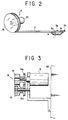
- Fig. 10 shows schematically one embodiment of the printing press to which the present invention is to be applied.
- This printing press includes one or a plurality of paper web supply section(s) S, printing section(s) P and folding section(s) F, which are associated in corporation with one another.
- the paper web threading path is routed by a plurality of guide rolls GR and turning bars TB, etc., and is branched on its way so as to provide predetermined paper web threading paths each extending from the paper web supply section S through the printing section P to the folding section F.
- the paper web threading apparatus for use in such a printing press is useful for drawing out a paper web W from a paper web take-up reel WR installed at each paper web supply section S, select a proper paper threading path extending from the paper web supply section S through the printing section P to the folding section F for obtaining desired printed matters, and threading the paper web along the paper web threading path.
- the concrete configuration of the paper web threading apparatus is as shown in Figs. 1 to 9.
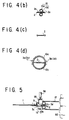
- a paper web threading member guide 10 extends so as to guide a continuous paper web threading member 2 from the paper supply section S (on upstream side) to the folding section F (on downstream side) along the inside of a frame 60 (see Figs. 4(a) and 5) of the printing press and on one side of each of paper web threading paths routed by a plurality of guide rollers GR and turning bars TB.
- the paper web threading member guide 10 is fixedly secured to the above-mentioned frame 60 through the intermediary of brackets 12, for example, as shown in Figs. 4(a) and 5.
- another paper web threading member guide 10' is provided to guide another continuous paper threading member 2' from a place in the vicinity of the position where slitter SL is actuated to the folding section F.
- paper web W 1 one of the divided portions of the paper web W is referred to as “paper web W 1 ", and the other thereof as “paper web W 2 ".
- the paper web threading member guide 10 (10') is comprised of two guide members 10a and 10b located oppositely and in vertically spaced-apart relationship, and the clearance defined between the guide members 10a and 10b is slightly larger than the thickness of the paper web threading member 2 (2'). The arrangement is made such that the paper web threading member 2(2') is slidably moved through the clearance defined between the guide members 10a and 10b.
- the paper web threading member 2 (2') is a continuous, strip-shaped member which is deformable in accordance with the flexure of the paper web threading member guide 10 (10').
- the paper web threading member 2 (2') has two pairs of guide pieces 3a and 3b, and 3c and 3d, respectively, provided on one end thereof in spaced-apart relationship and adapted to be kept in sliding contact with the guide members 10a and 10b of the paper web threading member guide 10 (10′).
- the inner guide piece 3a out of the pair of guide pieces 3a and 3b located on the downstream side of the paper web threading path is connected to one end of a paper web retaining member 1 (1′) through the intermediary of a flexible ribbon 4.
- the other end of the paper web retaining member 1 (1′) is detachably connected to the inner guide piece 3c out of the pair of guide pieces 3c and 3d located on the upstream side in the paper web threading direction through the intermediary of the gripper 5 provided on the guide piece 3c.
- the paper web threading member 2 (2′) has further guide pieces (not shown) provided on both sides thereof and at regular intervals throughout the whole length thereof so as to prevent it from disengaging from the paper web threading member guide 10 (10′).
- the paper web threading member 2 (2′) may be provided with semispherical protrusions 2a, 2a ..., or alternatively it may be formed as a flexible body whose both ends are of a spherical sectional shape as shown in Fig. 4(c).
- a driving unit B adapted to hold the paper web threading member 2 between their guide members 10a and 10b and drive it.
- the driving unit B is constructed as shown in Figs. 1 and 3 and comprises a driving member 13, a driving roller 14 fixedly secured to an output shaft of the driving member 13 and which is made of an elastic material, a driving gear 14a formed as an integral unit of the driving roller 14, an auxiliary roller 15 mounted so as to rotate freely at a position where the paper web threading member 2 (2′) is held between the rollers 14 and 15, and a driven gear 15a formed integrally with the auxiliary roller 15 and which is engaged with the driving gear 14a. Further, one or more of driving unit B may be provided taking into consideration the resistance to running of the paper web threading member 2 (2′).
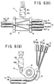
- each of the paper web threading member guides 10 (10′) is provided on the way thereof with appropriate means, such as for example branching C 1 , C 2 , branching means C 2 , joining means C 3 and crossing means C 4 , etc..
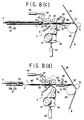
- the branching means C 1 is constructed as shown in Figs. 1 and 6a and arranged such that when piston rods in cylinders 30a and 30b are actuated a branching block 31 can be moved up or down along guides 32, 32 disposed on both sides thereof to thereby select a connection route between the upstream and downstream sides of the branching means C 1 of the paper web threading member guide 10 (10′).
- the branching means C 2 is constructed as shown in Fig. 6(b) and arranged such that when piston rods in cylinders 30c and 30d are actuated a branching block 34 can be turned about a support shaft 35 so as to select a connection route between the upstream and downstream sides of the paper web threading member guide 10 (10′).
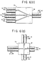
- joining means C 3 is composed of a joining block 36 as shown in Fig. 6c, whilst the crossing means C 4 is comprised of a crossing block 34 as shown in Fig. 6(d) so that the paper web threading member 2 can be guided properly.
- an automatic retaining means D adapted to secure by adhesive-bonding the free end WE′ of the other one of the two portions of the paper web W divided by the slitter SL, namely, the paper web W 2 , onto the paper web retaining member 1′ of another paper web threading member 2′ which stands by downstream of the paper web threading path.
- the automatic retaining means D comprises, as shown in Figs. 7 and 8(a) to 8(d), for example, a stand-by plate 57 for supporting the front portion of the paper web retaining member 1′ when the latter is waiting; guide plates 52, 52′ for guiding the free end WE′ of the paper web W 2 onto the paper web retaining member 1′ which is waiting; an auxiliary plate 53 disposed away from the downstream end of the stand-by plate 57 by a predetermiend space when the paper web retaining member 1′ is waiting on the downstream side of the stand-by plate 57; a holding roller 45 on which a coiled adhesive tape 47 for securing the free end WE′ of the paper web W 2 onto the other paper web retaining member 1′ can be mounted and which is located below the above-mentioned space so as to hold the drawn-out end of the adhesive tape 47; an adhesive tape holder 48 adapted to move the holding roller 45 up and down by means of a hydraulic cylinder 49 relative to the paper web retaining member 1′; a first
- the driving member 13 of the driving section or unit B is reversely rotated to run the paper web threading member 2 (2′), which is inserted between the guide members 10a, 10b of the paper web threading member guide 10 (10′) and held between the driving roller 14 and the auxiliary roller 15 of the driving unit B, from the paper web threading member pooling section A towards the paper web supply section S where the paper web W is waiting (and towards the vicinity of the position where the paper web W is slit in the longitudinal direction thereof, that is, where the aforementioned slitter SL is actuated, towards the upstream side of the paper web threading path, and then stop the paper web threading member 2 (2′) in the condition wherein the paper web retaining member 1 (1′) provided on one end of the member 2 (2′) is run back to a predetermined position where the paper web W is waiting.
- the aforementioned branching means C 1 or C 2 is switched over to select a desired paper web threading path.
- the paper web threading member 2 (2′) is run in the direction opposite to that in the case of threading of the paper web along the paper web threading member guide 10 (10′) located along a desired paper web threading path selected by the branching means C 1 or C 2 .
- This paper web securing operation is made either manually or automatically using an adhesive-bonding means (not shown). Upon completion of the securing, the paper web threading apparatus is ready for threading of the paper web, and then paper web threading is begun.
- the other end of the paper web retaining member 1 (1′) is secured by the gripper 5 to the guide piece 3c.
- threading of the paper web along the path is conducted by rotating forwardly the driving member 13 of the driving unit B so as to run the paper web threading member 2 held between the driving roller 14 and the auxiliary roller 15 of the driving unit B in the direction opposite to that when the operation for preparation of threading is made, that is, towards the down stream side of the paper web threading path.
- This causes the paper web to run together with the paper web threading member 2 along the paper web threading member guide 10 and by way of the aforementioned guide rollers GR and turning bars, etc. to the folding section F.
- the slitter SL is rendered operative at its actuating position to slit the paper web W longitudinally, and one of the divided paper webs, namely, the paper web W 1 which is secured to the paper web retaining member 1 of the paper web threading member 2 at the paper web supply section S is continuously threaded through the path as it is, whilst the free end WE′ of the other one of the divided paper webs, namely, the paper web W 2 is secured by the action of the automatic retaining means D, which will be described in detail later, onto a paper web retaining member 1′ of another paper web threading member 2′ which is waiting downstream of the slitter's actuating position. After that, the other paper web threading member 2′ which is waiting downstream of the path is run along the other paper web threading member guide 10′ in the same manner as that in the
- the other end of the paper web retaining member 1 (1′) is detached from the guide piece 3c and is connected flexibly by the flexible ribbon 4 to the paper web threading member 2 (2′).
- the other paper web threading member 2′ is sent from the folding section F to the other paper web threading member guide 10′ whose one end is located downstream of the slitter SL as mentioned above.
- the paper web retaining member 1′ held by the gripper 5 is placed on the stand-by plate 57 located on one side of the paper web threading member guide 10′ and the gripper 5 is placed immediately below the release cam 55, the running of the paper web threading member 2′ is stopped by the detection of a sensor (not shown).
- the hydraulic cylinder 56 is actuated so that the gripper 5 is released by the pushing force applied by the release cam 55.
- the paper web retaining member 1′ remains on the stand-by plate 57 and stands ready for threading of the paper web.
- the driving member 13 of the driving unit B is actuated so as to move the other paper web threading member 2′ to the downstream side of the path along the other paper web threading member guide 10′ together with the paper web retaining member 1′ connected thereto by the intermediary of the flexible ribbon 4.
- This movement of the paper web retaining member 1′ allows the adhesive tape 47 to be drawn out continuously around the peripheral surface of the above-mentioned holding roller 45 and to secure by its adhesion the free end WE′ of the paper web W 2 to the paper web retaining member 1′. At that time, for the purpose of reinforcement of the paper web W 2 , a proper length of the tape 47 is adhesively bonded onto the side edge of the paper web W 2 .
- the hydraulic cylinder 49 Upon adhesive bonding of a proper length of the adhesive tape 47 onto the side edge of the other paper web W 2 as mentioned above, the hydraulic cylinder 49 is returned to its original position so as to move the holding roller 45 away from the paper web W 2 . Subsequently, the piston rod in the hydraulic cylinder 51 is extended so as to render the cutter 50 operative to cut off the adhesive tape 47 which is strained between the paper web W 2 and the holding roller 45.
- the free end WE′ of the paper web W 2 is secured automatically by means of the adhesive tape 47 to the paper web retaining member 1′, and the paper web W 2 is threaded through the paper web threading path as mentioned above.
- control of the whole operation of threading of the paper web is performed by a proper controlling system.
- the present invention is not to be limited to the arrangement of the above-mentioned embodiment, and any form or arrangement thereof is applicable provided that the threading of paper web can be conducted by sending back a continuous paper web threading member from the downstream side of the paper web threading path to the upstream side thereof, securing the paper web to the paper web threading member, and then running the latter to the downstream side of the path.
- stripe-shaped paper web threading member 2 (2′) is used in the above-mentioned embodiment, a rope-shaped, cord-shaped or chain-shaped and elongated continuous flexible one may be used as the member 2 (2′). As a further alternative, one which has a different shape on the way thereof may be used.
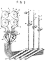
- paper web threading member pooling sections A are gathered into a group Z so as to correspond to their respective paper web threading paths as shown in Figs. 9 and 10, then the paper web threading efficiency can be improved.
- the paper web threading member pooling section group Z by moving paper web threading member pooling sections A together with the relevant auxiliary guides 10 by a proper means (not shown) in any of the directions shown by arrows X, the paper web threading member pooling sections A, A ... can be connected sequentially and/or as desired to any selected ones out of the paper web threading member guides 10, 10 ..., the number of which is more than the number of the paper web threading member pooling sections A, A ....
- the paper web threading member pooling section A should be of the type comprised of a take-up reel 26 provided with a take-up torque generator means 25 as illustrated in the embodiment shown in the drawings.
- a member of the type adapted to be merely pulled back and whose one end is kept free may be used.
- each of the guide members 10a and 10b of the paper web threading member 2 (2′) is not to be limited to the circular type as shown in Figs. 4(b) and 5, and instead the member 2 (2′) may be U-shaped, semi-circular, flat-plate shaped, or T-shaped. Still further, winding of the paper web threading member 2 round the reel 26 of the paper web threading member pooling section A may be conducted by directly driving the reel 26 by a proper means.
- the automatic retaining or securing means D it is possible to secure the free end WE′ of the paper web W 2 onto the paper web retaining member 1′ and supply the adhesive tape for reinforcing the paper web W 2 from the side of the pusher arm 42, and also use double-coated adhesive tape.
- paper web threading apparatus according to the present invention is intended to involve any changes in the design thereof which do not depart from the annexed claims of the invention.
Landscapes
- Engineering & Computer Science (AREA)
- Mechanical Engineering (AREA)
- Replacement Of Web Rolls (AREA)
- Rotary Presses (AREA)
Claims (4)
- Dispositif d'introduction d'une bande de papier dans une presse rotative, comprenantun guide (10, 10') d'entraínement pour une bande de papier agencé le long d'une trajectoire d'enfilage d'une presse rotative et s'étendant depuis un poste d'alimentation (S) qui délivre du papier en bande jusqu'à un emplacement situé immédiatement en amont d'un poste de pliage (F);un organe (2, 2') d'enfilage de la bande de papier s'étendant sur toute la longueur de la trajectoire d'enfilage du papier à partir de son extrémité amont, et qui se meut le long du guide (10, 10') pendant l'opération d'enfilage;un organe préhensile (1, 1') agencé sur l'organe d'enfilage (2, 2') pour saisir la bande de papier à introduire le long de la trajectoire d'enfilage du papier, et au moins une unité d'entraínement (B) pour entraíner l'organe d'enfilage le long du guide (10, 10'), caractérisé par
une unité (A) d'emmagasinage disposée en aval de la trajectoire d'enfilage du papier, afin d'emmagasiner la partie antérieure d'un organe d'enfilage dont l'extrémité postérieure est reliée à une bande de papier, plusieurs unités d'emmagasinage (A) d'organes d'enfilage étant réunies en un groupe (Z) et mobiles pour pouvoir relier au choix les organes d'enfilage à l'un quelconque parmi plusieurs guides d'entraínement (10, 10'). - Dispositif d'introduction d'une bande de papier selon la revendication 1, caractérisé en ce que le guide (10, 10') d'entraínement de la bande de papier comporte des embranchements de séparation et/ou de jonction (C3, 31, 34) le long de sa trajectoire.
- Dispositif d'introduction d'une bande de papier selon une des revendications précédentes, caractérisé en ce quela bande introduite le long de la trajectoire d'enfilage est fendue longitudinalement en au moins deux parties (W1, W2) en un emplacement prédéterminé de la trajectoire, de manière à ce que chacune des deux parties (W1, W2) de la bande de papier puisse être enfilée le long de sa propre trajectoire d'enfilage;un premier guide d'entraínement (10) s'étendant le long d'une trajectoire d'enfilage de la presse rotative, depuis un poste d'alimentation (S) jusqu'à un emplacement situé immédiatement en amont d'un poste de pliage (F);un second guide d'entraínement (10') s'étendant le long d'une trajectoire d'enfilage de la presse rotative, depuis un emplacement proche de l'endroit où le papier est fendu longitudinalement jusqu'à un emplacement situé immédiatement en amont d'un autre poste de pliage (F);deux unités (A, Z) d'emmagasinage étant prévues, une en aval de chacune des trajectoires d'enfilage;au moins deux organes d'enfilage (2, 2') dont chacun s'étend au début de l'opération d'enfilage sur toute la longueur d'une trajectoire d'enfilage, depuis son point situé le plus en amont jusqu'à une des unités d'emmagasinage (A, Z), chacun de ces organes étant déplacé au cours de l'enfilage le long d'un guide (10, 10') vers l'unité d'emmagasinage correspondante;un premier et un second organe préhensile (1, 1') étant prévus sur les organes d'enfilage pour saisir chacun une des bandes de papier séparées (W1, W2) afin de les enfiler dans leurs trajectoires respectives;au moins une unité d'entraínement (B) étant prévue par organe d'enfilage afin de mouvoir celui-ci le long du guide (10, 10') correspondant; etun dispositif de saisie automatique (D) étant disposé à l'extrémité amont du second guide (10') et agencé pour relier automatiquement l'extrémité antérieure d'au moins une des parties (W1, W2) de la bande de papier audit second organe préhensile (1') qui attend en sa position située le plus en amont.
- Dispositif d'introduction d'une bande de papier selon la revendication 3, caractérisé par des embranchements de jonction et/ou de séparation (34) situés sur le parcours du premier guide (10) et/ou du second guide (10').
Applications Claiming Priority (6)
| Application Number | Priority Date | Filing Date | Title |
|---|---|---|---|
| JP24168189 | 1989-09-20 | ||
| JP1241681A JPH0759453B2 (ja) | 1989-09-20 | 1989-09-20 | 輪転機の紙通し装置 |
| JP241681/89 | 1989-09-20 | ||
| JP30280789 | 1989-11-21 | ||
| JP302807/89 | 1989-11-21 | ||
| JP1302807A JPH0688695B2 (ja) | 1989-11-21 | 1989-11-21 | 輪転機の紙通し装置 |
Publications (4)
| Publication Number | Publication Date |
|---|---|
| EP0418903A2 EP0418903A2 (fr) | 1991-03-27 |
| EP0418903A3 EP0418903A3 (en) | 1991-07-31 |
| EP0418903B1 EP0418903B1 (fr) | 1994-12-28 |
| EP0418903B2 true EP0418903B2 (fr) | 2000-05-24 |
Family
ID=26535385
Family Applications (1)
| Application Number | Title | Priority Date | Filing Date |
|---|---|---|---|
| EP90118149A Expired - Lifetime EP0418903B2 (fr) | 1989-09-20 | 1990-09-20 | Dispositif d'introduction d'une bande de papier pour presse rotative |
Country Status (6)
| Country | Link |
|---|---|
| US (1) | US5052295A (fr) |
| EP (1) | EP0418903B2 (fr) |
| AT (1) | ATE116205T1 (fr) |
| AU (1) | AU637823B2 (fr) |
| CA (1) | CA2025552C (fr) |
| DE (1) | DE69015530T3 (fr) |
Cited By (1)
| Publication number | Priority date | Publication date | Assignee | Title |
|---|---|---|---|---|
| CN100522610C (zh) | 2004-03-26 | 2009-08-05 | 柯尼格及包尔公开股份有限公司 | 将材料带或带束牵引到折页机内的装置和方法 |
Families Citing this family (38)
| Publication number | Priority date | Publication date | Assignee | Title |
|---|---|---|---|---|
| JPH0445937A (ja) * | 1990-06-13 | 1992-02-14 | Tokyo Kikai Seisakusho Ltd | ウエブ料紙切断位置調整装置 |
| JPH0688696B2 (ja) * | 1990-08-28 | 1994-11-09 | 株式会社東京機械製作所 | ウェブ料紙加工機械の紙通し装置 |
| JPH0657578B2 (ja) * | 1990-12-13 | 1994-08-03 | 株式会社東京機械製作所 | 紙通し装置 |
| JPH0757658B2 (ja) * | 1991-04-11 | 1995-06-21 | 株式会社東京機械製作所 | 紙通しにおける紙通し体とウェブ料紙との貼り合わせ方法及び貼り合わせ装置 |
| DE4130678C2 (de) * | 1991-09-14 | 1995-03-16 | Roland Man Druckmasch | Vorrichtung zum Einziehen von Bahnen in Rollenrotationsdruckmaschinen |
| FR2684042B1 (fr) * | 1991-11-26 | 1996-06-07 | Heidelberg Harris Sa | Dispositif d'engagement de bande pour presse a imprimer a bobine. |
| DE4202713C2 (de) * | 1992-01-31 | 1993-11-04 | Koenig & Bauer Ag | Fuehrung zum einziehen einer materialbahn in eine rollenrotationsdruckmaschine |
| DE4409693C1 (de) * | 1994-03-22 | 1995-09-21 | Roland Man Druckmasch | Vorrichtung zum Einziehen von Bedruckstoffbahnen über Wendestangen |
| US5947361A (en) * | 1996-07-25 | 1999-09-07 | Emo Elektromotorenwerk Kamenz Gmbh | Apparatus for transporting fabrics and web-shaped material with an electric drive device |
| JP2849679B2 (ja) * | 1996-09-25 | 1999-01-20 | 株式会社東京機械製作所 | 輪転機の紙通しガイドの分岐装置 |
| DE19724123A1 (de) * | 1997-06-09 | 1998-12-10 | Voith Sulzer Papiermasch Gmbh | Vorrichtung und Verfahren zum Überführen eines Einfädelstreifens oder einer Materialbahn |
| FR2765144B1 (fr) * | 1997-06-27 | 1999-09-17 | Heidelberger Druckmasch Ag | Dispositif d'engagement de bandes pour machines rotatives a imprimer |
| DE19754106B4 (de) * | 1997-12-05 | 2004-04-29 | Man Roland Druckmaschinen Ag | Vorrichtung und Verfahren zum Einziehen einer Bedruckstoffbahn |
| DE19757978A1 (de) * | 1997-12-24 | 1999-07-08 | Koenig & Bauer Ag | Vorrichtung zum Einziehen einer Warenbahn |
| DE19758535A1 (de) * | 1997-12-24 | 1999-07-01 | Koenig & Bauer Ag | Vorrichtung zum Antrieb einer Warenbahnleitwalze |
| JP3075408B1 (ja) * | 1999-08-16 | 2000-08-14 | 株式会社東京機械製作所 | ターンバー部の自動紙通し装置 |
| JP2001240280A (ja) | 2000-01-14 | 2001-09-04 | Heidelberger Druckmas Ag | 輪転印刷機に材料ウエブを引き込むための装置 |
| DE10001342A1 (de) * | 2000-01-14 | 2001-07-19 | Heidelberger Druckmasch Ag | Vorrichtung zum Einziehen einer Materialbahn in eine Rotationsdruckmaschine |
| US6398094B1 (en) | 2000-05-08 | 2002-06-04 | The Washington Post | Web threading apparatus for a rotary printing press |
| DE50109595D1 (de) * | 2000-07-13 | 2006-06-01 | Goss Int Montataire Sa | Einrichtung zum Einführen von Materialbahnen in Förderpfade von Rotationsdruckmaschinen |
| DE10106946A1 (de) * | 2001-02-15 | 2002-08-22 | Heidelberger Druckmasch Ag | Einzugselement zum Einziehen einer Materialbahn |
| DE10121945B4 (de) * | 2001-05-05 | 2007-04-05 | Koenig & Bauer Ag | Vorrichtung zum Einziehen einer Materialbahn |
| DE10219264B4 (de) * | 2001-05-05 | 2004-03-25 | Koenig & Bauer Ag | Vorrichtung zum Einziehen einer Materialbahn |
| DE10121943B4 (de) * | 2001-05-05 | 2005-04-21 | Koenig & Bauer Ag | Weiche einer Transportvorrichtung |
| DE10128821B4 (de) * | 2001-06-15 | 2005-07-07 | Koenig & Bauer Ag | Verfahren und Vorrichtung zum Zusammenführen von Materialbahnen |
| DE10152523B4 (de) * | 2001-10-24 | 2005-10-06 | Koenig & Bauer Ag | Einzugmittel zum Einziehen einer Materialbahn |
| FI114995B (fi) * | 2002-04-30 | 2005-02-15 | Metso Paper Inc | Menetelmä ja laitteisto paperirainan pään viemiseksi paperin jälkikäsittelykoneessa |
| DE10361171A1 (de) * | 2003-12-22 | 2005-07-28 | Hauni Maschinenbau Ag | Transport eines Hüllstreifens der Tabak verarbeitenden Industrie |
| DE102004006232B3 (de) | 2004-02-09 | 2005-07-21 | Koenig & Bauer Ag | Verfahren und Vorrichtung zum Einziehen einer Materialbahn |
| DE102004033036A1 (de) * | 2004-03-26 | 2005-10-20 | Koenig & Bauer Ag | Falzapparat mit einem Oberbau und Verfahren zum Einziehen von Bahnsträngen bzw. einer Materialbahn in einen Falzapparat |
| DE102004022541B4 (de) * | 2004-05-05 | 2013-12-05 | Manroland Web Systems Gmbh | Vorrichtung zum Einziehen von Materialbahnen in Aggregate von Rotationsdruckmaschinen |
| DE102005045039B3 (de) * | 2005-09-21 | 2006-12-21 | Koenig & Bauer Ag | Führungseinrichtungen |
| DE102007002875B4 (de) * | 2007-01-15 | 2019-10-10 | Manroland Goss Web Systems Gmbh | Einziehvorrichtung zum Einziehen einer Bedruckstoffbahn in eine Druckmaschine |
| DE102008018840A1 (de) * | 2008-04-15 | 2009-10-22 | Manroland Ag | Vorrichtung zur Be- und/-oder Verarbeitung von bahnförmigem Material |
| DE102008001227B3 (de) | 2008-04-17 | 2009-07-30 | Koenig & Bauer Aktiengesellschaft | Vorrichtung zum Durchführen einer Einziehvorrichtung durch eine Engstelle einer Rollenrotationsdruckmaschine |
| DE202019101925U1 (de) | 2018-07-03 | 2019-04-10 | Mapateq Gmbh | Vorrichtung zum Fördern einer Materialbahn |
| IT202000018088A1 (it) * | 2020-07-27 | 2022-01-27 | Koerber Tissue S P A | Una macchina per lavorare un materiale nastriforme con un dispositivo di incorsatura e relativi metodi |
| DE102024129031B3 (de) * | 2024-10-08 | 2025-11-20 | Mapateq Gmbh | Einfädelvorrichtung für eine Materialbahn |
Family Cites Families (20)
| Publication number | Priority date | Publication date | Assignee | Title |
|---|---|---|---|---|
| US3127079A (en) * | 1964-03-31 | Method for threading the leading end of a weblike material | ||
| US2944345A (en) * | 1958-01-30 | 1960-07-12 | Time Inc | Drive mechanism for web threading apparatus |
| JPS4836325B1 (fr) * | 1970-04-30 | 1973-11-02 | ||
| CH554800A (de) * | 1972-08-22 | 1974-10-15 | Maschf Augsburg Nuernberg Ag | Vorrichtung zum einziehen von materialbahnen in eine rotationsdruckmaschine. |
| DE2402768C2 (de) * | 1974-01-22 | 1978-04-20 | Maschinenfabrik Augsburg-Nuernberg Ag, 8900 Augsburg | Vorrichtung zum Einziehen von Materialbahnen in Rotationsdruckmaschinen |
| US4070965A (en) * | 1974-05-06 | 1978-01-31 | Maschinenfabrik Wifag | Sequential rotary printing press web threading means |
| DE2532168C3 (de) * | 1975-07-18 | 1981-10-29 | Koenig & Bauer AG, 8700 Würzburg | Verfahren und Vorrichtung zum Einziehen einer Papierbahn in Rollenrotationsdruckmaschinen |
| US4063505A (en) * | 1975-07-21 | 1977-12-20 | Ikegsi Iron Works, Ltd. | Papering apparatus in rotary printing press |
| US4078487A (en) * | 1977-03-23 | 1978-03-14 | Baldwin-Korthe Web Controls Inc. | Control method and control for a web processing machine |
| DE8011068U1 (de) * | 1980-04-23 | 1980-07-17 | M.A.N.-Roland Druckmaschinen Ag, 6050 Offenbach | Einzugsvorrichtung fuer rollen- rotationsdruckmaschinen |
| US4308798A (en) * | 1980-07-25 | 1982-01-05 | Carlton Bruce E | Newsprint press orientation device |
| US4480801A (en) * | 1982-05-13 | 1984-11-06 | Motter Printing Press Co. | Webbing system |
| DE3309121C1 (de) * | 1983-03-15 | 1984-08-16 | M.A.N.- Roland Druckmaschinen AG, 6050 Offenbach | Einrichtung zum Befestigen einer Materialbahn an dem Mitnehmer einer Bahneinzugsvorrichtung |
| GB8611722D0 (en) * | 1986-05-14 | 1986-06-25 | Drg Uk Ltd | Processing paper & other webs |
| US4815220A (en) * | 1986-07-18 | 1989-03-28 | Beloit Corporation | Web transfer apparatus |
| US4747254A (en) * | 1987-01-02 | 1988-05-31 | Lantech, Inc. | Web threading device |
| US4854053A (en) * | 1987-04-30 | 1989-08-08 | Beloit Corporation | Transfer apparatus |
| DE3725634A1 (de) * | 1987-08-03 | 1989-02-16 | Roland Man Druckmasch | Rollenkette fuer eine papierbahneinzugsvorrichtung einer druckmaschine |
| JPH0739646Y2 (ja) * | 1988-08-15 | 1995-09-13 | ハマダ印刷機械株式会社 | ターンバー部の自動紙通し装置 |
| US4904344A (en) * | 1989-04-17 | 1990-02-27 | Beloit Corporation | Automatic web threading apparatus and method |
-
1990
- 1990-09-17 CA CA002025552A patent/CA2025552C/fr not_active Expired - Fee Related
- 1990-09-18 AU AU62638/90A patent/AU637823B2/en not_active Ceased
- 1990-09-18 US US07/584,228 patent/US5052295A/en not_active Expired - Lifetime
- 1990-09-20 AT AT90118149T patent/ATE116205T1/de not_active IP Right Cessation
- 1990-09-20 EP EP90118149A patent/EP0418903B2/fr not_active Expired - Lifetime
- 1990-09-20 DE DE69015530T patent/DE69015530T3/de not_active Expired - Fee Related
Cited By (1)
| Publication number | Priority date | Publication date | Assignee | Title |
|---|---|---|---|---|
| CN100522610C (zh) | 2004-03-26 | 2009-08-05 | 柯尼格及包尔公开股份有限公司 | 将材料带或带束牵引到折页机内的装置和方法 |
Also Published As
| Publication number | Publication date |
|---|---|
| AU637823B2 (en) | 1993-06-10 |
| CA2025552C (fr) | 1993-12-21 |
| AU6263890A (en) | 1991-03-28 |
| EP0418903B1 (fr) | 1994-12-28 |
| EP0418903A3 (en) | 1991-07-31 |
| DE69015530D1 (de) | 1995-02-09 |
| ATE116205T1 (de) | 1995-01-15 |
| EP0418903A2 (fr) | 1991-03-27 |
| DE69015530T3 (de) | 2000-11-23 |
| US5052295A (en) | 1991-10-01 |
| CA2025552A1 (fr) | 1991-03-21 |
| DE69015530T2 (de) | 1995-05-11 |
Similar Documents
| Publication | Publication Date | Title |
|---|---|---|
| EP0418903B2 (fr) | Dispositif d'introduction d'une bande de papier pour presse rotative | |
| US4480801A (en) | Webbing system | |
| JPH07108741B2 (ja) | 輪転機の紙通し装置 | |
| US5060878A (en) | Unrolling device | |
| US4111122A (en) | Method of and apparatus for threading web material preferably into web-fed rotary printing presses | |
| JP2815310B2 (ja) | 印刷機械に材料ロールを引き込む引き込み装置およびその方法 | |
| US5405099A (en) | Web-slitting apparatus with driven pinch and windup rollers for varying web tension | |
| JP4006024B2 (ja) | 印刷装置及び印刷方法 | |
| JPS6322452A (ja) | ウエブ送り機の中へウエブを引入れる装置 | |
| US6038973A (en) | Web infeeding or threading device for rotary printing presses | |
| HU214713B (hu) | Rákelszerkezet rotációs mélynyomógéphez | |
| FI69439B (fi) | Foerfarande och anordning foer att forsla banans aenda | |
| US6729573B2 (en) | Roll changer and process for automatic roll change during stoppage | |
| JPH0688695B2 (ja) | 輪転機の紙通し装置 | |
| EP0001605B1 (fr) | Dispositif pour enrouler un film en un rouleau | |
| JPH1067450A (ja) | 紙ウエブの巻取り方法および巻取り装置 | |
| JP4317240B2 (ja) | 輪転機の紙通し方法及び輪転機の紙通し装置 | |
| JP4445455B2 (ja) | ラベリングマシン用テープの引き出し装置およびラベリングマシン | |
| JPH0759453B2 (ja) | 輪転機の紙通し装置 | |
| JPH08216363A (ja) | 自動紙通し装置のウェブ送り装置 | |
| US6769359B2 (en) | Paper-web holding apparatus for rotary printing press | |
| KR101285243B1 (ko) | 디지털 인쇄용 피출력물 공급회수장치 | |
| SU1694465A1 (ru) | Перемоточный станок | |
| US20050269379A1 (en) | Apparatus for threading webs into units of rotary presses | |
| WO2008145655A1 (fr) | Presse à impression rotative offset |
Legal Events
| Date | Code | Title | Description |
|---|---|---|---|
| PUAI | Public reference made under article 153(3) epc to a published international application that has entered the european phase |
Free format text: ORIGINAL CODE: 0009012 |
|
| AK | Designated contracting states |
Kind code of ref document: A2 Designated state(s): AT CH DE GB LI SE |
|
| PUAL | Search report despatched |
Free format text: ORIGINAL CODE: 0009013 |
|
| AK | Designated contracting states |
Kind code of ref document: A3 Designated state(s): AT CH DE GB LI SE |
|
| 17P | Request for examination filed |
Effective date: 19911009 |
|
| 17Q | First examination report despatched |
Effective date: 19930422 |
|
| GRAA | (expected) grant |
Free format text: ORIGINAL CODE: 0009210 |
|
| AK | Designated contracting states |
Kind code of ref document: B1 Designated state(s): AT CH DE GB LI SE |
|
| REF | Corresponds to: |
Ref document number: 116205 Country of ref document: AT Date of ref document: 19950115 Kind code of ref document: T |
|
| REF | Corresponds to: |
Ref document number: 69015530 Country of ref document: DE Date of ref document: 19950209 |
|
| PLBI | Opposition filed |
Free format text: ORIGINAL CODE: 0009260 |
|
| 26 | Opposition filed |
Opponent name: KBA KOENIG & BAUER-ALBERT AG WERK WUERZBURG Effective date: 19950926 |
|
| PLBF | Reply of patent proprietor to notice(s) of opposition |
Free format text: ORIGINAL CODE: EPIDOS OBSO |
|
| PLBF | Reply of patent proprietor to notice(s) of opposition |
Free format text: ORIGINAL CODE: EPIDOS OBSO |
|
| PLAW | Interlocutory decision in opposition |
Free format text: ORIGINAL CODE: EPIDOS IDOP |
|
| APAC | Appeal dossier modified |
Free format text: ORIGINAL CODE: EPIDOS NOAPO |
|
| APAE | Appeal reference modified |
Free format text: ORIGINAL CODE: EPIDOS REFNO |
|
| APAC | Appeal dossier modified |
Free format text: ORIGINAL CODE: EPIDOS NOAPO |
|
| PLAB | Opposition data, opponent's data or that of the opponent's representative modified |
Free format text: ORIGINAL CODE: 0009299OPPO |
|
| R26 | Opposition filed (corrected) |
Opponent name: KOENIG & BAUER AG Effective date: 19950926 |
|
| APAC | Appeal dossier modified |
Free format text: ORIGINAL CODE: EPIDOS NOAPO |
|
| PLAW | Interlocutory decision in opposition |
Free format text: ORIGINAL CODE: EPIDOS IDOP |
|
| RIC2 | Information provided on ipc code assigned after grant |
Free format text: 7B 41F 13/02 A, 7B 41F 13/03 B |
|
| PUAH | Patent maintained in amended form |
Free format text: ORIGINAL CODE: 0009272 |
|
| STAA | Information on the status of an ep patent application or granted ep patent |
Free format text: STATUS: PATENT MAINTAINED AS AMENDED |
|
| 27A | Patent maintained in amended form |
Effective date: 20000524 |
|
| AK | Designated contracting states |
Kind code of ref document: B2 Designated state(s): AT CH DE GB LI SE |
|
| REG | Reference to a national code |
Ref country code: CH Ref legal event code: AEN Free format text: AUFRECHTERHALTUNG DES PATENTES IN GEAENDERTER FORM |
|
| EN | Fr: translation not filed | ||
| REG | Reference to a national code |
Ref country code: GB Ref legal event code: IF02 |
|
| PGFP | Annual fee paid to national office [announced via postgrant information from national office to epo] |
Ref country code: AT Payment date: 20020910 Year of fee payment: 13 |
|
| PGFP | Annual fee paid to national office [announced via postgrant information from national office to epo] |
Ref country code: GB Payment date: 20020918 Year of fee payment: 13 |
|
| PGFP | Annual fee paid to national office [announced via postgrant information from national office to epo] |
Ref country code: DE Payment date: 20020925 Year of fee payment: 13 |
|
| PGFP | Annual fee paid to national office [announced via postgrant information from national office to epo] |
Ref country code: SE Payment date: 20020926 Year of fee payment: 13 |
|
| PGFP | Annual fee paid to national office [announced via postgrant information from national office to epo] |
Ref country code: CH Payment date: 20020927 Year of fee payment: 13 |
|
| PG25 | Lapsed in a contracting state [announced via postgrant information from national office to epo] |
Ref country code: GB Free format text: LAPSE BECAUSE OF NON-PAYMENT OF DUE FEES Effective date: 20030920 Ref country code: AT Free format text: LAPSE BECAUSE OF NON-PAYMENT OF DUE FEES Effective date: 20030920 |
|
| PG25 | Lapsed in a contracting state [announced via postgrant information from national office to epo] |
Ref country code: SE Free format text: LAPSE BECAUSE OF NON-PAYMENT OF DUE FEES Effective date: 20030921 |
|
| PG25 | Lapsed in a contracting state [announced via postgrant information from national office to epo] |
Ref country code: LI Free format text: LAPSE BECAUSE OF NON-PAYMENT OF DUE FEES Effective date: 20030930 Ref country code: CH Free format text: LAPSE BECAUSE OF NON-PAYMENT OF DUE FEES Effective date: 20030930 |
|
| PG25 | Lapsed in a contracting state [announced via postgrant information from national office to epo] |
Ref country code: DE Free format text: LAPSE BECAUSE OF NON-PAYMENT OF DUE FEES Effective date: 20040401 |
|
| EUG | Se: european patent has lapsed | ||
| GBPC | Gb: european patent ceased through non-payment of renewal fee |
Effective date: 20030920 |
|
| REG | Reference to a national code |
Ref country code: CH Ref legal event code: PL |
|
| APAH | Appeal reference modified |
Free format text: ORIGINAL CODE: EPIDOSCREFNO |