EP0419261A1 - Méthode et appareil d'introduction dans un conteneur d'une suspension ou solution de produit dans un propulseur sous pression - Google Patents
Méthode et appareil d'introduction dans un conteneur d'une suspension ou solution de produit dans un propulseur sous pression Download PDFInfo
- Publication number
- EP0419261A1 EP0419261A1 EP90310306A EP90310306A EP0419261A1 EP 0419261 A1 EP0419261 A1 EP 0419261A1 EP 90310306 A EP90310306 A EP 90310306A EP 90310306 A EP90310306 A EP 90310306A EP 0419261 A1 EP0419261 A1 EP 0419261A1
- Authority
- EP
- European Patent Office
- Prior art keywords
- propellant
- suspension
- container
- filling head
- solution
- Prior art date
- Legal status (The legal status is an assumption and is not a legal conclusion. Google has not performed a legal analysis and makes no representation as to the accuracy of the status listed.)
- Granted
Links
- 239000003380 propellant Substances 0.000 title claims abstract description 68
- 239000000725 suspension Substances 0.000 title claims abstract description 55
- 239000000463 material Substances 0.000 title claims abstract description 46
- 238000000034 method Methods 0.000 title claims abstract description 19
- 238000004891 communication Methods 0.000 claims abstract description 8
- LVGUZGTVOIAKKC-UHFFFAOYSA-N 1,1,1,2-tetrafluoroethane Chemical group FCC(F)(F)F LVGUZGTVOIAKKC-UHFFFAOYSA-N 0.000 claims description 2
- KUVIULQEHSCUHY-XYWKZLDCSA-N Beclometasone Chemical group C1CC2=CC(=O)C=C[C@]2(C)[C@]2(Cl)[C@@H]1[C@@H]1C[C@H](C)[C@@](C(=O)COC(=O)CC)(OC(=O)CC)[C@@]1(C)C[C@@H]2O KUVIULQEHSCUHY-XYWKZLDCSA-N 0.000 claims description 2
- NDAUXUAQIAJITI-UHFFFAOYSA-N albuterol Chemical group CC(C)(C)NCC(O)C1=CC=C(O)C(CO)=C1 NDAUXUAQIAJITI-UHFFFAOYSA-N 0.000 claims description 2
- 229950000210 beclometasone dipropionate Drugs 0.000 claims description 2
- 239000003814 drug Substances 0.000 claims description 2
- 239000012530 fluid Substances 0.000 claims description 2
- 229960002052 salbutamol Drugs 0.000 claims description 2
- 239000000126 substance Substances 0.000 claims 2
- CXKWCBBOMKCUKX-UHFFFAOYSA-M methylene blue Chemical compound [Cl-].C1=CC(N(C)C)=CC2=[S+]C3=CC(N(C)C)=CC=C3N=C21 CXKWCBBOMKCUKX-UHFFFAOYSA-M 0.000 claims 1
- 239000000443 aerosol Substances 0.000 description 8
- 239000007788 liquid Substances 0.000 description 7
- 230000006835 compression Effects 0.000 description 3
- 238000007906 compression Methods 0.000 description 3
- 238000009835 boiling Methods 0.000 description 2
- 230000000694 effects Effects 0.000 description 2
- 238000004140 cleaning Methods 0.000 description 1
- 239000012141 concentrate Substances 0.000 description 1
- 239000000203 mixture Substances 0.000 description 1
- -1 or low pressure Substances 0.000 description 1
- 238000004064 recycling Methods 0.000 description 1
- 238000007789 sealing Methods 0.000 description 1
Images


Classifications
-
- B—PERFORMING OPERATIONS; TRANSPORTING
- B65—CONVEYING; PACKING; STORING; HANDLING THIN OR FILAMENTARY MATERIAL
- B65B—MACHINES, APPARATUS OR DEVICES FOR, OR METHODS OF, PACKAGING ARTICLES OR MATERIALS; UNPACKING
- B65B31/00—Packaging articles or materials under special atmospheric or gaseous conditions; Adding propellants to aerosol containers
- B65B31/003—Adding propellants in fluid form to aerosol containers
Definitions
- This invention relates to a method and apparatus for introducing into a container a material to be dispensed in aerosol form and a propellant therefor.
- the invention is particularly concerned with the introduction of pharmaceutical materials into containers, and the following description concentrates on this. It is to be understood, however, that the invention can also be applied to other materials.
- pharmaceutical materials which are to be dispensed in aerosol form are usually suspended in a mixture of at least two propellants, at least one of which has a high enough boiling point to be liquid at room temperature, and at least one of which has a low enough boiling point to be a gas at room temperature.
- a liquid, or low pressure, propellant, and a gaseous, or high pressure, propellant are referred to below as a liquid, or low pressure, propellant, and a gaseous, or high pressure, propellant respectively.
- the pharmaceutical material is first suspended in the liquid propellant by a mixing operation.
- Each aerosol container is then partly filled with this suspension.
- a quantity of the gaseous propellant is then introduced into each of the containers using either a cold-fill method or a high-pressure method.
- the filling operation is carried out at a temperature sufficiently below room temperature for the gaseous propellant to be liquid.
- Each container is then closed by a closure which includes an outlet valve through which the contents of the container can subsequently be dispensed.
- the closure is applied to the container before the gaseous propellant is introduced, and that propellant is introduced subsequently into each container by forcing it under pressure into the container through the outlet valve, which during this operation acts in effect as an inlet valve.
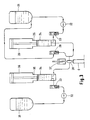
- FIGS. 1 and 2 of the accompanying drawings show diagrammatically a typical known apparatus for introducing into a container a pharmaceutical material and a two-component propellant system.
- FIG. 1 shows the introduction into a container C of a suspension of a pharmaceutical material in a liquid propellant.
- Vessel 1 contains a bulk supply of this suspension which is pumped by a pump 2, through a non-return valve 3, into a metering cylinder 4 provided with a vent 5. From there, the suspension passes to a filling head 8. In the inoperative condition the suspension passes through the head 8 to a non-return valve 9 and thence back to the vessel. The suspension is thus kept constantly in circulation.
- the container is positioned below the head 8, and the valves 3 and 9 are closed.
- the pneumatic cylinder 6 is then operated to force the piston therein downwardly, thus increasing the pressure in the suspension trapped between the valves 3 and 9 to a level sufficiently to open a valve in filling head 8 and to cause suspension to pass from the filling head into the container C.
- the valves 3 and 9 are then opened and the valve in filling head 8 shut, and when the piston in the cylinder 6 is withdrawn to its original position the cylinder 4 refills from the vessel 1. Movement of the filling nozzle into and out of engagement with each can is effected by a piston and cylinder arrangement 7.
- the filling head 8 is arranged to operate only when it is in engagement with a container C.
- the apparatus of Figure 1 introduces into container C a suspension of pharmaceutical material in a liquid propellant, and after an aerosol valve is crimped on the can C the apparatus shown in Figure 2 operates on it to introduce gaseous propellant.
- the apparatus of Figure 2 is formed of components which are substantially the same in principle as corresponding components of Figure 1, except that there is nothing corresponding to the non-return valve 9 and there is no recycling. Components in Figure 2 are denoted by reference numerals which correspond to those used in Figure 1, with the addition of 10.
- the vessel 11 contains gaseous propellant only, under sufficient pressure for it to to be a liquid, and contains no pharmaceutical material.
- a method of introducing into a container a suspension or solution of a material in a propellant held under pressure which comprises bringing a filling head into communication with the container; introducing a quantity of such suspension or solution into the container through the filling head; introducing a quantity of high pressure propellant without any of the said material into the filling head while it is still in communication with the container, thereby to flush through any suspension or solution remaining in the filling head; and withdrawing the filling head from the container.
- an apparatus for introducing into a container a suspension or solution of a material in a propellant held under pressure which comprises a filling head adapted to be brought into and out of communication with the container; means for supplying to the filling head a quantity of the said suspension or solution; and means for supplying to the filling head a quantity of high pressure propellant without any of the said material, the filling head being so arranged that the flow of propellant without any of the said material flushes out any suspension or solution remaining in the filling head.
- the invention also provides a filling head for use in introducing into a container a suspension or solution of a material in a propellant held under pressure, comprising an outlet adapted to communicate, in use, with the container; first and second inlets each communicating with the said outlet via a common flow path, through which inlets, in use, propellant containing the said material, and high pressure propellant not containing the said material, are respectively introduced; and means for selectively closing the first and second inlets so that fluid entering either inlet cannot flow out of the other.
- the propellant without the suspension or solution is the same propellant as that in which the material is held.
- the propellant is 1,1,1,2-tetrafluoroethane (also known as propellant "134a").
- the material being filled into the container is a pharmaceutical substance, for example salbutamol or beclomethasone dipropionate.
- the apparatus according to the invention shown in Figure 3 comprises, in effect, something resembling a combination of the apparatus of Figures 1 and 2, but with a common filling head of a novel design.
- the components shown in Figure 3 are denoted by reference numerals which correspond to those shown in Figure 1, but with the addition of 20 or 30.
- the vessel 21 contains a suspension of a pharmaceutical material in a high-pressure propellant
- the vessel 31 contains a supply of the same propellant alone, i.e. without any pharmaceutical material suspended therein.
- the vessel 31 here contains the same propellant, a different high pressure propellant can of course be used.
- vessel 21 might contain a solution of the pharmaceutical material, instead of a suspension.
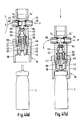
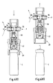
- Figures 4A-4D show in more detail, and on a larger scale, the filling head 28 used in the apparatus of Figure 3.
- the head comprises a substantially cylindrical body 40, the lower end of which is adapted, in use, to engage over the upper end of an aerosol container C.
- a tubular member 43 is mounted for slidable movement within the body 40.
- the tubular member 43 has a wide base portion 44, a narrower body portion 45 and a still narrower neck portion 46.
- “wide” and “narrow” refer to diameters.
- the neck portion 46 of the tubular member 43 penetrates the base of an inverted cup 47, the wall of which surrounds the body portion 45. The body portion 45 can thus slide into the cup 47.
- the base portion 44 of the tubular member abuts an inwardly extending lip 50 of the body 40.
- An outwardly extending lip 51 of the cup 47 rests on an internal shoulder 52 of the body 40.
- a tubular pillar 55 is threadedly engaged with the body 40 such that its lower edge engages on the lip 51 of the cup 47.
- the pillar 55 thus fits around the wall of the cup 47.
- a ring 56 is screwed into the pillar 55 so that it is mounted above the cup 47.
- the neck portion 46 of the tubular member 43 just enters into the ring 56.
- a sliding seal 58 is fitted between the ring 56 and the neck portion 46.
- Rubber O-ring seals 59, 60 are also provided between the ring 56 and the pillar 55 and in the base portion 44 of the member 43, where the nozzle of the container C fits (see later).
- the ring 56 defines an upwardly tapering seat 62 for a correspondingly shaped plug 63.
- the plug 63 is biassed into the seat by a compression spring 64, the upper end of which acts against an inwardly directed lip 65 of the pillar 55.
- Inlet pipes 72,73 are fitted into the inlets 69,70 respectively, sealed therein by O-ring seals 74,74′.
- a ball-bearing 75 which can close against either O-ring seal 74,74′ to form a valve. As explained below, the ball bearing 75 is either forced against the O-ring 74 to seal the inlet 69 or against the O-ring 74′ to seal the inlet 70.
- the pillar 55 provides a circular seat for a piston (not shown) which acts to press the fitting head down onto the container C.
- the inlet 69 is connected to the line which carries the suspension from the metering cylinder 24 to the non-return valve 29.
- the inlet 70 is connected to the outlet of the metering cylinder 34 which contains propellant.
- suspension S flows along the line from the metering cylinder 24 to the non-return valve 29 without entering the interior of the pillar 55, being prevented from doing so by the ball bearing valve 75, forced against the O-ring 74 by the over-pressure of propellant P in the line from cylinder 34.
- the valves 23 ard 29 are closed and the cylinder 26 operated to cause the piston therein to move downwardly.
- the next stage in the filling of the container is to pass a quantity of propellant without any pharmaceutical material suspended therein into the head 28, through the interior of the pillar 55 and of the tubular member 43, and thence into the container. This is done by closing the valve 33 and operating the pneumatic cylinder 36. The increase in the pressure of the propellant which this causes is sufficient to move the ball bearing valve 75. Propellant is unable to pass from the now open inlet 70 to the inlet 69 because of the ball bearing valve 75 which is forced against O-ring 74. This position is shown in Figure 4C.
- Figure 5 shows an alternative embodiment of a filling head 28 to be used in the apparatus of Figure 3.
- the head shown in Figure 5 comprises a substantially cylindrical body 80, the lower end of which is adapted, in use, to engage over the upper end of an aerosol container (not shown in this figure).
- a ring 81 is mounted for longitudinal sliding movement within the body 80 and has an inwardly directed flange 82 on which rests the lower end of a tubular member 83.
- the upper portion of the tubular member 83 is surrounded by an inverted cup 84.
- the cup 84 is in turn surrounded by the annular lower portion of a pillar 85.
- the annular portion is screw threaded into the body 80 to retain the cup 84 in place and sealing is provided by an O-ring seals 86 and a sliding seal 87.
- the tubular member 83 is urged into engagement with the flange 82 by a compression spring 88, the upper end of which bears against a face of the cup 84.
- the pillar 85 has a pair of opposed inlets 89 and 90.
- the inlet 89 is connected to the line which carries suspension from the metering cylinder 24 to the non-return valve 29.
- the inlet 90 is connected to the outlet of the metering cylinder 34 which contains propellant.
- the inlets 89 and 90 communicate with the interior of the tubular member 83 via respective poppet valves 91 and 92 which are biassed by compression springs 93 and 94 into their closed positions.
- suspension flows along the line from the metering cylinder 24 to the non-return valve 29 without entering the interior of the tubular member 83, being prevented from doing so by the valve 91.
- the valves 23 and 29 are closed, and the cylinder 26 operated to cause the piston therein to move downwardly.
- the increase in pressure in the suspension in the metering cylinder 24 which is caused by this is sufficient to overcome the force of the spring 93 holding the valve 91 shut, and suspension is thus able to flow from the inlet 89, through the interior of the tubular member 83, into the container.
- the valve 92 remains closed, and indeed the effectiveness of the seal which it provides is increased by the head 95 of the valve 91 engaging the head 96 of the valve 92. Thus, suspension is unable to pass from the inlet 89 to the inlet 90 and contaminate the inlet 90.
- the next stage in the filling of the container is to pass a quantity of propellant without any pharmaceutical material suspended therein into the head 28, through the tubular member 83, and thence into the container. This is done by closing the valve 33 and operating the pneumatic cylinder 36. The increase in the pressure of the propellant which this causes is sufficient to open the valve 92 to permit propellant through the head 28. Propellant is unable to pass from the inlet 90 to the inlet 89 because of the action of the valve 91.
- this embodiment also provides that when the head 28 is lifted from the aerosol container after the filling operation has been completed, such material as escapes from the lower end of the head consists substantially entirely of propellant, and no pharmaceutical material escapes.
Landscapes
- Chemical & Material Sciences (AREA)
- Dispersion Chemistry (AREA)
- Engineering & Computer Science (AREA)
- Mechanical Engineering (AREA)
- Vacuum Packaging (AREA)
- Containers And Packaging Bodies Having A Special Means To Remove Contents (AREA)
- Medicinal Preparation (AREA)
- Application Of Or Painting With Fluid Materials (AREA)
- Basic Packing Technique (AREA)
- Colloid Chemistry (AREA)
- Filling Or Discharging Of Gas Storage Vessels (AREA)
- Diaphragms For Electromechanical Transducers (AREA)
- Filling Of Jars Or Cans And Processes For Cleaning And Sealing Jars (AREA)
- Feeding, Discharge, Calcimining, Fusing, And Gas-Generation Devices (AREA)
- Agricultural Chemicals And Associated Chemicals (AREA)
Priority Applications (1)
| Application Number | Priority Date | Filing Date | Title |
|---|---|---|---|
| AT90310306T ATE90053T1 (de) | 1989-09-21 | 1990-09-20 | Verfahren und vorrichtung zum einfuehren eines in einem treibmittel unter druck suspendierten oder geloesten produkts in einen behaelter. |
Applications Claiming Priority (2)
| Application Number | Priority Date | Filing Date | Title |
|---|---|---|---|
| GB8921337 | 1989-09-21 | ||
| GB898921337A GB8921337D0 (en) | 1989-09-21 | 1989-09-21 | Method and apparatus |
Publications (2)
| Publication Number | Publication Date |
|---|---|
| EP0419261A1 true EP0419261A1 (fr) | 1991-03-27 |
| EP0419261B1 EP0419261B1 (fr) | 1993-06-02 |
Family
ID=10663409
Family Applications (1)
| Application Number | Title | Priority Date | Filing Date |
|---|---|---|---|
| EP90310306A Expired - Lifetime EP0419261B1 (fr) | 1989-09-21 | 1990-09-20 | Méthode et appareil d'introduction dans un conteneur d'une suspension ou solution de produit dans un propulseur sous pression |
Country Status (14)
| Country | Link |
|---|---|
| EP (1) | EP0419261B1 (fr) |
| JP (1) | JP2809852B2 (fr) |
| AT (1) | ATE90053T1 (fr) |
| AU (1) | AU634817B2 (fr) |
| CA (1) | CA2025779C (fr) |
| DE (1) | DE69001793T2 (fr) |
| DK (1) | DK0419261T3 (fr) |
| ES (1) | ES2043290T3 (fr) |
| FI (1) | FI92171C (fr) |
| GB (2) | GB8921337D0 (fr) |
| HK (1) | HK82397A (fr) |
| IE (1) | IE63939B1 (fr) |
| NZ (1) | NZ235401A (fr) |
| ZA (1) | ZA907534B (fr) |
Cited By (8)
| Publication number | Priority date | Publication date | Assignee | Title |
|---|---|---|---|---|
| EP0564421A3 (fr) * | 1992-04-01 | 1993-10-20 | Patrizia Corona | Dispositif de remplissage de bombes aérosols à air comprimé |
| WO1993023313A1 (fr) * | 1992-05-18 | 1993-11-25 | Birchmeier & Cie. Ag | Bombe aerosol |
| DE4423916A1 (de) * | 1994-07-07 | 1996-02-01 | Boehringer Ingelheim Kg | Verfahren zur Druckabfüllung |
| EP0894722A1 (fr) * | 1997-07-23 | 1999-02-03 | Adolf Würth GmbH & Co. KG | Unité de distribution pour le remplissage de récipients de type aérosol |
| US6786023B2 (en) | 1998-04-21 | 2004-09-07 | Astrazeneca Ab | Method and apparatus for filling containers |
| US6820658B2 (en) | 1998-04-21 | 2004-11-23 | Astrazeneca Ab | Method and apparatus for filling containers |
| EP2384301A4 (fr) * | 2009-06-09 | 2013-10-16 | Surface Technologies Ip Ag | Appareil et procédé de recharge d'un récipient rechargeable |
| CN109095419A (zh) * | 2018-06-21 | 2018-12-28 | 上海西西艾尔启东日用化学品有限公司 | 一种二氧化碳气雾剂制造系统和工艺 |
Families Citing this family (12)
| Publication number | Priority date | Publication date | Assignee | Title |
|---|---|---|---|---|
| FR2669616B1 (fr) * | 1990-11-23 | 1993-01-08 | Atochem | Procede de remplissage de futs par des liquides non miscibles et ses applications, notamment a l'enfutage du phosphore blanc. |
| GB9306292D0 (en) * | 1993-03-26 | 1993-05-19 | Glaxo Group Ltd | Method |
| DE9422052U1 (de) * | 1994-01-04 | 1997-10-30 | Adolf Würth GmbH & Co. KG, 74653 Künzelsau | Befüllgerät zum Befüllen eines wiederbefüllbaren Ausgabebehälters und wiederbefüllbarer Ausgabebehälter |
| AU713925B2 (en) * | 1994-01-04 | 1999-12-16 | Adolf Wurth Gmbh & Co. Kg | A filling device for a refillable distributing container and process for filling the distributing container |
| DE4429161A1 (de) * | 1994-01-04 | 1995-07-06 | Adolf Wuerth Gmbh & Co Kg | Wiederbefüllbarer Ausgabebehälter, Befüllgerät und Verfahren zum Befüllen des Ausgabebehälters |
| DE19513886A1 (de) * | 1995-04-19 | 1996-10-24 | Willi Georg Pfeiffer | Wiederbefüllbare Aerosoldose |
| DE19717080C2 (de) * | 1996-12-19 | 2001-12-06 | Manfred Stadler | Wiederholt nachfüllbare Spraydose oder -flasche |
| DE20103988U1 (de) * | 2001-03-07 | 2001-07-12 | Seaquist Perfect Dispensing GmbH, 44319 Dortmund | Abfüllkopf zur Befüllung von Behältern mit einem fluidförmigen Medium |
| WO2011070690A1 (fr) * | 2009-12-09 | 2011-06-16 | 東洋エアゾール工業株式会社 | Dispositif de remplissage d'agent propulseur |
| DE102013206543A1 (de) * | 2012-07-16 | 2014-01-16 | Robert Bosch Gmbh | Vorrichtung zum Befüllen von Behältnissen |
| CN103879944B (zh) * | 2012-12-19 | 2016-04-20 | 昆山晶科微电子材料有限公司 | 氢氟酸灌装系统 |
| US20200247029A1 (en) * | 2015-12-14 | 2020-08-06 | Khs Corpoplast Gmbh | Method and apparatus for producing liquid-contents-filled containers from preforms by contents being introduced into the preform under pressure |
Citations (3)
| Publication number | Priority date | Publication date | Assignee | Title |
|---|---|---|---|---|
| US3583446A (en) * | 1968-06-24 | 1971-06-08 | Frank E Rush Jr | Process and apparatus for loading containers |
| US3636993A (en) * | 1968-12-31 | 1972-01-25 | Ciba Geigy Corp | Adapter for filling head for filling aerosol dispenser |
| US3642035A (en) * | 1970-07-17 | 1972-02-15 | Ciba Geigy Corp | Device for the filling of dispersers of the aerosol type having a separate self-contained propulsion unit |
Family Cites Families (3)
| Publication number | Priority date | Publication date | Assignee | Title |
|---|---|---|---|---|
| JPS5323008A (en) * | 1976-08-16 | 1978-03-03 | Matsushita Electric Ind Co Ltd | C ommutatorless motor |
| JPS5820486Y2 (ja) * | 1978-02-24 | 1983-04-28 | 凸版印刷株式会社 | 充填ノズル |
| HU189881B (en) * | 1984-01-06 | 1986-04-28 | Pamper, Viktor, Hu | Method for spreading bulk materials from closed space and apparatus for charging the material or materials to be spread into closed space and for pressurizing same |
-
1989
- 1989-09-21 GB GB898921337A patent/GB8921337D0/en active Pending
-
1990
- 1990-09-20 IE IE340790A patent/IE63939B1/en not_active IP Right Cessation
- 1990-09-20 FI FI904627A patent/FI92171C/fi active IP Right Grant
- 1990-09-20 NZ NZ235401A patent/NZ235401A/xx unknown
- 1990-09-20 EP EP90310306A patent/EP0419261B1/fr not_active Expired - Lifetime
- 1990-09-20 DE DE9090310306T patent/DE69001793T2/de not_active Expired - Lifetime
- 1990-09-20 DK DK90310306.7T patent/DK0419261T3/da active
- 1990-09-20 CA CA002025779A patent/CA2025779C/fr not_active Expired - Lifetime
- 1990-09-20 GB GB9020501A patent/GB2236146B/en not_active Expired - Lifetime
- 1990-09-20 AT AT90310306T patent/ATE90053T1/de not_active IP Right Cessation
- 1990-09-20 AU AU63011/90A patent/AU634817B2/en not_active Expired
- 1990-09-20 ES ES90310306T patent/ES2043290T3/es not_active Expired - Lifetime
- 1990-09-20 JP JP2251675A patent/JP2809852B2/ja not_active Expired - Lifetime
- 1990-09-20 ZA ZA907534A patent/ZA907534B/xx unknown
-
1997
- 1997-06-19 HK HK82397A patent/HK82397A/xx not_active IP Right Cessation
Patent Citations (3)
| Publication number | Priority date | Publication date | Assignee | Title |
|---|---|---|---|---|
| US3583446A (en) * | 1968-06-24 | 1971-06-08 | Frank E Rush Jr | Process and apparatus for loading containers |
| US3636993A (en) * | 1968-12-31 | 1972-01-25 | Ciba Geigy Corp | Adapter for filling head for filling aerosol dispenser |
| US3642035A (en) * | 1970-07-17 | 1972-02-15 | Ciba Geigy Corp | Device for the filling of dispersers of the aerosol type having a separate self-contained propulsion unit |
Cited By (9)
| Publication number | Priority date | Publication date | Assignee | Title |
|---|---|---|---|---|
| EP0564421A3 (fr) * | 1992-04-01 | 1993-10-20 | Patrizia Corona | Dispositif de remplissage de bombes aérosols à air comprimé |
| US5375632A (en) * | 1992-04-01 | 1994-12-27 | Corona; Patrizia | Compressed air aerosol bombs of improved type and apparatus for refilling the same |
| WO1993023313A1 (fr) * | 1992-05-18 | 1993-11-25 | Birchmeier & Cie. Ag | Bombe aerosol |
| DE4423916A1 (de) * | 1994-07-07 | 1996-02-01 | Boehringer Ingelheim Kg | Verfahren zur Druckabfüllung |
| EP0894722A1 (fr) * | 1997-07-23 | 1999-02-03 | Adolf Würth GmbH & Co. KG | Unité de distribution pour le remplissage de récipients de type aérosol |
| US6786023B2 (en) | 1998-04-21 | 2004-09-07 | Astrazeneca Ab | Method and apparatus for filling containers |
| US6820658B2 (en) | 1998-04-21 | 2004-11-23 | Astrazeneca Ab | Method and apparatus for filling containers |
| EP2384301A4 (fr) * | 2009-06-09 | 2013-10-16 | Surface Technologies Ip Ag | Appareil et procédé de recharge d'un récipient rechargeable |
| CN109095419A (zh) * | 2018-06-21 | 2018-12-28 | 上海西西艾尔启东日用化学品有限公司 | 一种二氧化碳气雾剂制造系统和工艺 |
Also Published As
| Publication number | Publication date |
|---|---|
| FI904627A0 (fi) | 1990-09-20 |
| JP2809852B2 (ja) | 1998-10-15 |
| DE69001793D1 (de) | 1993-07-08 |
| DK0419261T3 (da) | 1993-10-04 |
| DE69001793T2 (de) | 1993-09-16 |
| FI92171B (fi) | 1994-06-30 |
| NZ235401A (en) | 1993-02-25 |
| ES2043290T3 (es) | 1993-12-16 |
| GB2236146A (en) | 1991-03-27 |
| ZA907534B (en) | 1991-06-26 |
| JPH03212395A (ja) | 1991-09-17 |
| IE63939B1 (en) | 1995-06-28 |
| AU6301190A (en) | 1991-03-28 |
| ATE90053T1 (de) | 1993-06-15 |
| CA2025779A1 (fr) | 1991-03-22 |
| GB2236146B (en) | 1993-05-12 |
| EP0419261B1 (fr) | 1993-06-02 |
| HK82397A (en) | 1997-06-27 |
| FI92171C (fi) | 1994-10-10 |
| GB9020501D0 (en) | 1990-10-31 |
| CA2025779C (fr) | 1999-09-14 |
| IE903407A1 (en) | 1991-04-10 |
| GB8921337D0 (en) | 1989-11-08 |
| AU634817B2 (en) | 1993-03-04 |
Similar Documents
| Publication | Publication Date | Title |
|---|---|---|
| US5345980A (en) | Method and apparatus an aerosol container | |
| EP0419261B1 (fr) | Méthode et appareil d'introduction dans un conteneur d'une suspension ou solution de produit dans un propulseur sous pression | |
| US5522526A (en) | Method and device for dispensing and packaging a fluid product contained in a receptacle which is pressurized with the aid of a propellant gas | |
| US4982879A (en) | Bottle contents dispensing and contents preservation apparatus | |
| US3558010A (en) | Combination fluid pressure supply and regulator unit | |
| US3926229A (en) | Viscous material filling device | |
| GB1024217A (en) | Air-sensitive liquids filling method and apparatus | |
| ATE57155T1 (de) | Ventil zum fuellen und dichten sowie verfahren zum einspritzen von treibgas in einen behaelter, und behaelterwandaufbau mit diesem ventil. | |
| US3612354A (en) | Container dispenser | |
| JPH0398803A (ja) | 容器を充填する為の装置 | |
| US2708347A (en) | Filling valve mechanism | |
| US4999976A (en) | Means and method for ultrasonic gassing of aerosols | |
| EP0262483A1 (fr) | Appareil de remplissage de liquides | |
| EP1690073B1 (fr) | Recipient d'echantillonnage de gaz sous pression | |
| US2757843A (en) | Pressurized containers and method of filling the same | |
| US4921214A (en) | Non-refillable packless valve for pressurized containers | |
| US3381723A (en) | Apparatus for filling beer bottles and the like | |
| US3459245A (en) | Safety filling device | |
| GB872187A (en) | Metering valves for pressurised containers | |
| US6158628A (en) | Viscous fluid delivery system and method and valve therefor | |
| US20040003864A1 (en) | Aerosol filling adapter | |
| US2550379A (en) | Gas-operated spray outfit | |
| US4953758A (en) | Valve construction | |
| USH2205H1 (en) | Method and apparatus for purging a propellant from a filling head during the filling of an aerosol container | |
| NO953793L (no) | Fremgangsmåte for fylling av beholdere |
Legal Events
| Date | Code | Title | Description |
|---|---|---|---|
| PUAI | Public reference made under article 153(3) epc to a published international application that has entered the european phase |
Free format text: ORIGINAL CODE: 0009012 |
|
| AK | Designated contracting states |
Kind code of ref document: A1 Designated state(s): AT BE CH DE DK ES FR IT LI NL SE |
|
| 17P | Request for examination filed |
Effective date: 19910815 |
|
| 17Q | First examination report despatched |
Effective date: 19920714 |
|
| GRAA | (expected) grant |
Free format text: ORIGINAL CODE: 0009210 |
|
| AK | Designated contracting states |
Kind code of ref document: B1 Designated state(s): AT BE CH DE DK ES FR IT LI NL SE |
|
| REF | Corresponds to: |
Ref document number: 90053 Country of ref document: AT Date of ref document: 19930615 Kind code of ref document: T |
|
| REF | Corresponds to: |
Ref document number: 69001793 Country of ref document: DE Date of ref document: 19930708 |
|
| ET | Fr: translation filed | ||
| ITF | It: translation for a ep patent filed | ||
| REG | Reference to a national code |
Ref country code: DK Ref legal event code: T3 |
|
| REG | Reference to a national code |
Ref country code: ES Ref legal event code: FG2A Ref document number: 2043290 Country of ref document: ES Kind code of ref document: T3 |
|
| PLBE | No opposition filed within time limit |
Free format text: ORIGINAL CODE: 0009261 |
|
| STAA | Information on the status of an ep patent application or granted ep patent |
Free format text: STATUS: NO OPPOSITION FILED WITHIN TIME LIMIT |
|
| 26N | No opposition filed | ||
| EAL | Se: european patent in force in sweden |
Ref document number: 90310306.7 |
|
| PGFP | Annual fee paid to national office [announced via postgrant information from national office to epo] |
Ref country code: ES Payment date: 20090907 Year of fee payment: 20 Ref country code: DK Payment date: 20090811 Year of fee payment: 20 |
|
| PGFP | Annual fee paid to national office [announced via postgrant information from national office to epo] |
Ref country code: AT Payment date: 20090807 Year of fee payment: 20 Ref country code: SE Payment date: 20090904 Year of fee payment: 20 Ref country code: CH Payment date: 20090811 Year of fee payment: 20 Ref country code: NL Payment date: 20090915 Year of fee payment: 20 |
|
| PGFP | Annual fee paid to national office [announced via postgrant information from national office to epo] |
Ref country code: DE Payment date: 20090930 Year of fee payment: 20 |
|
| PGFP | Annual fee paid to national office [announced via postgrant information from national office to epo] |
Ref country code: IT Payment date: 20090912 Year of fee payment: 20 |
|
| PGFP | Annual fee paid to national office [announced via postgrant information from national office to epo] |
Ref country code: BE Payment date: 20091022 Year of fee payment: 20 |
|
| REG | Reference to a national code |
Ref country code: NL Ref legal event code: V4 Effective date: 20100920 |
|
| BE20 | Be: patent expired |
Owner name: *GLAXO GROUP LTD Effective date: 20100920 |
|
| REG | Reference to a national code |
Ref country code: CH Ref legal event code: PL |
|
| REG | Reference to a national code |
Ref country code: DK Ref legal event code: EUP |
|
| EUG | Se: european patent has lapsed | ||
| PG25 | Lapsed in a contracting state [announced via postgrant information from national office to epo] |
Ref country code: NL Free format text: LAPSE BECAUSE OF EXPIRATION OF PROTECTION Effective date: 20100920 |
|
| REG | Reference to a national code |
Ref country code: ES Ref legal event code: FD2A Effective date: 20110225 |
|
| PGFP | Annual fee paid to national office [announced via postgrant information from national office to epo] |
Ref country code: FR Payment date: 20090916 Year of fee payment: 20 |
|
| PG25 | Lapsed in a contracting state [announced via postgrant information from national office to epo] |
Ref country code: DE Free format text: LAPSE BECAUSE OF EXPIRATION OF PROTECTION Effective date: 20100920 |