EP0419345B1 - Appareil à disque magnétique avec une résistance améliorée aux vibrations - Google Patents
Appareil à disque magnétique avec une résistance améliorée aux vibrations Download PDFInfo
- Publication number
- EP0419345B1 EP0419345B1 EP90402573A EP90402573A EP0419345B1 EP 0419345 B1 EP0419345 B1 EP 0419345B1 EP 90402573 A EP90402573 A EP 90402573A EP 90402573 A EP90402573 A EP 90402573A EP 0419345 B1 EP0419345 B1 EP 0419345B1
- Authority
- EP
- European Patent Office
- Prior art keywords
- enclosure
- vibration proof
- magnetic disk
- center
- storage apparatus
- Prior art date
- Legal status (The legal status is an assumption and is not a legal conclusion. Google has not performed a legal analysis and makes no representation as to the accuracy of the status listed.)
- Expired - Lifetime
Links
Images






Classifications
-
- G—PHYSICS
- G11—INFORMATION STORAGE
- G11B—INFORMATION STORAGE BASED ON RELATIVE MOVEMENT BETWEEN RECORD CARRIER AND TRANSDUCER
- G11B21/00—Head arrangements not specific to the method of recording or reproducing
- G11B21/02—Driving or moving of heads
- G11B21/10—Track finding or aligning by moving the head ; Provisions for maintaining alignment of the head relative to the track during transducing operation, i.e. track following
-
- G—PHYSICS
- G11—INFORMATION STORAGE
- G11B—INFORMATION STORAGE BASED ON RELATIVE MOVEMENT BETWEEN RECORD CARRIER AND TRANSDUCER
- G11B5/00—Recording by magnetisation or demagnetisation of a record carrier; Reproducing by magnetic means; Record carriers therefor
- G11B5/48—Disposition or mounting of heads or head supports relative to record carriers ; arrangements of heads, e.g. for scanning the record carrier to increase the relative speed
- G11B5/54—Disposition or mounting of heads or head supports relative to record carriers ; arrangements of heads, e.g. for scanning the record carrier to increase the relative speed with provision for moving the head into or out of its operative position or across tracks
- G11B5/55—Track change, selection or acquisition by displacement of the head
- G11B5/5521—Track change, selection or acquisition by displacement of the head across disk tracks
- G11B5/5582—Track change, selection or acquisition by displacement of the head across disk tracks system adaptation for working during or after external perturbation, e.g. in the presence of a mechanical oscillation caused by a shock
-
- G—PHYSICS
- G11—INFORMATION STORAGE
- G11B—INFORMATION STORAGE BASED ON RELATIVE MOVEMENT BETWEEN RECORD CARRIER AND TRANSDUCER
- G11B33/00—Constructional parts, details or accessories not provided for in the other groups of this subclass
- G11B33/02—Cabinets; Cases; Stands; Disposition of apparatus therein or thereon
- G11B33/08—Insulation or absorption of undesired vibrations or sounds
Definitions
- the present invention relates to a magnetic disk storage apparatus with a rotary head positioning mechanism, and particularly to a storage apparatus providing a vibration proof structure having improved head positioning accuracy.
- the head positioning mechanism - usually called a positioner or actuator - can be either of the linear or of the rotary type.
- the rotary type head postioning mechanism has become more widely employed because it can be made more compact in comparison with the linear type.
- the rotary type head positioning mechanism will hereafter be termed as "rotary actuator”.
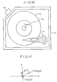
- FIG. 1 The construction and essential details of a conventional rotary actuator are shown in figures 1 and 2.
- three magnetic disks 112 are rotatably supported by a spindle 113 in a housing 111. These disks 112 are rotated at a constant speed, e.g. 3600 r.p.m. by a spindle motor 114.
- the magnetic heads 115 are held by head-supporting arms 117 through a suspension spring 116 and are positioned to the designated tracks of the magnetic disks 112 by the rotary actuator.
- the rotary actuator has a rotary member 118 which holds the head-supporting arms 117, and is rotatably journaled by the enclosure 111.
- the rotary actuator is driven by a positioning motor which may e.g. be a voice coil motor 119 that acts to rotate the rotating member 118 so as to displace the magnetic heads 115 by a specified angle about the rotational axis of the rotating member 118.
- the actuator is balanced between the head arm side and motor side such that its center of gravity passes through the rotational axis of the rotating member 118, to eliminate positioning errors that may occur as a result of vibrations acting along a translational direction.
- a closed loop servo is employed for controlling positioning of actuator.
- This closed loop servo determines an actual position of the magnetic head relative to an original point by reading servo information of the magnetic disk by means of the magnetic head. It then computes the distance the head has to move to reach the designated track position from the actual postion, and drives the positioning motor on the basis of the computed result, whereby the magnetic head is positioned onto the designated track.
- a prior art solution to the problem consists in making the servo gain large in order to reduce such positioning errors, but this approach has only a limited effect. Accordingly, it is generally attempted to act on the mechanical structure of the magnetic disk storage apparatus to attenuate the effects of external vibrations or impacts, by trying to obtain the largest possible attenuation ratio by installing vibration proofing rubber dampers between the enclosure 111 and frame.
- a conventional apparatus employs a structure having three or four vibration proofing rubber dampers of suitable spring constant disposed at the side or bottom plane of the enclosure to support the enclosure within the frame.
- Such a vibration proof structure has been effective within the practical range for large-size magnetic disk storage apparatus, but has become inadequate for the recent small-size and large-capacity magnetic disk storage apparatus.
- the track pitch is in this case very narrow to achieve the high recording density, and, moreover, the apparatus is prone to vibration or impact, being nowadays installed in small-size computers, such as lap top machines.
- the apparatus being lightweight, it tends to vibrate at large amplitudes even for small vibrations. Accordingly, the relative position of disk and head is easily deviated by vibrations acting in the translational direction, and head positioning errors are thus easily generated.
- the reference numerals denote as follows : 7, the center of the drive spindle for rotating a magnetic disk 1; 8, a track on which a magnetic head 2 is located; 9, the center of the rotating axis of the rotary actuator 3; 10′, the center of gravity when the enclosure is translated to the position indicated by a dotted line; 6, the frame; 5, 5′, the vibration proof supporting members.
- Figure 3(B) shows the displacements of the movable parts of the apparatus if the vibration proof supporting member 5′ were not provided to balance the primary moment around the center of gravity 10 of enclosure against external vibrations in the translational direction.
- the enclosure 4 makes a rotating movement around the center of gravity 10 and, consequently, the rotary actuator 3 moves from the position indicated by the solid line to the position indicated by the dotted line, as a result of the translational forces, so generating a large head positioning error ⁇ 0 .
- the vibration proof supporting member 5 balances the primary moment, around the center of gravity 10 of the enclosure arising from an external vibration acting in the translational direction.
- the enclosure only effects a translational movement.
- the center of gravity 10 of enclosure 4 moves to position 10′, and the track of magnetic disk 1 moves to the dotted line position from the parallel solid line, and almost no positioning error is generated.
- Figure 4 is a partly cut out schematic plan view of a magnetic disk storage apparatus according to a first embodiment.
- the reference numerals denote as follows : 11, the magnetic disk; 12, the magnetic head; 13, the head arm; 14, the enclosure; 15a, 15b, 15c, vibration proofing dampers serving as the vibration-attenuating suspension members; 16, the frame; 17, the center of the spindle; 18, a track of the disk; 19, the center of the rotation axis of the rotary actuator; and 20, the center of gravity of the enclosure.
- L1, L5 denote the distance from the center of gravity 20; and r pos′ the distance from the center of the rotating axis 19 of the actuator to the gap of the magnetic head 12.
- the enclosure 14 also comprises a disk driver, such as spindle motor (not illustrated).
- a disk driver such as spindle motor (not illustrated).
- three vibration proofing rubber dampers 15a to 15c are provided between the enclosure 14 and the frame 16.
- Vibration proofing rubber damper 15a has a spring constant ks along the X-direction and kc along the Y-direction. It is located at position L1 along the X-direction and at position L3 along the Y-direction relative to the center of gravity 20 of enclosure 14.
- Damper 15b has a spring constant kc along the X-direction and ks along the Y-direction, and is located at position L2 along the X-direction and L5 along the Y-direction relative to the center of gravity 20 of enclosure 14.
- Damper 15c has spring constants ks along the X-direction and kc along the Y-direction, and is located at position L1 along the X-direction and L4 along the Y-direction relative to the centre of gravity 20 of the enclosure 14.
- the distances L1, ... , L5 of the vibration proofing rubber dampers 15a, 15b, 15c relative to the center of gravity 20 of enclosure 14, and respective spring constants ks, kc of the dampers 15a, 15b, 15c are selected to satisfy the following two formulas.
- L1.kc + L1.kc - L2.ks 0
- L3.ks - L5.kc - L4.ks 0
- FIG. 5 is a detailed plan view of the first embodiment.
- the reference numerals are the same as in Figure 4.
- the three vibration proof dampers 15a, 15b, 15c have the spring constants kc in the compressing direction and ks in the shearing direction, and are held by the two metal plates. Their location between the enclosure 14 and frame 16 is determined as explained above, so that the linear moment around the center of gravity 20 of enclosure 14 is balanced. Therefore, as explained in regard to Figure 4, no rotational moment is generated within the enclosure 14 when external vibrations are present, and thus the positioning error ⁇ 0 is no longer generated.
- Each damoer 15a, 15b, 15c is fixed via metal receiving plates, for example, by fusing the rubber at the time of vulcanization or by using a bonding agent.
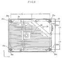
- Figure 6 is a plan view of a second embodiment of the present invention.
- the enclosure 24 is attached to fitting portions 26a, ..., 26d at the four corners of frame 26 through four vibration proofing dampers 25a, ..., 25d.
- Reference numeral 27 denotes the center of the spindle; 29, the center of rotation of the rotary actuator; and 30, the center of gravity of enclosure 24.
- Damper 25 has a spring constant ka along X and Y directions and is located at position L14 along the X-direction and at position L11 along the Y-direction relative to the center of gravity 30 of the enclosure 24.
- Damper 25b has a spring constant kb along X and Y directions and is located at position L13 along the X-direction and at position L11 along the Y-direction relative to the center of gravity 30 of the enclosure 24.
- Damper 25c has a spring constant kc along the X and Y directions and is located at position L13 along the X-direction and at position L12 along the Y-direction relative to the centre of gravity 30 of the enclosure 24.
- Damper 25d has a spring constant kd along the X and Y directions and is located at position L14 along the X-direction and at position L12 along the Y-direction relative to the center of gravity 30 of the enclosure 24.
- the enclosure 24 can be supported by the frame 26 in such a manner that no rotational moment M is transmitted to the enclosure 24 when external vibrations are present, and thus head positioning errors ⁇ 0 are effectively eliminated.
- the linear moment around the center of gravity 30 of the enclosure 24 can be balanced against external vibrations by an appropriate choice of spring constants ka, ..., kd of the dampers 25a, ..., 25d.
- the rotational movement of the enclosure can be suppressed by a simplified vibration proof mechanism consisting of a plurality of vibration proof rubbers.
- the vibration proof supporting member can consist not only of the aforementioned rubber dampers, but also of other attenuator elements. Moreover, it is also possible to reduce or increase a number of such elements. It is further possible, like in the following modification, to use different kinds of vibration proof supporting members.
- a vibration proof mechanism can be structured by a combination of vibration proofing dampers that have a different temperature behaviour as regards their damping characteristics.
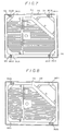
- FIG. 7 shows an embodiment in which a vibration proofing system is formed by bonding a rubber 311 element having good damping characteristics at the low end of the operating temperature range, to another rubber 312 element having good damping characteristics at the high temperature end of the scale, both elements 311 and 312 being bonded by a bonding agent to form a vibration proof rubber damper 31.
- the enclosure 24 is then supported by the frame 26 through such vibration proof rubber dampers.
- the enclosure 24 is supported with good damping characteristics by virtue of rubber element 311 and, when the ambient temperature rises to the higher end of the operating temperature range, the enclosure 24 is supported by the good damping characteristics of rubber element 312. Therefore, the vibration damping characteristics of the enclosure 24 can be improved for a wider temperature range. Moreover, an appropriate selection of thickness for each of the rubber elements 311, 312 equalizes the damping characteristics in each temperature within the operating temperature range.
- Figure 8 shows another variant of a vibration protection mechanism in which the enclosure 24 is supported by the frame 26 through a vibration proof rubber element 321 that has good damping characteristics at the low end of the operating temperature range, and a vibration proof rubberelement 322 that has good damping characteristics at the high end of the temperature range.
- the enclosure 24 is supported with good vibration damping characteristics of rubber element 321 at low temperatures within the operating temperature range, and with good vibration damping characteristics of rubber element 322 at high temperatures, the vibration characteristics of enclosure 24 are improved over a wide temperature range, as in the embodiment of Figure 7.
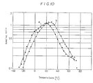
- Figure 9 and figure 10 respectively show temperature behaviour of the damping ratios of rubber elements made of different materials.
- Curve a of figure 9 shows the temperature characteristics of buthyl rubber. It can be seen that this material exhibits a maximum damping ratio loss factor at -20°C.
- Curve b shows the temperature characteristics of a thermoplastic resin, for example, SOFTOPER (registered trade name of Bridgestone), which exhibits a maximum damping ratio at +20°C.
- SOFTOPER registered trade name of Bridgestone
- the vibration damping characteristics of the enclosure 24 can be improved in the temperature range of -40°C to +40°C by using such materials for the rubber elements 311 (321), 312 (322) of the embodiments shown in figure 7 and figure 8.
- Curve a of figure 10 shows the temperature characteristics of the SOFTOPER thermoplastic resin, which exhibits the maximum damping ratio at 20°C
- curve b shows the temperature characteristic of another thermoplastic resin, for example, H-1 SOFTOPER (registered trade name of Bridgestone), which exhibits a maximum damping ratio at 30°C.
- the vibration characteristics of the enclosure 24 can be improved for the temperature range of 0°C to 40°C by using such materials for the rubber elements 311 (321), 312 (322) in the embodiments of figure 7 or figure 8.
- vibration damping rubber elements include, among others, ISODAMP (registered trade name of EAR) composed of a polymer compound material based on an elastomer agent, or SORBOSEIN (registered trade name) composed of ether polyurethane added with a reinforcing agent and a thermosetting agent to the base of polyole, and MDI. Some of these exhibit their optimum characteristics in the following ranges : 13 to 40°C, 27 to 55°C and 35 to 63°C, etc. . Therefore, it is also possible to combine three or more kinds of materials, each having different temperature characteristics, instead of combining just two, as in the embodiments of figure 7 or figure 8. The anti-vibration characteristics can then be further improved over a wider temperature range.
- ISODAMP registered trade name of EAR
- SORBOSEIN registered trade name
- the rigidity of the vibration proof supporting member must be set high (for a high resonance point of the vibration proof supporting system including the vibration proof supporting member) in order to suppress the self-rotaional movement of the enclosure by such a seek reaction force.
- This introduces a problem inasmuch as most of the external vibrations are then no longer attenuated, but transferred to the enclosure.
- the resonance frequency is set to the lower region, the relative vibration amplitude of the enclosure and frame becomes large for a seek reaction force or an external disturbance, and - in the worse case - the enclosure makes contact with the frame.
- the distance between the enclosure and frame is set large, there is a problem in that the apparatus becomes large in size.
- the vibration proof effect can be improved by suitably setting the relationship between the servo bandwidth of the servo control system controlling the rotary actuator and the resonance frequency of the supporting system, including the vibration damping supporting members.
- the resonance frequency of the supporting system is at least set to be the outside of range 1/5 to 1/4 of the servo bandwidth.
- the servo bandwidth means the frequency at which the open loop gain becomes 0 dB.
- Figure 11 is a schematic diagram showing the mutual relationship between the disk rotating system, head postioning system, servo control system and enclosure supporting system.
- the reference numerals denote as follows : 41, a magnetic disk; 42, a servo head; 43, a data head; 44, a rotary actuator consisting of voice coil motor; 45, the enclosure; 46, the vibration proof supporting member; 47, the frame; 48, a spindle motor; 49, 50 an amplifier; 51, a demodulator for demodulaing a servo signal; 52, an A/D converter; 53, a D/A converter; 54, a read/write control circuit; 55, a motor control circuit, 56, a main controller consisting of a microprocessor, etc.
- the above electric circuits are indicated as being provided within the enclosure, but in practice the greater part of them would actually be located outside the enclosure.
- the servo control system is formed by the closed loop comprising the servo head 42 - amplifiers 49 - demodulator 51 - A/D converter 52 - main controller 56 - D/A converter 53 - amplifier 50 - rotary actuator 44.
- the functions of this servo control system being already known, they will not be explained here in further detail.
- the vibration proof supporting member 46 can be simulated by an equivalent circuit including spring constants and attenuation constants.
- the supporting system including the above vibration proof supporting member 46 has a resonance frequency f sus . Since this resonance frequency (resonance point of the supporting system) involves the rotary actuator 44, the rotating resonance point becomes a problem.
- Figure 12 is a diagram for explaining the relative displacement between disk 41 and head 64 due to vibrations in the enclosure generated by the seek reaction force.
- the enclosure 45 is vibrated as indicated by the arrow mark, because of the rotating moment M due to the seek reaction force.
- Such vibration imparts a rotating movement to the enclosure 45 that is similar to the consequences of the external translational vibrations. Therefore, when the positioning control is not conducted by the servo control system, the magnetic disk 41 is displaced, together with the enclosure, from the solid line position to the dotted line position, around the center of gravity 61, and the head arm 62 is only translated due to the displacements of the center of rotation 63.
- the magnetic head 64 ( 42, 43) and the track 411 of the magnetic disk 41 are displaced relative to each other in the radial direction only by the distance ⁇ 0 .
- relative displacement ⁇ 0 can be eliminated. This relative displacement ⁇ 0 corresponds to the potential positioning error.
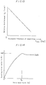
- the resonance frequency of the supporting system and the relative displacement shown in figure 13 are in a linear relation when the resonance frequency of the supporting system f sus [Hz] is plotted on the horizontal axis (logarithmic scale), while relative displacement ⁇ 0 [ m] is plotted on the vertical axis (dB scale).
- This result means that when the vibration proof supporting member 46 is made of a comparatively hard rubber, in order to set the resonance frequency of supporting system f sus to a higher region of the scale, vibration amplitude becomes smaller, and relative displacement ⁇ 0 becomes small.
- the vibration proof supporting member 15 is formed by a comparatively soft rubber, in order to set the resonance frequency of supporting system f sus to a higher region of the scale, vibration amplitude becomes large and the relative displacement ⁇ 0 also becomes large.
- FIG. 14 An example of the relationship between the servo bandwidth of servo control system (including the rotary actuator 44) and tracking error rate of servo control system is shown in figure 14. It can be seen that when the servo bandwidth [Hz] is plotted on the horizontal axis (logarithmic scale) and the tracking error rate [dB] is plotted on the vertical axis, the servo bandwidth extends up to the maximum gain MP, which results in the minimum tracking error rate.
- the vibration-induced rotation angle of the enclosure will be highest (worst case) when the rotation vibration frequency f s matches the resonance frequency f sus of supporting system.
- This condition is determined, together with the relative displacement ⁇ 0 in the current track position of the magnetic head 64 (42, 43), from the geometrical conditions using a curve as shown in figure 13. Therefore, a product of relative displacement ⁇ 0 and tracking error ratio is plotted with the resonance frequency f sus [Hz] of the supporting system on the horizontal axis (logarithmic scale).
- the positioning error [%] is normalized with the maximum positional deviation for reading or writing information (offset margin : 10 to 15% of the ordinary track pitch).
- the related curve shown in figure 15 can be obtained.
- the maximum value of the positioning error is generated in the range of 1/4 to 1/5 of the servo bandwidth f 0 .
- the peak of the positioning error shifts to the right side.
- the resonance frequency f sus of the supporting system (including the vibration proof supporting member 46) is set outside the range of 1/5 to 1/4 of the servo bandwidth f 0 .
- the allowable positioning error for vibration discussed here is about 40% for the offset margin. This condition can thus be satisfied by setting f sus to a range lower than f 0 /10 or higher than f 0 . Accordingly, the necessary positioning accuracy can be attained without excessively lowering the resonance factor of supporting system.
- the frequency f sus can be made higher than f 0 .
- the vibration damping can be improved for vibration resulting from external forces and seek reaction force without excessively lowering the resonance frequency of the supporting system, including the vibration proof supporting member.
- the distance between the enclosure and frame can be narrowed, and accordingly, the apparatus itself can be reduced in size.
- a high rotational speed for the disk is essential for rapid data transfer. Consequently, even if there exists only a slight amount of unbalance in rotation of the disk and spindle in such a high speed disk apparatus, vibration of the enclosure will become a problem, generating the rotational movement component in the enclosure.
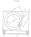
- the second embodiment of the present invention suppresses such rotational movement of enclosure, arising from unbalance in rotation of disk rotating system, by matching of the center of gravity 73 of the enclosure 71 with the center of rotation 76 of the spindle 75. To this end, a weight 72 is attached to the enclosure as shown in figure 16.
- the resulting torque T, at the axis passing the center of gravity 73 and in a direction parallel to the axis of spindle 75 are applied to the center of gravity 73 (0, 0) of the enclosure 71, along with the translational forces F x , F y .
- center of gravity 73 describes a circular motion with angular velocity ⁇ and radius ⁇ /m and also makes a rotational movement with the swing angle of 2 ⁇ l/J.
- This distance l can easily be set to zero in the design stage.
- the center of gravity 73 of the enclosure 71 is made to coincide with the center of rotation 76 of the spindle 75 by adding a weight 72 thereto.
- this embodiment provides the advantage of small size, large capacity and high speed magnetic disk storage capacity in an apparatus at a remarkably reduced cost. Therefore, in combination with the first embodiment, a vibration free structure having excellent performance and economical advantage can be obtained. It is of course possible to solely utilize this expansion.
- a vibration proof structure having a double frame and a plurality of vibration proof supporting members located between the frames and between the enclosure and the frame.
- Figure 18 shows a plan view of a magnetic disk storage apparatus conforming to such a variant.
- an intermediate frame 83 is provided between the enclosure 81 and external frame 82.
- the four vibration proof dampers 84 to 87 are provided at the four corners in the interval between the external frame 82 and the intermediate frame 83.
- Four vibration proof dampers 88 to 91 are also provided between the intermediate frame 83 and enclosure 81.
- the two pairs of vibration proof dampers are made of rubber. They are flexible in the shearing direction and hard in the compression direction.
- the enclosure 81 is flexiby supported in the X-direction for the intermediate frame 83 and in the Y-direction for the external frame 82. Moreover, the enclosure 81 is supported very rigidly in the rotating direction. Therefore, the rotational movement of the enclosure can be made to suppress vibrations arising from a seek reaction force, as well as those arising from external translational vibrations. As a result, relative displacement between the head and disk can be prevented.
Landscapes
- Moving Of Heads (AREA)
Claims (12)
- Appareil de stockage à disque magnétique comportant, dans une enceinte (14; 24; 81), au moins un disque magnétique (1; 11) devant être entraîné en rotation par un mécanisme d'entraînement en rotation et un dispositif d'actionnement rotatif (13; 43) destiné à positionner une tête magnétique (2; 64) sur une piste désignée (18; 411) dudit disque par un déplacement relatif; etun châssis (6; 16; 26) destiné à recevoir ladite enceinte etplusieurs éléments de support anti-vibration (5a, ... 5d; 15a, ... 15d; 25a, ... 25d; 311, 312; 321, 322) prévus entre ledit châssis et ladite enceinte;caractérisé en ce que lesdits éléments de support anti-vibration (5a, ... 5d; 15a, ... 15d; 25a, ... 25d; 311, 312; 321, 322) comportent plusieurs éléments élastiques qui sont décalés par rapport aux axes principaux X, Y passant par le centre de gravité de l'enceinte sur des distances prédéterminées respectives et qui ont des constantes prédéterminées de cisaillement et de ressort en compression de façon à satisfaire la relation :
 où le centre de gravité se trouve à l'origine (0,0), la coordonnée (Xi, Yi) indique la position du ième élément de support anti-vibration, et chacun des Kxi, Kyi désigne respectivement la constante de ressort dans les directions Y et Y,le mouvement linéaire autour du centre de gravité de ladite enceinte étant équilibré à l'encontre de l'entrée de vibration en translation dans le plan perpendiculaire à l'axe de rotation dudit disque, appliquée par l'intermédiaire dudit châssis.
 - Appareil de stockage à disque magnétique selon la revendication 1, caractérisé en ce qu'il comporte en outre un système de servocommande du type à boucle fermée destiné à commander le positionnement dudit dispositif d'actionnement rotatif (43), la fréquence de résonance du système de support comprenant ledit élément de support anti-vibration qui est disposé de façon à s'étendre en dehors d'une plage d'au moins 1/5 à 1/4 de la bande passante d'asservissement dudit système de servocommande.
- Appareil de stockage à disque magnétique selon la revendication 1, caractérisé en ce que le centre de rotation d'une broche (7; 17; 27) supportant le centre dudit disque magnétique coïncide avec le centre de gravité de ladite enceinte.
- Appareil de stockage à disque magnétique comportant :(a) au moins un disque magnétique (1; 11) destiné à stocker des données;(b) un mécanisme d'entraînement en rotation (48) destiné à faire tourner ledit disque magnétique; (c) des têtes magnétiques (2; 12; 22) destinées à écrire ou lire des données sur la piste désignée (18; 411) dudit disque;(d) un dispositif d'actionnement rotatif (13; 43) destiné à positionner ladite tête sur la piste désignée dudit disque grâce à un déplacement relatif, ledit dispositif d'actionnement supportant ladite tête, et formant une partie mobile qui peut tourner sur un angle déterminé autour du centre de rotation et ayant un centre de gravité qui coïncide avec l'axe de centre de rotation;(e) des moyens de servocommande du type à boucle fermée destinés à commander le positionnement dudit dispositif d'actionnement rotatif;(f) une enceinte (14; 24; 81) recevant lesdits éléments dans une relation de position prédéterminée de sorte que le centre de gravité de celle-ci coïncide avec l'axe de rotation dudit disque;(g) un châssis (6; 16; 26) destiné à recevoir ladite enceinte; et(h) plusieurs éléments de support anti-vibration (5a, ... 5d; 15a, ... 15d; 25a, ... 25d; 311, 312; 321, 322) destinés à supporter ladite enceinte avec ledit châssis,caractérisé en ce que lesdits éléments de support anti-vibration (5a, ... 5d; 15a, ... 15d; 25a, ... 25d; 311, 312; 321, 322) comportent plusieurs éléments élastiques qui sont décalés par rapport aux axes principaux X, Y passant par le centre de gravité de l'enceinte sur des distances prédéterminées respectives et qui ont des constantes prédéterminées de cisaillement et de ressort en compression de façon à satisfaire la relation :
 où le centre de gravité se trouve à l'origine (0,0), la coordonnée (Xi, Yi) indique la position du ième élément de support anti-vibration, et chacun des KXi, KYi désigne respectivement la constante de ressort dans les directions Y et Y,le mouvement linéaire autour du centre de gravité de ladite enceinte étant équilibré à l'encontre de l'entrée de vibration en translation dans le plan perpendiculaire à l'axe de rotation dudit disque, appliquée par l'intermédiaire dudit châssis,et en ce que la fréquence de résonance du système de support comprenant les éléments de support anti-vibration, est déterminée de façon à s'étendre en dehors d'une plage d'au moins 1/5 à 1/4 de bande passante d'asservissement dudit système de servocommande.
 - Appareil de stockage à disque magnétique selon les revendications 1, 2, 3 ou 4, caractérisé en ce que ledit élément de support anti-vibration (5a, ... 5d; 15a, ... 15d; 25a, ... 25d; 311, 312; 321, 322) est formé par une matière élastique.
- Appareil de stockage à disque magnétique selon la revendication 2 ou 4, caractérisé en ce que la fréquence de résonance du système de support, comprenant lesdits éléments de support anti-vibration, est déterminée pour être de 1/10 ou moins de la bande passante d'asservissement du système de servocommande.
- Appareil de stockage à disque magnétique selon la revendication 2 ou 4, caractérisé en ce que la fréquence de résonance du système de support comprenant lesdits éléments de support anti-vibration (5a, ... 5d; 15a, ... 15d; 25a, ... 25d; 311, 312; 321, 322) est déterminée pour être plus grande que la bande passante d'asservissement du système de servocommande.
- Appareil de stockage à disque magnétique selon la revendication 5, caractérisé en ce que chaque élément de support anti-vibration (5a, ... 5d; 15a, ... 15d; 25a, ... 25d; 311, 312; 321, 322) est formé en caoutchouc anti-vibration.
- Appareil de stockage à disque magnétique selon la revendication 8, caractérisé en ce que plusieurs paires d'éléments de support anti-vibration (311, 312; 321, 322) sont prévues, et chaque élément de support anti-vibration de chaque paire est formé en caoutchouc anti-vibration ayant des comportements en température différents sur le plan de leurs caractéristiques d'amortissement.
- Appareil de stockage à disque magnétique selon la revendication 8, caractérisé en ce que chaque élément de support anti-vibration relie plusieurs matières en caoutchouc ayant des comportements en température différents sur le plan de leur caractéristique d'amortissement.
- Appareil de stockage à disque magnétique selon la revendication 1, caractérisé en ce que ledit châssis (82, 83) se compose d'une construction double ayant un châssis extérieur (82) et un châssis intérieur (83) qui sont supportés mutuellement par plusieurs éléments de support anti-vibration (84, ... 87).
- Appareil de stockage à disque magnétique selon la revendication 11, caractérisé en ce que ladite enceinte (81) est supportée sur ledit châssis intérieur (83) par plusieurs premiers éléments de support anti-vibration (88, ... 90) qui sont rigides dans une première direction et flexibles dans une deuxième direction, perpendiculaires à ladite première direction, et en ce que ledit châssis interne est supporté par ledit châssis extérieur (82) par plusieurs deuxièmes éléments de support anti-vibration (84, ... 87) qui sont flexibles dans ladite première direction et rigides dans ladite deuxième direction.
Applications Claiming Priority (8)
| Application Number | Priority Date | Filing Date | Title |
|---|---|---|---|
| JP240198/89 | 1989-09-18 | ||
| JP1240198A JP2777917B2 (ja) | 1989-09-18 | 1989-09-18 | 磁気ディスク装置 |
| JP270450/89 | 1989-10-19 | ||
| JP27045089A JP2754413B2 (ja) | 1989-10-19 | 1989-10-19 | 磁気ディスク装置 |
| JP37196/90 | 1990-02-20 | ||
| JP2037196A JP2777922B2 (ja) | 1990-02-20 | 1990-02-20 | 磁気ディスク装置 |
| JP5642290A JP2725071B2 (ja) | 1990-03-09 | 1990-03-09 | 磁気ディスク装置 |
| JP56422/90 | 1990-03-09 |
Publications (3)
| Publication Number | Publication Date |
|---|---|
| EP0419345A2 EP0419345A2 (fr) | 1991-03-27 |
| EP0419345A3 EP0419345A3 (en) | 1992-11-25 |
| EP0419345B1 true EP0419345B1 (fr) | 1996-12-27 |
Family
ID=27460375
Family Applications (1)
| Application Number | Title | Priority Date | Filing Date |
|---|---|---|---|
| EP90402573A Expired - Lifetime EP0419345B1 (fr) | 1989-09-18 | 1990-09-18 | Appareil à disque magnétique avec une résistance améliorée aux vibrations |
Country Status (5)
| Country | Link |
|---|---|
| US (1) | US5349486A (fr) |
| EP (1) | EP0419345B1 (fr) |
| KR (1) | KR950001611B1 (fr) |
| CA (1) | CA2025497C (fr) |
| DE (1) | DE69029496T2 (fr) |
Families Citing this family (82)
| Publication number | Priority date | Publication date | Assignee | Title |
|---|---|---|---|---|
| US5875067A (en) * | 1991-03-22 | 1999-02-23 | Seagate Technology, Inc. | Acoustic isolator for a disc drive assembly |
| JP3087809B2 (ja) * | 1994-01-14 | 2000-09-11 | 富士通株式会社 | ディスク装置のフレーム取付構造 |
| US5798885A (en) * | 1994-06-06 | 1998-08-25 | Fujitsu Limited | Head positioning control for disk apparatus using peak detection, polarity detection and sector mark detection |
| JP2594760B2 (ja) * | 1994-07-20 | 1997-03-26 | 茨城日本電気株式会社 | 磁気ディスク装置の衝撃緩衝装置 |
| US6567265B1 (en) | 1995-11-20 | 2003-05-20 | Matsushita Electric Industrial Co., Ltd. | Apparatus having flexible mounting mechanism |
| JP3195213B2 (ja) * | 1995-12-18 | 2001-08-06 | 株式会社日立製作所 | 回転形情報記録再生装置 |
| JPH1031854A (ja) * | 1996-07-18 | 1998-02-03 | Mitsumi Electric Co Ltd | ディスク装置 |
| US5654875A (en) * | 1996-07-26 | 1997-08-05 | Ibm | Isolator mounting system for small form factor hard disk drive |
| JPH10222972A (ja) * | 1997-02-05 | 1998-08-21 | Matsushita Electric Ind Co Ltd | 記憶装置、及びそれに用いる耐衝撃用収納容器 |
| JP3746355B2 (ja) * | 1997-03-19 | 2006-02-15 | 富士通株式会社 | ディスク装置 |
| JP2001502103A (ja) * | 1997-07-31 | 2001-02-13 | 富士通株式会社 | 携帯型コンピュータのハードディスクドライブ装置用緩衝取付 |
| US6108174A (en) * | 1997-08-15 | 2000-08-22 | Seagate Technology, Inc. | Tuning actuator arm displacement characteristics to reduce damage from mechanical shocks |
| US6018437A (en) * | 1997-10-16 | 2000-01-25 | Seagate Technology, Inc. | Disc drive servo writer support assembly |
| JP4105309B2 (ja) | 1997-11-06 | 2008-06-25 | 富士通株式会社 | 電子装置及び搭載機構 |
| US6785217B1 (en) * | 1998-01-27 | 2004-08-31 | Wistron Corporation | Method and device for reducing vibration of a high speed disk drive |
| JP4335328B2 (ja) * | 1998-02-13 | 2009-09-30 | 富士通株式会社 | 記録ディスク装置用ハウジングおよび記録ディスク装置 |
| US6381091B1 (en) * | 1998-07-23 | 2002-04-30 | Matsushita Electric Industrial Co., Ltd. | Disk drive apparatus |
| US6097608A (en) * | 1998-11-16 | 2000-08-01 | International Business Machines Corporation | Disk drive vibration isolation using diaphragm isolators |
| EP1163570A4 (fr) | 1999-02-19 | 2007-12-19 | Gen Dynamics Inf Systems Inc | Boitier de stockage de donnees |
| JP3713404B2 (ja) * | 1999-06-21 | 2005-11-09 | アルプス電気株式会社 | 磁気ディスク駆動装置 |
| IL132732A0 (en) * | 1999-11-03 | 2001-03-19 | Bar Lev Noam | Isolating system |
| US6477042B1 (en) * | 1999-11-18 | 2002-11-05 | Siemens Energy & Automation, Inc. | Disk drive mounting system for absorbing shock and vibration in a machining environment |
| US6683745B1 (en) | 1999-12-27 | 2004-01-27 | Hitachi Global Storage Technologies Netherlands B.V. | Rotationally free mount system for disk drive having a rotary actuator |
| US6671124B2 (en) * | 2001-09-07 | 2003-12-30 | Lockheed Martin Corporation | Shock and vibration system |
| JP2003272371A (ja) * | 2002-03-14 | 2003-09-26 | Sony Corp | 情報記憶装置 |
| US20040064631A1 (en) * | 2002-06-03 | 2004-04-01 | Viewsonic Corporation | Pixel vault |
| US7178794B2 (en) * | 2002-09-10 | 2007-02-20 | Seagate Technology Llc | Fluid isolator assembly and floating elastomeric damping element |
| JP2004127414A (ja) * | 2002-10-02 | 2004-04-22 | Shinano Kenshi Co Ltd | ディスク装置 |
| JP3861791B2 (ja) * | 2002-10-11 | 2006-12-20 | ソニー株式会社 | 緩衝材及びこれを用いた情報記憶装置 |
| CN100470663C (zh) * | 2003-03-31 | 2009-03-18 | 松下电器产业株式会社 | 冲击缓冲部件、冲击缓冲方法以及使用它们的电子机器 |
| KR100594285B1 (ko) * | 2004-07-03 | 2006-06-30 | 삼성전자주식회사 | 오픈-셀 구조를 가진 완충 부재를 채용한 하드 디스크드라이브의 하우징 |
| US7259966B2 (en) * | 2004-08-31 | 2007-08-21 | International Business Machines Corporation | Apparatus, system, and method for reducing rotational vibration transmission within a data storage system |
| KR20070121699A (ko) * | 2005-03-23 | 2007-12-27 | 지라텍스 테크놀로지 리미티드 | 디스크 드라이브 지지용 장치 및 디스크 드라이브 테스트장치 |
| TWI288594B (en) * | 2005-05-09 | 2007-10-11 | Benq Corp | Anti-shock mechanism |
| KR100772690B1 (ko) * | 2005-07-18 | 2007-11-02 | 삼성전자주식회사 | 디스크 드라이브의 완충기 및 이를 포함한 디스크 드라이브어셈블리 |
| US20080112125A1 (en) * | 2006-11-09 | 2008-05-15 | Imation Corp. | Portable hard drive with axis specific shock absorption |
| US7701705B1 (en) | 2007-12-10 | 2010-04-20 | Western Digital Technologies, Inc. | Information storage device with sheet metal projections and elastomeric inserts |
| US8164849B1 (en) | 2007-12-10 | 2012-04-24 | Western Digital Technologies, Inc. | Information storage device with a conductive shield having free and forced heat convection configurations |
| US8549912B2 (en) | 2007-12-18 | 2013-10-08 | Teradyne, Inc. | Disk drive transport, clamping and testing |
| US7996174B2 (en) | 2007-12-18 | 2011-08-09 | Teradyne, Inc. | Disk drive testing |
| US8004791B2 (en) * | 2008-02-22 | 2011-08-23 | Western Digital Technologies, Inc. | Information storage device with a bridge controller and a plurality of electrically coupled conductive shields |
| US8390952B1 (en) | 2008-02-22 | 2013-03-05 | Western Digital Technologies, Inc. | Information storage device having a conductive shield with a peripheral capacitive flange |
| US8160739B2 (en) | 2008-04-17 | 2012-04-17 | Teradyne, Inc. | Transferring storage devices within storage device testing systems |
| US8041449B2 (en) | 2008-04-17 | 2011-10-18 | Teradyne, Inc. | Bulk feeding disk drives to disk drive testing systems |
| US8305751B2 (en) | 2008-04-17 | 2012-11-06 | Teradyne, Inc. | Vibration isolation within disk drive testing systems |
| US7848106B2 (en) | 2008-04-17 | 2010-12-07 | Teradyne, Inc. | Temperature control within disk drive testing systems |
| US20090262455A1 (en) | 2008-04-17 | 2009-10-22 | Teradyne, Inc. | Temperature Control Within Disk Drive Testing Systems |
| US8117480B2 (en) | 2008-04-17 | 2012-02-14 | Teradyne, Inc. | Dependent temperature control within disk drive testing systems |
| US8102173B2 (en) | 2008-04-17 | 2012-01-24 | Teradyne, Inc. | Thermal control system for test slot of test rack for disk drive testing system with thermoelectric device and a cooling conduit |
| US8238099B2 (en) | 2008-04-17 | 2012-08-07 | Teradyne, Inc. | Enclosed operating area for disk drive testing systems |
| US8095234B2 (en) | 2008-04-17 | 2012-01-10 | Teradyne, Inc. | Transferring disk drives within disk drive testing systems |
| US7945424B2 (en) | 2008-04-17 | 2011-05-17 | Teradyne, Inc. | Disk drive emulator and method of use thereof |
| JP2011524060A (ja) | 2008-06-03 | 2011-08-25 | テラダイン、 インコーポレイテッド | 記憶デバイスを処理する方法 |
| US8300352B1 (en) | 2009-06-18 | 2012-10-30 | Western Digital Technologies, Inc. | Disk drive having mounting inserts with cantilevered beams |
| US8466699B2 (en) | 2009-07-15 | 2013-06-18 | Teradyne, Inc. | Heating storage devices in a testing system |
| US8116079B2 (en) | 2009-07-15 | 2012-02-14 | Teradyne, Inc. | Storage device testing system cooling |
| US8687356B2 (en) | 2010-02-02 | 2014-04-01 | Teradyne, Inc. | Storage device testing system cooling |
| US7920380B2 (en) | 2009-07-15 | 2011-04-05 | Teradyne, Inc. | Test slot cooling system for a storage device testing system |
| US8547123B2 (en) | 2009-07-15 | 2013-10-01 | Teradyne, Inc. | Storage device testing system with a conductive heating assembly |
| US7995349B2 (en) | 2009-07-15 | 2011-08-09 | Teradyne, Inc. | Storage device temperature sensing |
| US8628239B2 (en) | 2009-07-15 | 2014-01-14 | Teradyne, Inc. | Storage device temperature sensing |
| US9779780B2 (en) | 2010-06-17 | 2017-10-03 | Teradyne, Inc. | Damping vibrations within storage device testing systems |
| US8687349B2 (en) | 2010-07-21 | 2014-04-01 | Teradyne, Inc. | Bulk transfer of storage devices using manual loading |
| US9001456B2 (en) | 2010-08-31 | 2015-04-07 | Teradyne, Inc. | Engaging test slots |
| US8705201B2 (en) | 2011-12-20 | 2014-04-22 | Western Digital Technologies, Inc. | Information storage device with a damping insert sheet between a housing bay and a disk drive |
| US8462460B1 (en) | 2012-03-29 | 2013-06-11 | Western Digital Technologies, Inc. | Shock mount and retainer for a disk drive enclosure |
| US8547658B1 (en) | 2012-10-18 | 2013-10-01 | Western Digital Technologies, Inc. | Data storage device enclosure enabling use of a common shock mount across different products |
| US9459312B2 (en) | 2013-04-10 | 2016-10-04 | Teradyne, Inc. | Electronic assembly test system |
| US9360900B1 (en) | 2013-08-21 | 2016-06-07 | Western Digital Technologies, Inc. | Captivating shock mounts for data storage devices using retention clips |
| US9361947B1 (en) * | 2015-06-10 | 2016-06-07 | Western Digital Technologies, Inc. | Hard disk drive motor cup support |
| US10845410B2 (en) | 2017-08-28 | 2020-11-24 | Teradyne, Inc. | Automated test system having orthogonal robots |
| US10948534B2 (en) | 2017-08-28 | 2021-03-16 | Teradyne, Inc. | Automated test system employing robotics |
| US10725091B2 (en) | 2017-08-28 | 2020-07-28 | Teradyne, Inc. | Automated test system having multiple stages |
| US11226390B2 (en) | 2017-08-28 | 2022-01-18 | Teradyne, Inc. | Calibration process for an automated test system |
| US10983145B2 (en) | 2018-04-24 | 2021-04-20 | Teradyne, Inc. | System for testing devices inside of carriers |
| US10775408B2 (en) | 2018-08-20 | 2020-09-15 | Teradyne, Inc. | System for testing devices inside of carriers |
| US11754596B2 (en) | 2020-10-22 | 2023-09-12 | Teradyne, Inc. | Test site configuration in an automated test system |
| US11754622B2 (en) | 2020-10-22 | 2023-09-12 | Teradyne, Inc. | Thermal control system for an automated test system |
| US11867749B2 (en) | 2020-10-22 | 2024-01-09 | Teradyne, Inc. | Vision system for an automated test system |
| US11899042B2 (en) | 2020-10-22 | 2024-02-13 | Teradyne, Inc. | Automated test system |
| US11953519B2 (en) | 2020-10-22 | 2024-04-09 | Teradyne, Inc. | Modular automated test system |
| US12007411B2 (en) | 2021-06-22 | 2024-06-11 | Teradyne, Inc. | Test socket having an automated lid |
Family Cites Families (12)
| Publication number | Priority date | Publication date | Assignee | Title |
|---|---|---|---|---|
| US3484760A (en) * | 1966-06-09 | 1969-12-16 | Control Data Corp | Disc file and actuator therefor |
| US3886595A (en) * | 1974-02-13 | 1975-05-27 | Information Storage Systems | Actuator for a disc drive apparatus |
| US4263629A (en) * | 1977-09-30 | 1981-04-21 | International Business Machines Corporation | Disk file with symmetrical hollow base |
| US4642715A (en) * | 1984-11-01 | 1987-02-10 | Miltope Corporation | Environmental conditioning and safety system for disk-type mass memories |
| JPS61162884A (ja) * | 1985-01-14 | 1986-07-23 | Matsushita Electric Ind Co Ltd | 再生装置等の防振装置 |
| US4703470A (en) * | 1985-08-15 | 1987-10-27 | Priam (Delaware) Corporation | Dynamic absorber device for use with disk drives |
| JPS6292197A (ja) * | 1985-10-18 | 1987-04-27 | Hitachi Ltd | 磁気デイスク装置 |
| US4713714A (en) * | 1985-11-26 | 1987-12-15 | Motorola Computer Systems, Inc. | Computer peripheral shock mount for limiting motion-induced errors |
| JP2718665B2 (ja) * | 1986-07-09 | 1998-02-25 | 株式会社日立製作所 | フアイル記憶装置 |
| US4933785A (en) * | 1988-03-01 | 1990-06-12 | Prairietek Corporation | Disk drive apparatus using dynamic loading/unloading |
| US4893210A (en) * | 1988-07-11 | 1990-01-09 | Danford Corporation | Computer disk drive assembly having a resiliently supported separable disk pack unit |
| US4999724A (en) * | 1989-11-13 | 1991-03-12 | Hewlett-Packard Company | Disk drive having an electrically isolated disk stack |
-
1990
- 1990-09-17 CA CA002025497A patent/CA2025497C/fr not_active Expired - Fee Related
- 1990-09-18 DE DE69029496T patent/DE69029496T2/de not_active Expired - Fee Related
- 1990-09-18 KR KR1019900014699A patent/KR950001611B1/ko not_active Expired - Fee Related
- 1990-09-18 EP EP90402573A patent/EP0419345B1/fr not_active Expired - Lifetime
-
1992
- 1992-09-29 US US07/954,951 patent/US5349486A/en not_active Expired - Fee Related
Also Published As
| Publication number | Publication date |
|---|---|
| KR950001611B1 (ko) | 1995-02-27 |
| CA2025497A1 (fr) | 1991-03-19 |
| EP0419345A2 (fr) | 1991-03-27 |
| DE69029496D1 (de) | 1997-02-06 |
| US5349486A (en) | 1994-09-20 |
| CA2025497C (fr) | 1996-05-28 |
| DE69029496T2 (de) | 1997-04-10 |
| EP0419345A3 (en) | 1992-11-25 |
| KR910006966A (ko) | 1991-04-30 |
Similar Documents
| Publication | Publication Date | Title |
|---|---|---|
| EP0419345A2 (fr) | Appareil à disque magnétique avec une résistance améliorée aux vibrations | |
| US4812932A (en) | Vibration proof supporting structure for disk-type information memory unit | |
| US5124855A (en) | Disk file with isolation mount | |
| US6674600B1 (en) | Disk drive having separate motion sensors for base and actuator | |
| KR100491402B1 (ko) | 디스크 저장 시스템 및 헤드/디스크 조립체용 장착 시스템 | |
| EP0341957B1 (fr) | Structure d'absorption de vibration d'un appareil à disque | |
| US5371636A (en) | Mechanisms for a closed loop head positioner for streaming tape drives | |
| US5764441A (en) | Head actuator having reduced and controlled vibration characteristics for high speed disk drive systems | |
| US6259671B1 (en) | Object lens actuator | |
| US7230798B2 (en) | Head support device and disk drive using the same | |
| JPS6025073A (ja) | 浮動ヘツド支持装置 | |
| JPS59210572A (ja) | バンド駆動アクチユエ−タ−を有するデイスク駆動装置の機械的ダンパ− | |
| US4855851A (en) | Head suspension for magnetic recording | |
| CN101490763A (zh) | 盘装置 | |
| JPH0471257B2 (fr) | ||
| EP0246375B1 (fr) | Assemblage tête/bras et mécanisme d'accès rotatif pour mémoire à disques | |
| JP2754413B2 (ja) | 磁気ディスク装置 | |
| JP2777917B2 (ja) | 磁気ディスク装置 | |
| JPS6010384B2 (ja) | 磁気ヘツド駆動用アクチユエ−タ | |
| JPH07122017A (ja) | ハードディスク装置用の磁気ヘッド支持機構 | |
| JPH04103089A (ja) | ディスクファイル装置 | |
| JPH0449583A (ja) | トランスデューサ支持装置 | |
| JP3895137B2 (ja) | 磁気ディスク装置 | |
| JPS59132458A (ja) | フレキシプル・デイスク・ドライブのヘツド支持構造 | |
| JPS6010466A (ja) | 磁気デイスク装置 |
Legal Events
| Date | Code | Title | Description |
|---|---|---|---|
| PUAI | Public reference made under article 153(3) epc to a published international application that has entered the european phase |
Free format text: ORIGINAL CODE: 0009012 |
|
| AK | Designated contracting states |
Kind code of ref document: A2 Designated state(s): DE FR GB IT |
|
| PUAL | Search report despatched |
Free format text: ORIGINAL CODE: 0009013 |
|
| AK | Designated contracting states |
Kind code of ref document: A3 Designated state(s): DE FR GB IT |
|
| 17P | Request for examination filed |
Effective date: 19921221 |
|
| 17Q | First examination report despatched |
Effective date: 19940301 |
|
| GRAH | Despatch of communication of intention to grant a patent |
Free format text: ORIGINAL CODE: EPIDOS IGRA |
|
| GRAH | Despatch of communication of intention to grant a patent |
Free format text: ORIGINAL CODE: EPIDOS IGRA |
|
| GRAA | (expected) grant |
Free format text: ORIGINAL CODE: 0009210 |
|
| AK | Designated contracting states |
Kind code of ref document: B1 Designated state(s): DE FR GB IT |
|
| PG25 | Lapsed in a contracting state [announced via postgrant information from national office to epo] |
Ref country code: IT Free format text: LAPSE BECAUSE OF FAILURE TO SUBMIT A TRANSLATION OF THE DESCRIPTION OR TO PAY THE FEE WITHIN THE PRE;WARNING: LAPSES OF ITALIAN PATENTS WITH EFFECTIVE DATE BEFORE 2007 MAY HAVE OCCURRED AT ANY TIME BEFORE 2007. THE CORRECT EFFECTIVE DATE MAY BE DIFFERENT FROM THE ONE RECORDED.SCRIBED TIME-LIMIT Effective date: 19961227 Ref country code: FR Effective date: 19961227 |
|
| REF | Corresponds to: |
Ref document number: 69029496 Country of ref document: DE Date of ref document: 19970206 |
|
| EN | Fr: translation not filed | ||
| PG25 | Lapsed in a contracting state [announced via postgrant information from national office to epo] |
Ref country code: GB Free format text: LAPSE BECAUSE OF NON-PAYMENT OF DUE FEES Effective date: 19970918 |
|
| PLBE | No opposition filed within time limit |
Free format text: ORIGINAL CODE: 0009261 |
|
| STAA | Information on the status of an ep patent application or granted ep patent |
Free format text: STATUS: NO OPPOSITION FILED WITHIN TIME LIMIT |
|
| 26N | No opposition filed | ||
| GBPC | Gb: european patent ceased through non-payment of renewal fee |
Effective date: 19970918 |
|
| PGFP | Annual fee paid to national office [announced via postgrant information from national office to epo] |
Ref country code: DE Payment date: 20050915 Year of fee payment: 16 |
|
| PG25 | Lapsed in a contracting state [announced via postgrant information from national office to epo] |
Ref country code: DE Free format text: LAPSE BECAUSE OF NON-PAYMENT OF DUE FEES Effective date: 20070403 |