EP0419406B1 - Dispositif de distillation pour la fabrication d'eau oxygenée - Google Patents
Dispositif de distillation pour la fabrication d'eau oxygenée Download PDFInfo
- Publication number
- EP0419406B1 EP0419406B1 EP90810677A EP90810677A EP0419406B1 EP 0419406 B1 EP0419406 B1 EP 0419406B1 EP 90810677 A EP90810677 A EP 90810677A EP 90810677 A EP90810677 A EP 90810677A EP 0419406 B1 EP0419406 B1 EP 0419406B1
- Authority
- EP
- European Patent Office
- Prior art keywords
- distillation column
- distillation
- components
- evaporator
- plant according
- Prior art date
- Legal status (The legal status is an assumption and is not a legal conclusion. Google has not performed a legal analysis and makes no representation as to the accuracy of the status listed.)
- Expired - Lifetime
Links
Images


Classifications
-
- C—CHEMISTRY; METALLURGY
- C01—INORGANIC CHEMISTRY
- C01B—NON-METALLIC ELEMENTS; COMPOUNDS THEREOF; METALLOIDS OR COMPOUNDS THEREOF NOT COVERED BY SUBCLASS C01C
- C01B15/00—Peroxides; Peroxyhydrates; Peroxyacids or salts thereof; Superoxides; Ozonides
- C01B15/01—Hydrogen peroxide
- C01B15/013—Separation; Purification; Concentration
-
- B—PERFORMING OPERATIONS; TRANSPORTING
- B01—PHYSICAL OR CHEMICAL PROCESSES OR APPARATUS IN GENERAL
- B01D—SEPARATION
- B01D3/00—Distillation or related exchange processes in which liquids are contacted with gaseous media, e.g. stripping
- B01D3/14—Fractional distillation or use of a fractionation or rectification column
-
- Y—GENERAL TAGGING OF NEW TECHNOLOGICAL DEVELOPMENTS; GENERAL TAGGING OF CROSS-SECTIONAL TECHNOLOGIES SPANNING OVER SEVERAL SECTIONS OF THE IPC; TECHNICAL SUBJECTS COVERED BY FORMER USPC CROSS-REFERENCE ART COLLECTIONS [XRACs] AND DIGESTS
- Y02—TECHNOLOGIES OR APPLICATIONS FOR MITIGATION OR ADAPTATION AGAINST CLIMATE CHANGE
- Y02P—CLIMATE CHANGE MITIGATION TECHNOLOGIES IN THE PRODUCTION OR PROCESSING OF GOODS
- Y02P20/00—Technologies relating to chemical industry
- Y02P20/10—Process efficiency
- Y02P20/129—Energy recovery, e.g. by cogeneration, H2recovery or pressure recovery turbines
-
- Y—GENERAL TAGGING OF NEW TECHNOLOGICAL DEVELOPMENTS; GENERAL TAGGING OF CROSS-SECTIONAL TECHNOLOGIES SPANNING OVER SEVERAL SECTIONS OF THE IPC; TECHNICAL SUBJECTS COVERED BY FORMER USPC CROSS-REFERENCE ART COLLECTIONS [XRACs] AND DIGESTS
- Y10—TECHNICAL SUBJECTS COVERED BY FORMER USPC
- Y10S—TECHNICAL SUBJECTS COVERED BY FORMER USPC CROSS-REFERENCE ART COLLECTIONS [XRACs] AND DIGESTS
- Y10S203/00—Distillation: processes, separatory
- Y10S203/04—Heat pump
Definitions
- the invention relates to a distillation plant for the production of concentrated hydrogen peroxide (H2O2) with an evaporator, a liquid separator and a distillation column as components and a packing for the distillation column of the plant.
- H2O2 concentrated hydrogen peroxide
- the object of the invention is to overcome these disadvantages and to create a system with significantly reduced pressure drop and lower operating and maximum temperatures and thus the greatest possible safety of the system.
- the product content of the system, the investment and the space requirement should also be reduced.
- a compressor can be used as the heat pump instead of the condenser, whereby particularly low operating costs can be achieved.
- a riser tube evaporator, a lamella liquid separator, and / or a mixing condenser with a complete counterflow principle can be used as components with a particularly low pressure drop. Very good results are achieved with an arrangement according to the invention in which the total pressure drop is less than 20 mbar.
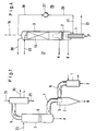
- a previous peroxide distillation plant according to FIG. 1 has a feed F (inlet) and two product outlets A and B, the pure peroxide solution being obtained at product outlet A.
- F 35%
- A 43% pure
- B 53% H2O2.
- the system has the individual components: evaporator 1, separator 2, distillation column 3 and condenser 4, which are connected by the bent connecting lines 6, 7, 8.
- This known system has relatively high pressure drops, firstly due to the bends and cross-sectional reductions in the connecting lines 6, 7, 8 and also in the components, for example in a cyclone 5 as a separator 2 and in the distillation column with trays 9
- Return 23 and to the condenser 4 a vacuum connection 30 and a cooling water inlet and outlet 24, 25 are connected.
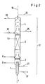
- FIGS. 2 and 3 show, schematically or in more detail, a peroxide distillation plant according to the invention, the components 1 to 4 being column-like, in direct succession are arranged in a vertical axis 16 and combined to form a structural unit 17.
- the evaporator 1 is directly connected to the separator 2 and this is built as an extension of the distillation column 3.
- the condenser 4 is placed on the distillation column 3.
- a riser evaporator 11 with a steam feed line 21 and a condensate drain 22, a lamellar liquid separator 12, a mixing condenser 14 with a complete counterflow principle and, above all, an ordered column packing 13 with a large surface area, for example a Sulzer packing, are used here as components with low flow resistance or pressure drop.
- the assembly 17 can consist of two parts which are joined together by means of only one flange 18. In this way, the tightness problems of previous, multi-assembled systems (FIG. 1) can also be overcome.
- the system can also be designed without a flange 18 as a one-piece, welded structural unit 17, for example with a manhole 33 for inspections.
- the system is preferably made entirely of pure aluminum or of stainless steel.
- the passage cross section 34 in the lower part of the column 3 can also be enlarged with a simultaneous widening 35 of the column wall.
- FIG. 4 shows a distillation plant according to the invention in which a heat pump 26 is used instead of the condenser 4.
- This consists of a compressor 27, for example as a one- or two-stage radial compressor, which is connected via lines 28, 29 to column 3 and evaporator 1 and which compresses the vapors of the column top to an increased (P, T) value to such an extent that this is sufficient to heat the evaporator 1.
- a heat pump of this type Only thanks to the design of the system according to the invention very low pressure drop, it is economically possible and sensible to use a heat pump of this type. With such a system according to FIG. 4, however, the operating costs can again be significantly reduced.
- FIG. 5 shows on the basis of a (P, T) diagram the improvement which can be achieved with systems (20) according to the invention compared to previous systems (10).
- 31 represents the vapor pressure curve of water and 32 the vapor pressure curve of an H2O2 solution.
- the point (P1, T1) with the pressure P1 and the temperature T1 indicates the top values in the condenser (or the distillation column for FIG. 4).
- P and T rise along the system according to arrows 10 for previous systems and 20 for systems according to the invention.
- the relatively high maximum values of previous systems are designated with (P2, T2).
- P3, P3) are generated with distillation plants according to the invention.
- the large pressure drop DP2 of a previous system is thus reduced to only a fraction corresponding to DP3 with systems according to the invention.
- the resulting reduction in temperature DT as well as the pressure drop DP mean corresponding massive improvements in plant safety and economy.
Landscapes
- Chemical & Material Sciences (AREA)
- Organic Chemistry (AREA)
- Inorganic Chemistry (AREA)
- Chemical Kinetics & Catalysis (AREA)
- Vaporization, Distillation, Condensation, Sublimation, And Cold Traps (AREA)
Claims (8)
- Installation de distillation pour la production de peroxyde d'hydrogène (H₂O₂) concentré, comportant comme composants un évaporateur (1), un séparateur de liquide (2) et une colonne de distillation (3), caractérisée en ce que les composants (1, 2, 3) sont disposés en succession dans un axe vertical (16) et sont réunis en une unité de construction (17) sans conduits de liaison entre les éléments (1, 2, 3), l'évaporateur (1) étant en prise directe sur l'évaporateur (2) et ce dernier étant monté comme prolongement de la colonne de distillation (3), en ce que touts les composants présentent une faible chute de pression et en ce que la colonne de distillation (3) présente une garniture ordonnée (13).
- Installation de distillation suivant la revendication 1, caractérisée par un condenseur (4) en tant qu'autre composant qui est monté directement sur la colonne de distillation (3) et qui est donc intégré à l'unité de construction (17).
- Colonne de distillation suivant la revendication 1, caractérisée par une pompe à chaleur (26) sous forme d'un compresseur (27) qui communique par des conduits (28, 29) avec la tête de la colonne de distillation (3) et l'évaporateur (1).
- Colonne de distillation suivant la revendication 2, caractérisée par un co-condenseur (14) opérant totalement suivant le principe du contre-courant.
- Installation de distillation suivant la revendication 1, caractérisée par un évaporateur (11) à tube ascendant.
- Installation de distillation suivant la revendication 1, caractérisée par un séparateur de liquide (12) à lamelles.
- Installation de distillation suivant la revendication 1, caractérisée en ce que la chute totale de pression (DP3) des composants s'élève à moins de 20 mbars.
- Utilisation d'une garniture ordonnée pour colonne de distillation (3) d'une installation de distillation suivant l'une des revendications 1 à 7.
Applications Claiming Priority (2)
| Application Number | Priority Date | Filing Date | Title |
|---|---|---|---|
| CH3462/89 | 1989-09-22 | ||
| CH346289 | 1989-09-22 |
Publications (2)
| Publication Number | Publication Date |
|---|---|
| EP0419406A1 EP0419406A1 (fr) | 1991-03-27 |
| EP0419406B1 true EP0419406B1 (fr) | 1993-10-20 |
Family
ID=4256466
Family Applications (1)
| Application Number | Title | Priority Date | Filing Date |
|---|---|---|---|
| EP90810677A Expired - Lifetime EP0419406B1 (fr) | 1989-09-22 | 1990-09-06 | Dispositif de distillation pour la fabrication d'eau oxygenée |
Country Status (5)
| Country | Link |
|---|---|
| US (1) | US5171407A (fr) |
| EP (1) | EP0419406B1 (fr) |
| JP (1) | JP2938952B2 (fr) |
| DE (1) | DE59003144D1 (fr) |
| FI (1) | FI94218C (fr) |
Cited By (1)
| Publication number | Priority date | Publication date | Assignee | Title |
|---|---|---|---|---|
| CN110860099A (zh) * | 2019-11-14 | 2020-03-06 | 聊城市鲁西化工工程设计有限责任公司 | 一种多品质双氧水提浓装置及其工艺和应用 |
Families Citing this family (18)
| Publication number | Priority date | Publication date | Assignee | Title |
|---|---|---|---|---|
| BE1005198A3 (fr) * | 1991-08-27 | 1993-05-25 | Solvay Interox | Procede pour l'obtention de solutions aqueuses epurees de peroxyde d'hydrogene. |
| FI960609L (fi) * | 1993-08-11 | 1996-02-09 | Conoco Specialty Prod | Peroxidin käsittelymenetelmä |
| JP3328854B2 (ja) * | 1993-09-13 | 2002-09-30 | 三菱瓦斯化学株式会社 | 過酸化水素の濃縮精製方法 |
| DE59610305D1 (de) * | 1996-10-09 | 2003-05-08 | Sulzer Chemtech Ag Winterthur | Destillationsanlage |
| EP1090663A1 (fr) * | 1999-10-05 | 2001-04-11 | SOLVAY (Société Anonyme) | Procédé de préparation de solutions concentrées |
| NL1013682C2 (nl) * | 1999-11-26 | 2001-05-30 | Purac Biochem Bv | Werkwijze en inrichting voor het zuiveren van een waterige oplossing van melkzuur. |
| DE10144013A1 (de) * | 2001-09-07 | 2003-03-27 | Basf Ag | Verfahren zur Aufarbeitung einer wässrigen Wasserstoffperoxid-Lösung aus einer Direktsynthese |
| RU2216505C2 (ru) * | 2001-12-07 | 2003-11-20 | ООО Научно-производственная фирма "Перам" | Способ выделения водных растворов пероксида водорода |
| ITBO20070104A1 (it) * | 2007-02-21 | 2008-08-22 | Kdvsistemi Brevetti S R L | Apparato per la produzione di combustibile sintetico |
| DE102010039748A1 (de) * | 2010-08-25 | 2012-03-01 | Evonik Degussa Gmbh | Verfahren zum Konzentrieren von wässriger Wasserstoffperoxidlösung |
| US10058796B2 (en) | 2012-12-10 | 2018-08-28 | Sulzer Chemtech Ag | Evaporator and process for use thereof |
| PL403721A1 (pl) | 2013-04-30 | 2014-11-10 | Instytut Lotnictwa | Sposób otrzymywania nadtlenku wodoru, zwłaszcza klasy HTP do zastosowań napędowych i układ do destylacji próżniowej |
| PL233084B1 (pl) * | 2015-07-14 | 2019-08-30 | Inst Lotnictwa | Jednostopniowy sposób otrzymywania nadtlenku wodoru klasy HTP ( High Test Peroxide) do zastosowań napędowych i układ do jego otrzymywania |
| CN110121480A (zh) | 2017-02-22 | 2019-08-13 | 三菱瓦斯化学株式会社 | 精制过氧化氢水溶液的制造方法和制造系统 |
| CL2021001192A1 (es) | 2020-05-28 | 2021-11-19 | Evonik Operations Gmbh | Dispositivo y proceso para producir peróxido de hidrógeno mediante un proceso de antraquinona |
| EP4063355A1 (fr) | 2021-03-22 | 2022-09-28 | Evonik Operations GmbH | Procédé et installation intégrés pour la fabrication de styrène et d'oxyde de propène |
| HUE071346T2 (hu) | 2021-05-10 | 2025-08-28 | Evonik Operations Gmbh | Integrált berendezés és integrált eljárás propén-oxid elõállítására |
| AU2022274987A1 (en) | 2021-05-10 | 2023-12-21 | Evonik Operations Gmbh | Optimized steam network for the ao process |
Family Cites Families (19)
| Publication number | Priority date | Publication date | Assignee | Title |
|---|---|---|---|---|
| FR563908A (fr) * | 1922-06-29 | 1923-12-17 | Procédé et dispositifs pour la fabrication continue d'eau oxygénée (peroxyde d'hydrogène) de toute concentration voulue | |
| US2300985A (en) * | 1939-12-28 | 1942-11-03 | Sinclair Refining Co | Distillation |
| US2298064A (en) * | 1939-12-29 | 1942-10-06 | Mathieson Alkali Works Inc | Chemical manufacture |
| US2543001A (en) * | 1942-08-15 | 1951-02-27 | Foster Wheeler Corp | Continuous distillation and treatment of composite liquids |
| US2715607A (en) * | 1949-09-22 | 1955-08-16 | Lee Foundation For Nutritional | Knockdown distillation apparatus |
| NL176744B (nl) * | 1952-04-24 | Helopharm Petrik Co Kg | Werkwijze voor de bereiding van tegen orthostatische dysregulatie werkzame preparaten. | |
| DE1025833B (de) * | 1952-12-19 | 1958-03-13 | Metallgesellschaft Ag | Verfahren zur Kondensation von Gemischen aus Wasserdampf und organischen Daempfen |
| US3073755A (en) * | 1959-08-11 | 1963-01-15 | Laporte Chemical | Concentration of hydrogen peroxide |
| DE1110143B (de) * | 1960-04-12 | 1961-07-06 | Kali Chemie Ag | Verfahren zum Konzentrieren verduennter waessriger Wasserstoffperoxydloesungen |
| DE1114168B (de) * | 1960-08-03 | 1961-09-28 | Bayer Ag | Destillationsvorrichtung mit Waermepumpe |
| DE1493688A1 (de) * | 1965-01-13 | 1969-06-19 | Bayer Ag | Verfahren und Vorrichtung zur Herstellung von 1,3,5-Trioxan hoechster Reinheit |
| US3445343A (en) * | 1967-02-01 | 1969-05-20 | Dmitry Mikhailovich Popov | Apparatus for evaporating-condensing separation of mixtures |
| AT274743B (de) * | 1967-09-28 | 1969-09-25 | Krems Chemie Gmbh | Verfahren und Vorrichtung zur kontinuierlichen Fraktionierung von Tallöl oder andern organischen Mehrstoffgemischen |
| US3755088A (en) * | 1969-08-04 | 1973-08-28 | Hydro Chem & Mineral Corp | Internally interconnected multi-stage distillation system |
| US3820582A (en) * | 1970-12-14 | 1974-06-28 | Rosenlew Ab Metallind O | Device for evaporation of liquids |
| US3961658A (en) * | 1972-07-07 | 1976-06-08 | Snam Progetti S.P.A. | Sea water desalination apparatus |
| US4575403A (en) * | 1982-06-04 | 1986-03-11 | Fmc Corporation | Apparatus for distilling phosphorus |
| SU1121018A1 (ru) * | 1983-05-19 | 1984-10-30 | Рижский Ордена Трудового Красного Знамени Политехнический Институт | Ректификационна установка |
| CA1228324A (fr) * | 1984-03-07 | 1987-10-20 | Hans Becker | Methode et installation de distillation et(ou) d'extraction |
-
1990
- 1990-08-21 US US07/570,209 patent/US5171407A/en not_active Expired - Lifetime
- 1990-08-23 FI FI904181A patent/FI94218C/fi active IP Right Grant
- 1990-09-06 EP EP90810677A patent/EP0419406B1/fr not_active Expired - Lifetime
- 1990-09-06 DE DE90810677T patent/DE59003144D1/de not_active Expired - Fee Related
- 1990-09-19 JP JP2247641A patent/JP2938952B2/ja not_active Expired - Fee Related
Cited By (2)
| Publication number | Priority date | Publication date | Assignee | Title |
|---|---|---|---|---|
| CN110860099A (zh) * | 2019-11-14 | 2020-03-06 | 聊城市鲁西化工工程设计有限责任公司 | 一种多品质双氧水提浓装置及其工艺和应用 |
| CN110860099B (zh) * | 2019-11-14 | 2022-03-04 | 聊城市鲁西化工工程设计有限责任公司 | 一种多品质双氧水提浓装置及其工艺和应用 |
Also Published As
| Publication number | Publication date |
|---|---|
| FI94218B (fi) | 1995-04-28 |
| US5171407A (en) | 1992-12-15 |
| FI94218C (fi) | 1995-08-10 |
| FI904181A0 (fi) | 1990-08-23 |
| DE59003144D1 (de) | 1993-11-25 |
| EP0419406A1 (fr) | 1991-03-27 |
| JP2938952B2 (ja) | 1999-08-25 |
| JPH03122005A (ja) | 1991-05-24 |
Similar Documents
| Publication | Publication Date | Title |
|---|---|---|
| EP0419406B1 (fr) | Dispositif de distillation pour la fabrication d'eau oxygenée | |
| DE69529146T2 (de) | Destillationskolonne mit innerem wärmeaustausch | |
| DE3302525A1 (de) | Destillationskolonne zur destillativen zerlegung eines aus mehreren fraktionen bestehenden zulaufproduktes | |
| WO1993019336A1 (fr) | Procede de separation d'air a basse temperature et installation de separation d'air | |
| EP0461515B1 (fr) | Dispositif de chauffage et de dégazage de l'eau | |
| DE2133807B2 (de) | Mehrstufiger Sprühfilmverdampfer zur Gewinnung von Brauchwasser aus Rohwasser | |
| EP0781583A2 (fr) | Procédé et dispositif de chauffage et de déaération multiple de l'eau | |
| DE60313250T2 (de) | Wärmeintegrierte Destillationskolonne | |
| DE2441384A1 (de) | Zwangsumlaufverdampfer | |
| EP1329449A1 (fr) | Colonne de concentration de l'anhydride phtalique | |
| DE3244521A1 (de) | Vorrichtung zum kontaktieren von gasen und fluessigkeiten | |
| EP0425941B1 (fr) | Dispositif de dégazage et de chauffage d'eau | |
| DE1212231B (de) | System aus einem Siedewasser-Reaktor mit direkt angeschlossener Turbine und Verfahren zur Regelung eines derartigen Systems | |
| DE2633272A1 (de) | Rektifiziereinrichtung | |
| DE1170908B (de) | Kontaktturm fuer Gase und Fluessigkeiten | |
| DE3133803A1 (de) | Vorrichtung zum konzentrieren waessriger loesungen von glykol | |
| DE3236985C2 (fr) | ||
| DE10005750C2 (de) | Kolonne zur Trennung von Gemischen, welche aus mindestens 3 unterschiedlichen Komponenten bestehen | |
| DE10135716A1 (de) | Verbesserter Fallfilmverdampfer zur Auftrennung von Stoffgemischen | |
| EP0729772A2 (fr) | Evaporateur | |
| DE2358349A1 (de) | Zweistufiger niederdruckvorwaermer | |
| DE1257739B (de) | Verfahren zum gleichzeitigen Fraktionieren in einer Destillationskolonne von mindestens zwei sich in ihren Siedebereichen nicht ueberschneidenden Einsatzstroemen | |
| DE19524216A1 (de) | Anlage für die Vorwärmung und Entgasung von Wasser | |
| DE2458382B1 (de) | Speisewasservorwaermer mit zwei dampfraeumen | |
| DE3837081C2 (de) | Verfahren zur Entnahme von Destillat genügend heißen Zustands in mehrstufigen Destillationsvorrichtungen |
Legal Events
| Date | Code | Title | Description |
|---|---|---|---|
| PUAI | Public reference made under article 153(3) epc to a published international application that has entered the european phase |
Free format text: ORIGINAL CODE: 0009012 |
|
| 17P | Request for examination filed |
Effective date: 19901112 |
|
| AK | Designated contracting states |
Kind code of ref document: A1 Designated state(s): CH DE FR IT LI SE |
|
| 17Q | First examination report despatched |
Effective date: 19930210 |
|
| GRAA | (expected) grant |
Free format text: ORIGINAL CODE: 0009210 |
|
| ITF | It: translation for a ep patent filed | ||
| AK | Designated contracting states |
Kind code of ref document: B1 Designated state(s): CH DE FR IT LI SE |
|
| RAP2 | Party data changed (patent owner data changed or rights of a patent transferred) |
Owner name: SULZER CHEMTECH AG |
|
| REF | Corresponds to: |
Ref document number: 59003144 Country of ref document: DE Date of ref document: 19931125 |
|
| ET | Fr: translation filed | ||
| PLBE | No opposition filed within time limit |
Free format text: ORIGINAL CODE: 0009261 |
|
| STAA | Information on the status of an ep patent application or granted ep patent |
Free format text: STATUS: NO OPPOSITION FILED WITHIN TIME LIMIT |
|
| 26N | No opposition filed | ||
| EAL | Se: european patent in force in sweden |
Ref document number: 90810677.6 |
|
| PGFP | Annual fee paid to national office [announced via postgrant information from national office to epo] |
Ref country code: CH Payment date: 20080915 Year of fee payment: 19 |
|
| PGFP | Annual fee paid to national office [announced via postgrant information from national office to epo] |
Ref country code: FR Payment date: 20080912 Year of fee payment: 19 Ref country code: IT Payment date: 20080925 Year of fee payment: 19 |
|
| PGFP | Annual fee paid to national office [announced via postgrant information from national office to epo] |
Ref country code: DE Payment date: 20080919 Year of fee payment: 19 |
|
| PGFP | Annual fee paid to national office [announced via postgrant information from national office to epo] |
Ref country code: SE Payment date: 20080912 Year of fee payment: 19 |
|
| REG | Reference to a national code |
Ref country code: CH Ref legal event code: PL |
|
| EUG | Se: european patent has lapsed | ||
| REG | Reference to a national code |
Ref country code: FR Ref legal event code: ST Effective date: 20100531 |
|
| PG25 | Lapsed in a contracting state [announced via postgrant information from national office to epo] |
Ref country code: DE Free format text: LAPSE BECAUSE OF NON-PAYMENT OF DUE FEES Effective date: 20100401 Ref country code: FR Free format text: LAPSE BECAUSE OF NON-PAYMENT OF DUE FEES Effective date: 20090930 |
|
| PG25 | Lapsed in a contracting state [announced via postgrant information from national office to epo] |
Ref country code: CH Free format text: LAPSE BECAUSE OF NON-PAYMENT OF DUE FEES Effective date: 20090930 Ref country code: LI Free format text: LAPSE BECAUSE OF NON-PAYMENT OF DUE FEES Effective date: 20090930 |
|
| PG25 | Lapsed in a contracting state [announced via postgrant information from national office to epo] |
Ref country code: IT Free format text: LAPSE BECAUSE OF NON-PAYMENT OF DUE FEES Effective date: 20090906 |
|
| PG25 | Lapsed in a contracting state [announced via postgrant information from national office to epo] |
Ref country code: SE Free format text: LAPSE BECAUSE OF NON-PAYMENT OF DUE FEES Effective date: 20090907 |