EP0419714A1 - Dossier avec un support lombo-sacré réglable en hauteur - Google Patents
Dossier avec un support lombo-sacré réglable en hauteur Download PDFInfo
- Publication number
- EP0419714A1 EP0419714A1 EP89118003A EP89118003A EP0419714A1 EP 0419714 A1 EP0419714 A1 EP 0419714A1 EP 89118003 A EP89118003 A EP 89118003A EP 89118003 A EP89118003 A EP 89118003A EP 0419714 A1 EP0419714 A1 EP 0419714A1
- Authority
- EP
- European Patent Office
- Prior art keywords
- backrest
- cushion
- support part
- cushion plate
- lordosis
- Prior art date
- Legal status (The legal status is an assumption and is not a legal conclusion. Google has not performed a legal analysis and makes no representation as to the accuracy of the status listed.)
- Granted
Links
- 208000007623 Lordosis Diseases 0.000 claims description 31
- 230000000284 resting effect Effects 0.000 claims description 2
- 238000006073 displacement reaction Methods 0.000 claims 1
- 238000010276 construction Methods 0.000 abstract description 6
- 238000011161 development Methods 0.000 description 4
- 230000018109 developmental process Effects 0.000 description 4
- 230000008859 change Effects 0.000 description 2
- 238000005253 cladding Methods 0.000 description 2
- 230000008878 coupling Effects 0.000 description 2
- 238000010168 coupling process Methods 0.000 description 2
- 238000005859 coupling reaction Methods 0.000 description 2
- 239000006260 foam Substances 0.000 description 2
- 229910000831 Steel Inorganic materials 0.000 description 1
- 230000006978 adaptation Effects 0.000 description 1
- 230000008901 benefit Effects 0.000 description 1
- 239000003814 drug Substances 0.000 description 1
- 230000008030 elimination Effects 0.000 description 1
- 238000003379 elimination reaction Methods 0.000 description 1
- 239000004744 fabric Substances 0.000 description 1
- 210000004705 lumbosacral region Anatomy 0.000 description 1
- 238000000034 method Methods 0.000 description 1
- 230000009467 reduction Effects 0.000 description 1
- 239000010959 steel Substances 0.000 description 1
- 208000024891 symptom Diseases 0.000 description 1
- 230000007704 transition Effects 0.000 description 1
- 230000000007 visual effect Effects 0.000 description 1
Images


Classifications
-
- A—HUMAN NECESSITIES
- A47—FURNITURE; DOMESTIC ARTICLES OR APPLIANCES; COFFEE MILLS; SPICE MILLS; SUCTION CLEANERS IN GENERAL
- A47C—CHAIRS; SOFAS; BEDS
- A47C7/00—Parts, details, or accessories of chairs or stools
- A47C7/36—Supports for the head or the back
- A47C7/40—Supports for the head or the back for the back
- A47C7/46—Supports for the head or the back for the back with special, e.g. adjustable, lumbar region support profile; "Ackerblom" profile chairs
- A47C7/462—Supports for the head or the back for the back with special, e.g. adjustable, lumbar region support profile; "Ackerblom" profile chairs adjustable by mechanical means
Definitions
- Such a backrest is known for example from DE-A1 36 34 500.
- the aim of such adjustment devices is that precise support in the area of the lower lumbar vertebrae (lumbar lordosis area) of the respective user is achieved with a cushion which is shaped in accordance with the shape of the spine. Correct support of the back is an essential prerequisite for sitting longer periods without symptoms.
- the entire backrest also has to be moved, which is often - due to its own weight - also due to tilting difficult in leadership.
- actuation with two hands remains unavoidable: while one hand operates the lock, the other positions the backrest in the desired position. Constructions can also be found in which an operation while sitting is impossible due to the difficult to reach or difficult operating elements.
- the carrier shell has to be made in several pieces in a complex manner, which on the one hand impairs the stability of the backrest and on the other hand limits the adjustment range.
- the object of the present invention is now to provide a height-adjustable backrest which avoids the disadvantages of previous solutions described above and is characterized in particular by body-adjustable adjustability with simplified handling and reduced construction costs.
- the vertical adjustment of the lumbar area of the backrest for office armchairs of type D according to DIN 4551 should be designed to be at least as large as it seems advisable for type A working chairs in DIN 4551; - allow the adjustment without the user having to rise from the chair or move far from the backrest; - To achieve a substantial reduction in construction costs and weight; - to implement the necessary structural measures to the advantage for the visual overall impression of the chair; and - In the context of a modular system, a vertical or horizontal profile change separately or to be combined in a closed system.
- the task is solved in a backrest of the type mentioned in that (d) the lumbar support part is displaceable in the vertical direction relative to the backrest cushion and to the cushion plate.
- the essence of the invention is therefore that a compact segment placed on the back of the cushion and integrated into the backrest can be moved up and down separately by means of an adjusting member.
- the segment is designed in such a way that, in the middle position of its adjustment range, it complements the backrest upholstery to a shape aimed at a medium-sized person; From this standard setting, it can now be adapted to large and small owners by moving it up or down.
- the zone of maximum protrusion on the front of the cushion thus shifts up or down; This enables a wide range of adaptations to anatomical conditions in humans under ergonomic criteria.
- the adjustment is made easier for the user by the fact that the entire backrest no longer has to be moved up and down, but rather only a single part with a comparatively low weight is moved under the cushion cover.
- a preferred development of the invention is characterized in that additional means are provided for changing the bulging of the backrest cushion by moving the lumbar support part back and forth.
- the lordosis support part can either be coupled with its linear vertical movement or independently of it perform the additional horizontal movement.
- the height adjustability takes into account individual body size and trunk proportions and therefore has a clear priority. According to occupational medicine recommendations, the height adjustment should cover a range of approx. 70 mm.
- the additional adjustability of the protrusion in the horizontal direction proves to be useful for people whose spine profile in the lumbar region deviates from a normal shape (arched further forward or flatter).
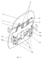
- FIG. 1 shows a front view and with the backrest cushion removed
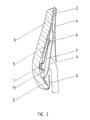
- FIG. 2 shows a longitudinal section (with cushion), the construction of a backrest with height-adjustable lumbar support area according to a preferred embodiment of the invention.
- An example of conventionally designed upholstery consisting of a one-piece cushion plate 2 and a one-piece backrest cushion 3 (which comprises a foam pad and a cover fabric), has a recess 2a in the cushion plate 2 on the back, which has a curved, one-piece lordosis support part 1 with the takes up the necessary freedom of movement.
- the lumbar support part 1 presses through the recess 2a directly onto the backrest cushion 3.
- a tensioned separating film 5 is preferably provided between the cushion and the lordosis support part 1, which e.g. can be glued to the backrest cushion 3 on the foam side.
- Attached flags 11, which are part of the cushion plate 2 and can be guided in the lordosis support part 1, ensure that the owner feels an even pressure distribution on the cushion, even when the lordosis support part 1 is in the lowest position.
- the lugs 11 bridge the changing gap between the lordosis support part 1 and the cushion plate 2. When the lordosis support part 1 is in the highest position, the pressure forces, which are anyway low in the lower region of the backrest, are transmitted by the lugs 11 projecting downwards.
- a controlled movement of the lordosis support part 1 is made possible via suitable guideways 7 (FIG. 2), for example ribs, and the leaning forces of the seated person are derived into a support structure 9 which supports the backrest in this exemplary embodiment.
- an adjusting element in the form of a lever arm 6 engages the lordosis support part 1; the lever arm 6 is mounted in a pivot point 8 which is fixed to the cushion plate 2 laterally from the recess 2a and, on the other side, emerges from a covering 4 from or under the cushion. It is operated by means of a key 10.
- a locking element 23 is provided, which is arranged displaceably on the lever arm 6 and is pressed by means of a spring 24 against a corresponding locking bar 22 in the casing 4.
- a suitable design of the lever ratios between the pivot point, the point of application on the lordosis support part 1 and the button 10 ensures that the button 10 can be actuated smoothly.
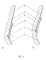
- the adjustment range achieved, characterized by the upper and lower positions of the lordosis support part 1, is shown in FIGS. 3a, b.
- An additional horizontal adjustment of the movable lordosis support part 1 can take place in a further embodiment of the backrest according to the invention such that the base on which the wedge-shaped lordosis support part 1 is guided is changed horizontally (FIG. 4).
- the adjustment can be maintained with the lever arm 6 described, the driver on the lordosis support part 1 either by a link-like configuration tion or even more advantageously compensates for the horizontal movement that occurs due to its inherent elasticity in the horizontal direction (for example in the case of a spring band steel version).
- cranks 12 in the form of bent wire parts can be used here. Acting as a parallelogram, they are rotatably supported on the one hand by means of crank bearings 20 on the cushion plate 2 or the supporting structure 9. On the other hand, they engage in guides 15 on the lordosis support part 1 via rails 15a.
- cranks 12 are moved up and down via a coupling part 14, which results in the desired, exactly parallel, horizontal movement for the guides 15 and thus for the wedge.
- a further simplification was represented by a single, centrally arranged crank which is acted upon directly by the actuating lever 6a.
- a disturbing tilting of the lordosis support part 1 is effectively prevented by the flags 11 of the cushion plate 2, which penetrate the lordosis support part 1.
- an additional horizontal adjustment can take place in such a way that the horizontal movement is initiated via a handwheel 18 and a shaft 17 which is mounted on the supporting structure 9 by means of shaft bearings 21.
- Polygonal cams 16 are preferably arranged on the shaft 17 with a center distance increasing from cam surface to cam surface, which determine the distance between shaft 17 and lumbar support part 1 and thus the desired on ensure adjustability of the protrusion.
- Rails 19 are provided for vertical guidance.
- the flags 11 stabilize the lordosis support part 1.
- the lordosis support part 1 can be acted upon directly on the rear side if the guides 15 on the one hand and the rails 19 on the other hand are made deeper than the horizontal adjustment path.
- the lumbar support part 1 lies movably within the structural unit comprising the backrest cushion 3 and the cushion plate 2, but the adjustment element acts outside and only on the back of the lordosis support part 1.
- the backrest cladding can also be self-supporting; the supporting structure 9 can therefore possibly be omitted, i.e. be an integral part of the backrest cover.
- the height adjustment can also be done by a roller-shaped button or a slide on the outside of the panel 4; A structural simplification would then result from the elimination of the lever arm 6 and the pivot point 8.
- the inclination of the guideway 7 can also be varied such that there is a correlation between lower seat depth for low or greater seat depth for lumbar support 1.
- the slidable part can also be designed as a padded, separate part.
Landscapes
- Engineering & Computer Science (AREA)
- Mechanical Engineering (AREA)
- Chair Legs, Seat Parts, And Backrests (AREA)
- Special Chairs (AREA)
- Mattresses And Other Support Structures For Chairs And Beds (AREA)
Priority Applications (4)
| Application Number | Priority Date | Filing Date | Title |
|---|---|---|---|
| DE8915853U DE8915853U1 (de) | 1989-09-28 | 1989-09-28 | Rückenlehne mit einer höhenverstellbaren Lendenlordosen-Unterstützung |
| DE8989118003T DE58904653D1 (de) | 1989-09-28 | 1989-09-28 | Rueckenlehne mit einer hoehenverstellbaren lendenlordosen-unterstuetzung. |
| AT89118003T ATE90187T1 (de) | 1989-09-28 | 1989-09-28 | Rueckenlehne mit einer hoehenverstellbaren lendenlordosen-unterstuetzung. |
| EP89118003A EP0419714B1 (fr) | 1989-09-28 | 1989-09-28 | Dossier avec un support lombo-sacré réglable en hauteur |
Applications Claiming Priority (1)
| Application Number | Priority Date | Filing Date | Title |
|---|---|---|---|
| EP89118003A EP0419714B1 (fr) | 1989-09-28 | 1989-09-28 | Dossier avec un support lombo-sacré réglable en hauteur |
Publications (2)
| Publication Number | Publication Date |
|---|---|
| EP0419714A1 true EP0419714A1 (fr) | 1991-04-03 |
| EP0419714B1 EP0419714B1 (fr) | 1993-06-09 |
Family
ID=8201946
Family Applications (1)
| Application Number | Title | Priority Date | Filing Date |
|---|---|---|---|
| EP89118003A Expired - Lifetime EP0419714B1 (fr) | 1989-09-28 | 1989-09-28 | Dossier avec un support lombo-sacré réglable en hauteur |
Country Status (3)
| Country | Link |
|---|---|
| EP (1) | EP0419714B1 (fr) |
| AT (1) | ATE90187T1 (fr) |
| DE (2) | DE58904653D1 (fr) |
Cited By (8)
| Publication number | Priority date | Publication date | Assignee | Title |
|---|---|---|---|---|
| WO1994007393A1 (fr) * | 1992-09-29 | 1994-04-14 | Ameu-Management Corp. | Dossier d'un siege avec dispositif de reglage d'un element de courbure elastique permettant de regler la courbure du dossier |
| EP0897682A1 (fr) * | 1997-08-14 | 1999-02-24 | Wilhelm Ing. Schuster | Corps formé |
| WO1999063869A1 (fr) * | 1998-06-05 | 1999-12-16 | Teknion Furniture Systems | Mecanisme de reglage d'appui lombaire |
| WO2004032686A1 (fr) * | 2002-10-08 | 2004-04-22 | Pro-Cord Spa | Dossier de chaise |
| EP1563768A1 (fr) * | 2004-02-13 | 2005-08-17 | Schukra Gerätebau AG | Support réglable en hauteur |
| WO2006010552A1 (fr) * | 2004-07-22 | 2006-02-02 | Bock 1 Gmbh & Co. Kg | Siege, notamment chaise de bureau |
| GB2400028B (en) * | 2002-01-28 | 2006-04-05 | Brock M Walker | Sacral support member for seating |
| US10264890B2 (en) | 2015-06-29 | 2019-04-23 | Herman Miller, Inc. | Back support |
Families Citing this family (3)
| Publication number | Priority date | Publication date | Assignee | Title |
|---|---|---|---|---|
| DE4227246C2 (de) * | 1991-08-21 | 1994-04-28 | Wingerter Hans Joachim | Gepolsterte Rückenlehne für einen Stuhl |
| DE10055951B4 (de) * | 1999-12-15 | 2006-02-23 | Institut für Holztechnologie Dresden gGmbH | Sitzmöbel |
| DE102006008235B4 (de) * | 2006-02-22 | 2014-12-11 | Volkswagen Ag | Sitz, insbesondere Kraftfahrzeugsitz |
Citations (6)
| Publication number | Priority date | Publication date | Assignee | Title |
|---|---|---|---|---|
| US3948558A (en) * | 1975-03-31 | 1976-04-06 | Deere & Company | Seat backrest having an adjustable lumbar support |
| GB2107576A (en) * | 1981-10-16 | 1983-05-05 | Brian Barr Richardson | Adjustable seat back |
| GB2112277A (en) * | 1981-10-21 | 1983-07-20 | Stylex Motor Products Limited | Vehicle seats |
| US4502728A (en) * | 1982-10-08 | 1985-03-05 | Nepsco, Inc. | Portable seat and back rest |
| US4725095A (en) * | 1986-07-11 | 1988-02-16 | Johnson Service Company | Vehicle seat with mechanical lumbar support having two degrees of freedom |
| GB2196530A (en) * | 1986-11-01 | 1988-05-05 | Jmh Holdings Ltd | A seat with a movable lumbar support device |
-
1989
- 1989-09-28 DE DE8989118003T patent/DE58904653D1/de not_active Expired - Fee Related
- 1989-09-28 EP EP89118003A patent/EP0419714B1/fr not_active Expired - Lifetime
- 1989-09-28 AT AT89118003T patent/ATE90187T1/de not_active IP Right Cessation
- 1989-09-28 DE DE8915853U patent/DE8915853U1/de not_active Expired - Lifetime
Patent Citations (6)
| Publication number | Priority date | Publication date | Assignee | Title |
|---|---|---|---|---|
| US3948558A (en) * | 1975-03-31 | 1976-04-06 | Deere & Company | Seat backrest having an adjustable lumbar support |
| GB2107576A (en) * | 1981-10-16 | 1983-05-05 | Brian Barr Richardson | Adjustable seat back |
| GB2112277A (en) * | 1981-10-21 | 1983-07-20 | Stylex Motor Products Limited | Vehicle seats |
| US4502728A (en) * | 1982-10-08 | 1985-03-05 | Nepsco, Inc. | Portable seat and back rest |
| US4725095A (en) * | 1986-07-11 | 1988-02-16 | Johnson Service Company | Vehicle seat with mechanical lumbar support having two degrees of freedom |
| GB2196530A (en) * | 1986-11-01 | 1988-05-05 | Jmh Holdings Ltd | A seat with a movable lumbar support device |
Cited By (14)
| Publication number | Priority date | Publication date | Assignee | Title |
|---|---|---|---|---|
| AU684472B2 (en) * | 1992-09-29 | 1997-12-18 | Schukra-Geratebau Gmbh | Seat back with an adjustment device for an elastic element enabling the arch of the back to be adjusted |
| WO1994007393A1 (fr) * | 1992-09-29 | 1994-04-14 | Ameu-Management Corp. | Dossier d'un siege avec dispositif de reglage d'un element de courbure elastique permettant de regler la courbure du dossier |
| EP0897682A1 (fr) * | 1997-08-14 | 1999-02-24 | Wilhelm Ing. Schuster | Corps formé |
| WO1999008570A3 (fr) * | 1997-08-14 | 1999-06-03 | Wilhelm Schuster | Corps moule |
| WO1999063869A1 (fr) * | 1998-06-05 | 1999-12-16 | Teknion Furniture Systems | Mecanisme de reglage d'appui lombaire |
| US6260921B1 (en) | 1998-06-05 | 2001-07-17 | Teknion Furniture Systems, Inc. | Lumbar support adjustment mechanism |
| GB2400028B (en) * | 2002-01-28 | 2006-04-05 | Brock M Walker | Sacral support member for seating |
| US7878591B2 (en) | 2002-01-28 | 2011-02-01 | Herman Miller Inc. | Sacral support member for seating |
| WO2004032686A1 (fr) * | 2002-10-08 | 2004-04-22 | Pro-Cord Spa | Dossier de chaise |
| DE102004007175B4 (de) * | 2004-02-13 | 2006-02-16 | Schukra Gerätebau AG | Höhenverstellbare Stützvorrichtung |
| DE102004007175A1 (de) * | 2004-02-13 | 2005-09-01 | Schukra Gerätebau AG | Höhenverstellbare Stützvorrichtung |
| EP1563768A1 (fr) * | 2004-02-13 | 2005-08-17 | Schukra Gerätebau AG | Support réglable en hauteur |
| WO2006010552A1 (fr) * | 2004-07-22 | 2006-02-02 | Bock 1 Gmbh & Co. Kg | Siege, notamment chaise de bureau |
| US10264890B2 (en) | 2015-06-29 | 2019-04-23 | Herman Miller, Inc. | Back support |
Also Published As
| Publication number | Publication date |
|---|---|
| DE8915853U1 (de) | 1992-01-23 |
| DE58904653D1 (de) | 1993-07-15 |
| EP0419714B1 (fr) | 1993-06-09 |
| ATE90187T1 (de) | 1993-06-15 |
Similar Documents
| Publication | Publication Date | Title |
|---|---|---|
| EP1712410B1 (fr) | Siège de véhicule à dossier deformable | |
| DE3822574C2 (fr) | ||
| EP0265782A2 (fr) | Siège | |
| EP0017253A1 (fr) | Meuble d'assise | |
| DE4135948A1 (de) | Stuhl, insbesondere buerodrehstuhl | |
| EP0419714B1 (fr) | Dossier avec un support lombo-sacré réglable en hauteur | |
| DE69022856T2 (de) | Verstellbarer stuhl. | |
| EP1302134B1 (fr) | Chaise à profondeur variable | |
| EP2301796B1 (fr) | Siège de véhicule doté d'un dossier à contour déformable | |
| EP3968823B1 (fr) | Système réglable en hauteur de support de nuque pour une chaise de jeu | |
| DE2065536C3 (de) | Rückenlehne, insbesondere für Sitzmöbel | |
| DE4424096A1 (de) | Stuhl | |
| DE10133132A1 (de) | Armstütze für Stühle | |
| DE8100597U1 (de) | Sitzmoebel | |
| EP0347538A1 (fr) | Chaise, notamment chaise de bureau | |
| DE3002182C2 (de) | Stuhl, insbesondere Arbeitsstuhl bzw. Steharbeitssitz | |
| EP1306033B1 (fr) | Chaise | |
| DE8620791U1 (de) | Verstellbarer Fahrzeugsitz | |
| EP0071710A2 (fr) | Chaise de bureau avec siège et dossier réglable | |
| EP1699319A1 (fr) | Meuble permettant de s' assoir ou de se coucher | |
| WO2018114515A1 (fr) | Chaise, de préférence chaise pivotante | |
| EP1166682B1 (fr) | Siège | |
| DE29516840U1 (de) | Rückstellvorrichtung für einen Stuhl | |
| DE4027730A1 (de) | Sitzmoebel | |
| DE29615298U1 (de) | Sitzmöbel |
Legal Events
| Date | Code | Title | Description |
|---|---|---|---|
| PUAI | Public reference made under article 153(3) epc to a published international application that has entered the european phase |
Free format text: ORIGINAL CODE: 0009012 |
|
| AK | Designated contracting states |
Kind code of ref document: A1 Designated state(s): AT CH DE FR GB IT LI NL |
|
| 17P | Request for examination filed |
Effective date: 19910531 |
|
| 17Q | First examination report despatched |
Effective date: 19921113 |
|
| GRAA | (expected) grant |
Free format text: ORIGINAL CODE: 0009210 |
|
| AK | Designated contracting states |
Kind code of ref document: B1 Designated state(s): AT CH DE FR GB IT LI NL |
|
| REF | Corresponds to: |
Ref document number: 90187 Country of ref document: AT Date of ref document: 19930615 Kind code of ref document: T |
|
| REF | Corresponds to: |
Ref document number: 58904653 Country of ref document: DE Date of ref document: 19930715 |
|
| ET | Fr: translation filed | ||
| ITF | It: translation for a ep patent filed | ||
| GBT | Gb: translation of ep patent filed (gb section 77(6)(a)/1977) |
Effective date: 19930813 |
|
| PLBE | No opposition filed within time limit |
Free format text: ORIGINAL CODE: 0009261 |
|
| STAA | Information on the status of an ep patent application or granted ep patent |
Free format text: STATUS: NO OPPOSITION FILED WITHIN TIME LIMIT |
|
| 26N | No opposition filed | ||
| REG | Reference to a national code |
Ref country code: GB Ref legal event code: IF02 |
|
| PGFP | Annual fee paid to national office [announced via postgrant information from national office to epo] |
Ref country code: GB Payment date: 20030827 Year of fee payment: 15 |
|
| PGFP | Annual fee paid to national office [announced via postgrant information from national office to epo] |
Ref country code: NL Payment date: 20030828 Year of fee payment: 15 |
|
| PGFP | Annual fee paid to national office [announced via postgrant information from national office to epo] |
Ref country code: AT Payment date: 20030829 Year of fee payment: 15 |
|
| PGFP | Annual fee paid to national office [announced via postgrant information from national office to epo] |
Ref country code: CH Payment date: 20030901 Year of fee payment: 15 |
|
| PGFP | Annual fee paid to national office [announced via postgrant information from national office to epo] |
Ref country code: DE Payment date: 20030903 Year of fee payment: 15 |
|
| PGFP | Annual fee paid to national office [announced via postgrant information from national office to epo] |
Ref country code: FR Payment date: 20030904 Year of fee payment: 15 |
|
| PG25 | Lapsed in a contracting state [announced via postgrant information from national office to epo] |
Ref country code: GB Free format text: LAPSE BECAUSE OF NON-PAYMENT OF DUE FEES Effective date: 20040928 Ref country code: AT Free format text: LAPSE BECAUSE OF NON-PAYMENT OF DUE FEES Effective date: 20040928 |
|
| PG25 | Lapsed in a contracting state [announced via postgrant information from national office to epo] |
Ref country code: LI Free format text: LAPSE BECAUSE OF NON-PAYMENT OF DUE FEES Effective date: 20040930 Ref country code: CH Free format text: LAPSE BECAUSE OF NON-PAYMENT OF DUE FEES Effective date: 20040930 |
|
| PG25 | Lapsed in a contracting state [announced via postgrant information from national office to epo] |
Ref country code: NL Free format text: LAPSE BECAUSE OF NON-PAYMENT OF DUE FEES Effective date: 20050401 Ref country code: DE Free format text: LAPSE BECAUSE OF NON-PAYMENT OF DUE FEES Effective date: 20050401 |
|
| REG | Reference to a national code |
Ref country code: CH Ref legal event code: PL |
|
| GBPC | Gb: european patent ceased through non-payment of renewal fee |
Effective date: 20040928 |
|
| PG25 | Lapsed in a contracting state [announced via postgrant information from national office to epo] |
Ref country code: FR Free format text: LAPSE BECAUSE OF NON-PAYMENT OF DUE FEES Effective date: 20050531 |
|
| NLV4 | Nl: lapsed or anulled due to non-payment of the annual fee |
Effective date: 20050401 |
|
| REG | Reference to a national code |
Ref country code: FR Ref legal event code: ST |
|
| PG25 | Lapsed in a contracting state [announced via postgrant information from national office to epo] |
Ref country code: IT Free format text: LAPSE BECAUSE OF NON-PAYMENT OF DUE FEES;WARNING: LAPSES OF ITALIAN PATENTS WITH EFFECTIVE DATE BEFORE 2007 MAY HAVE OCCURRED AT ANY TIME BEFORE 2007. THE CORRECT EFFECTIVE DATE MAY BE DIFFERENT FROM THE ONE RECORDED. Effective date: 20050928 |