EP0419738A1 - Procédé et dispositif pour la fabrication d'articles allongés - Google Patents
Procédé et dispositif pour la fabrication d'articles allongés Download PDFInfo
- Publication number
- EP0419738A1 EP0419738A1 EP89309760A EP89309760A EP0419738A1 EP 0419738 A1 EP0419738 A1 EP 0419738A1 EP 89309760 A EP89309760 A EP 89309760A EP 89309760 A EP89309760 A EP 89309760A EP 0419738 A1 EP0419738 A1 EP 0419738A1
- Authority
- EP
- European Patent Office
- Prior art keywords
- orifice
- segment
- common
- synthetic resin
- cross
- Prior art date
- Legal status (The legal status is an assumption and is not a legal conclusion. Google has not performed a legal analysis and makes no representation as to the accuracy of the status listed.)
- Granted
Links
- 238000004519 manufacturing process Methods 0.000 title claims abstract description 24
- 238000000034 method Methods 0.000 title claims abstract description 13
- 239000004033 plastic Substances 0.000 title description 3
- 229920003023 plastic Polymers 0.000 title description 3
- 239000000463 material Substances 0.000 claims abstract description 49
- 229920003002 synthetic resin Polymers 0.000 claims abstract description 38
- 239000000057 synthetic resin Substances 0.000 claims abstract description 38
- 238000001125 extrusion Methods 0.000 claims description 41
- 230000015572 biosynthetic process Effects 0.000 claims description 6
- 238000000465 moulding Methods 0.000 abstract description 31
- 229920005989 resin Polymers 0.000 description 19
- 239000011347 resin Substances 0.000 description 19
- 230000000875 corresponding effect Effects 0.000 description 13
- 239000000853 adhesive Substances 0.000 description 4
- 230000001070 adhesive effect Effects 0.000 description 4
- XLYOFNOQVPJJNP-UHFFFAOYSA-N water Substances O XLYOFNOQVPJJNP-UHFFFAOYSA-N 0.000 description 4
- 238000010586 diagram Methods 0.000 description 3
- 230000005484 gravity Effects 0.000 description 3
- 238000006073 displacement reaction Methods 0.000 description 2
- 239000004800 polyvinyl chloride Substances 0.000 description 2
- 230000002441 reversible effect Effects 0.000 description 2
- BMTAFVWTTFSTOG-UHFFFAOYSA-N Butylate Chemical compound CCSC(=O)N(CC(C)C)CC(C)C BMTAFVWTTFSTOG-UHFFFAOYSA-N 0.000 description 1
- 229920000049 Carbon (fiber) Polymers 0.000 description 1
- 239000004917 carbon fiber Substances 0.000 description 1
- 230000015556 catabolic process Effects 0.000 description 1
- 229920002301 cellulose acetate Polymers 0.000 description 1
- 239000000919 ceramic Substances 0.000 description 1
- 229920006026 co-polymeric resin Polymers 0.000 description 1
- 230000001276 controlling effect Effects 0.000 description 1
- 238000001816 cooling Methods 0.000 description 1
- 230000007423 decrease Effects 0.000 description 1
- 238000006731 degradation reaction Methods 0.000 description 1
- 238000001514 detection method Methods 0.000 description 1
- 229920001971 elastomer Polymers 0.000 description 1
- 239000005038 ethylene vinyl acetate Substances 0.000 description 1
- 230000001747 exhibiting effect Effects 0.000 description 1
- 239000011521 glass Substances 0.000 description 1
- 239000003365 glass fiber Substances 0.000 description 1
- 229920000554 ionomer Polymers 0.000 description 1
- 239000002184 metal Substances 0.000 description 1
- 229920005668 polycarbonate resin Polymers 0.000 description 1
- 239000004431 polycarbonate resin Substances 0.000 description 1
- 229920001225 polyester resin Polymers 0.000 description 1
- 229920000915 polyvinyl chloride Polymers 0.000 description 1
- 229910001220 stainless steel Inorganic materials 0.000 description 1
- 239000010935 stainless steel Substances 0.000 description 1
- 229920002725 thermoplastic elastomer Polymers 0.000 description 1
- 229920005992 thermoplastic resin Polymers 0.000 description 1
Images



Classifications
-
- B—PERFORMING OPERATIONS; TRANSPORTING
- B60—VEHICLES IN GENERAL
- B60J—WINDOWS, WINDSCREENS, NON-FIXED ROOFS, DOORS, OR SIMILAR DEVICES FOR VEHICLES; REMOVABLE EXTERNAL PROTECTIVE COVERINGS SPECIALLY ADAPTED FOR VEHICLES
- B60J10/00—Sealing arrangements
- B60J10/70—Sealing arrangements specially adapted for windows or windscreens
-
- B—PERFORMING OPERATIONS; TRANSPORTING
- B29—WORKING OF PLASTICS; WORKING OF SUBSTANCES IN A PLASTIC STATE IN GENERAL
- B29C—SHAPING OR JOINING OF PLASTICS; SHAPING OF MATERIAL IN A PLASTIC STATE, NOT OTHERWISE PROVIDED FOR; AFTER-TREATMENT OF THE SHAPED PRODUCTS, e.g. REPAIRING
- B29C48/00—Extrusion moulding, i.e. expressing the moulding material through a die or nozzle which imparts the desired form; Apparatus therefor
- B29C48/03—Extrusion moulding, i.e. expressing the moulding material through a die or nozzle which imparts the desired form; Apparatus therefor characterised by the shape of the extruded material at extrusion
- B29C48/12—Articles with an irregular circumference when viewed in cross-section, e.g. window profiles
-
- B—PERFORMING OPERATIONS; TRANSPORTING
- B29—WORKING OF PLASTICS; WORKING OF SUBSTANCES IN A PLASTIC STATE IN GENERAL
- B29C—SHAPING OR JOINING OF PLASTICS; SHAPING OF MATERIAL IN A PLASTIC STATE, NOT OTHERWISE PROVIDED FOR; AFTER-TREATMENT OF THE SHAPED PRODUCTS, e.g. REPAIRING
- B29C48/00—Extrusion moulding, i.e. expressing the moulding material through a die or nozzle which imparts the desired form; Apparatus therefor
- B29C48/25—Component parts, details or accessories; Auxiliary operations
- B29C48/30—Extrusion nozzles or dies
- B29C48/302—Extrusion nozzles or dies being adjustable, i.e. having adjustable exit sections
-
- B—PERFORMING OPERATIONS; TRANSPORTING
- B60—VEHICLES IN GENERAL
- B60J—WINDOWS, WINDSCREENS, NON-FIXED ROOFS, DOORS, OR SIMILAR DEVICES FOR VEHICLES; REMOVABLE EXTERNAL PROTECTIVE COVERINGS SPECIALLY ADAPTED FOR VEHICLES
- B60J10/00—Sealing arrangements
- B60J10/15—Sealing arrangements characterised by the material
- B60J10/18—Sealing arrangements characterised by the material provided with reinforcements or inserts
-
- B—PERFORMING OPERATIONS; TRANSPORTING
- B60—VEHICLES IN GENERAL
- B60J—WINDOWS, WINDSCREENS, NON-FIXED ROOFS, DOORS, OR SIMILAR DEVICES FOR VEHICLES; REMOVABLE EXTERNAL PROTECTIVE COVERINGS SPECIALLY ADAPTED FOR VEHICLES
- B60J10/00—Sealing arrangements
- B60J10/20—Sealing arrangements characterised by the shape
- B60J10/22—Sealing arrangements characterised by the shape having varying cross-section in the longitudinal direction
-
- B—PERFORMING OPERATIONS; TRANSPORTING
- B60—VEHICLES IN GENERAL
- B60J—WINDOWS, WINDSCREENS, NON-FIXED ROOFS, DOORS, OR SIMILAR DEVICES FOR VEHICLES; REMOVABLE EXTERNAL PROTECTIVE COVERINGS SPECIALLY ADAPTED FOR VEHICLES
- B60J10/00—Sealing arrangements
- B60J10/20—Sealing arrangements characterised by the shape
- B60J10/25—Sealing arrangements characterised by the shape characterised by water drainage means
-
- B—PERFORMING OPERATIONS; TRANSPORTING
- B60—VEHICLES IN GENERAL
- B60J—WINDOWS, WINDSCREENS, NON-FIXED ROOFS, DOORS, OR SIMILAR DEVICES FOR VEHICLES; REMOVABLE EXTERNAL PROTECTIVE COVERINGS SPECIALLY ADAPTED FOR VEHICLES
- B60J10/00—Sealing arrangements
- B60J10/20—Sealing arrangements characterised by the shape
- B60J10/26—Sealing arrangements characterised by the shape characterised by the surface shape
- B60J10/265—Sealing arrangements characterised by the shape characterised by the surface shape the surface being primarily decorative
-
- B—PERFORMING OPERATIONS; TRANSPORTING
- B29—WORKING OF PLASTICS; WORKING OF SUBSTANCES IN A PLASTIC STATE IN GENERAL
- B29C—SHAPING OR JOINING OF PLASTICS; SHAPING OF MATERIAL IN A PLASTIC STATE, NOT OTHERWISE PROVIDED FOR; AFTER-TREATMENT OF THE SHAPED PRODUCTS, e.g. REPAIRING
- B29C48/00—Extrusion moulding, i.e. expressing the moulding material through a die or nozzle which imparts the desired form; Apparatus therefor
- B29C48/001—Combinations of extrusion moulding with other shaping operations
- B29C48/0019—Combinations of extrusion moulding with other shaping operations combined with shaping by flattening, folding or bending
-
- B—PERFORMING OPERATIONS; TRANSPORTING
- B29—WORKING OF PLASTICS; WORKING OF SUBSTANCES IN A PLASTIC STATE IN GENERAL
- B29C—SHAPING OR JOINING OF PLASTICS; SHAPING OF MATERIAL IN A PLASTIC STATE, NOT OTHERWISE PROVIDED FOR; AFTER-TREATMENT OF THE SHAPED PRODUCTS, e.g. REPAIRING
- B29C48/00—Extrusion moulding, i.e. expressing the moulding material through a die or nozzle which imparts the desired form; Apparatus therefor
- B29C48/001—Combinations of extrusion moulding with other shaping operations
- B29C48/0022—Combinations of extrusion moulding with other shaping operations combined with cutting
Definitions
- the present invention relates to a method of, and an apparatus for manufacturing elongate plastic articles, e.g. molding members for automobiles, having a cross-section which varies in the longitudinal direction of the article.
- Japanese Patent Application Laid-open Publication No. 61-135,824 discloses a windshield molding member which includes an upper segment to extend along an upper edge of a windshield plate, a pair of side segments to extend along side edges of the windshield plate, and a pair of corner portions connecting the upper and side segments into an integral component.
- the upper and side segments are generally composed of a synthetic resin material extruded in to respectively predetermined cross-sections which are basically same with and slightly different from each other. That is, the upper segment includes a main body which is provided with a first lip section to be engaged with the outer surface of a windshield plate, a second lip section to be engaged with the outer surface of a vehicle body panel, and a leg section to be inserted into a gap between the edge of the windshield plate and the body panel.
- the leg section has fins on both sides to be engaged with the periphery of the windshield plate and the body panel, respectively, so as to prevent undesirable withdrawal of the lip section out of the gap.
- the upper segment may have an ornamental film and a core element arranged in the main body and the leg section, respectively, depending upon ornamental and/or functional requirements.
- the side segment has a basic cross-section which is the same as that of the upper segment, as well as an additional cross-section in the form of a ridge on the first lip section, which is adapted to define a weir or channel extending along a side edge of the windshield plate.
- the upper segment without the ridge serves to realize a flush outer surface of the automobile body along the upper edge of the windshield plate, while the ridge on the side segment achieves the functions to guide rain water on the windshield plate to flow along the weir or channel, and to thereby prevent the rain water from flowing onto side windows across the side segment and the neighboring body panel portion (or pillar) to disturb the driver's sight through the side windows.
- a method of manufacturing elongate articles including a plurality of segments which are connected with each other in the longitudinal direction of the article, each segment having a common cross-sectional portion which is common to all the segments, at least one segment further having at least one additional cross-sectional portion, said method comprising the steps of:
- an apparatus for manufacturing elongate articles including a plurality of segments which are connected with each other in the longitudinal direction of the article, each segment having a common cross-sectional portion which is common to all the segments, at least one segment further having at least one additional cross-sectional portion, said apparatus comprising:
- a first segment e.g. an upper segment of a windshield molding member
- a first segment can be formed either by extruding molten synthetic resin material from the common orifice alone, or by extruding resin materials from both the common orifice and the additional orifice while preventing adhesion of the resin material from the additional orifice with the resin material from the common orifice. In the latter case, the resin material from the additional orifice may be recovered and used again.
- a second segment e.g. a side segment of the molding member, can be formed by extruding resin materials from both the common orifice and the additional orifice and causing the extruded materials to adhere with each other while they are still sufficiently hot to achieve the adhesion.
- the present invention may be applied for manufacturing not only molding members for automobiles, but also various kinds of other elongate articles, such as plastic hoses or tubes with ornamental longitudinal ridges on the outer periphery of the limited longitudinal regions.
- FIG. 1 an automobile with a body 1, a windshield plate 2, side windows 3, as well as a windshield molding member 4 which is to be arranged along the periphery of the windshield plate 2, and which may be manufactured in accordance with the present invention.
- the windshield plate 2 may be an inorganic glass plate or appropriate synthetic resin plate with transparency, such as polycarbonate resin or acryllic resin plate.
- the molding member 4 includes an upper segment 5 to extend along an upper edge of the windshield plate 2, a pair of side segments 6 to extend along the side edges of the windshield plate 2, and a pair of corner segments 7 connecting the upper and side segments 5, 6 into an integral component.
- the molding member 4 may be composed of a soft polyvinyl-chloride (PVC) resin, ionomer resin, ethylenevinyl acetate (EVA) copolymer resin, transparent cellulose acetate butylate (CAB) resin, or of other suitable thermoplastic elastomer or synthetic resin with flexibility, extruded into respectively predetermined cross-sections of the upper and side segments 5, 6 which are basically same and slightly different from each other.
- PVC polyvinyl-chloride
- EVA ethylenevinyl acetate copolymer resin
- CAB transparent cellulose acetate butylate
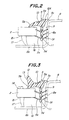
- the upper segment 5 includes a main body 5a which is provided with a first lip section 5b to be engaged with the outer surface of a windshield plate 2, a second lip section 5c to be engaged with the outer surface of the vehicle body panel 8, and a leg section 5d to be inserted into a gap 9 between the edge of the windshield plate 2 and a stepped shoulder portion 8a of the body panel 8.
- the leg section 5d has fins 5e, 5f on its both sides, which are to be engaged with the periphery of the windshield plate 2 and the shoulder portion 8a, respectively, so as to prevent undesirable withdrawal of the leg section 5d out of the gap 9.
- the upper segment 5 has an ornamental film 10 and core elements 11 arranged in the main body 5a and the leg section 5d, respectively.
- the cross-section of the upper segment 5 is common to the side segments 6, and will thus be referred to as a "common cross-section".
- the side segment 6 has a basic cross-sectional portion with the above-mentioned common cross-section of the upper segment 5, as well as an "additional cross-sectional portion" in the form of a ridge 12 on the first lip section 5b.
- the ridge 12 defines a channel or weir 13 extending along a side edge of the windshield plate 2, whereby rain water 14 on the windshield plate 2 can be guided along the ridge 12, and prevented from flowing onto the side windows 3 across the side segment 6 and the neighboring pillar of the vehicle body 1 to disturb the driver's sight through the side windows 3.
- the upper segment 5 without the ridge 12 on the first lip section 5b has a smooth outer surface, and thus serves to realize a so-called flush outer surface along the upper edge of the windshield plate 2.
- the corner segment 7 for connecting the upper and side segments 5, 6 into an integral component has a cross-section which gradually changes from that of the upper segment 5 to that of the side segment 6.
- the side segment 6 need not be provided with the ridge, while the upper segment 5 may be provided with a ridge 12A which is arranged on the second lip section 5c adjacent to the rear edge of the roof panel 8, as shown by imaginary line in Fig. 2.
- a ridge 12A serves to prevent rain water on the roof panel 8 from flowing across the molding member 4 and onto the rear window.
- the windshield plate 2 is shown in Figs. 2 and 3 as having a printed opaque layer 15 on the rear surface of its periphery, and being mounted along the periphery on a flange portion 8b of the body panel 8 with an adhesive material 16 and a dam rubber 17 arranged therebetween, in a conventional manner.
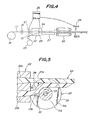
- Fig. 4 shows the schematic diagram of a production line, which may be used to continuously manufacture the above-mentioned molding member 4 in accordance with the present invention.
- the production line includes an uncoiler 18 and an associated pinch roller 19 for feeding the core element 11, which may be of a material with a low elongation, such as a metal strip, polyester-based resin sheet or a strand of glass- or carbon-fibers.
- the pinch roller 19 may be replaced by a roll forming device.
- the production line further includes another uncoiler 20 for feeding the ornamental film 10 with an excellent weatherability.
- the ornamental film 10 and the core element 11 are preferably applied with appropriate adhesive material.
- the feeding length of the core element 11 is detected by a detector 21, such as a rotary encoder.
- the ornamental film 10 and the core element 11 are fed to an extrusion die head 22 connected to an extruder, not shown.
- the extruder is adapted to heat a thermoplastic resin (e.g. PVC resin) to a temperature higher than its softening temperature, which is then fed to the die head 22 in a molten state.
- a thermoplastic resin e.g. PVC resin
- the die head 22 has a pair of orifices 22a, 22b which are arranged spaced from, but preferably close to each other (Fig. 9).
- the orifice 22a has a cross-section corresponding to that of the basic, common cross-sectional portion of the upper and side segments 5, 6, and will be referred to as a "common orifice”.
- the orifice 22b in turn, has a cross-section corresponding to that of the additional cross-sectional portion or the ridge 12 of the side segment 6, and will be referred to as an "additional orifice".
- the molten resin fed from the extruder is extruded, together with the ornamental film 10 and the core element 11, from the common orifice 22a and the additional orifice 22b of the die head 22, into extruded bodies 23a, 23b.
- These extruded bodies 23a, 23b are either caused to adhere with each other, or maintained spaced from each other, immediately after the extrusion, in accordance with the feeding length of the core element 11, thereby to form a desired continuous rod-like body 24.
- a guide device 25 is arranged adjacent to, and on the discharge side of the die head 22, and is controlled by a controller 26 which is connected to the detector 21.
- the guide device 25 includes a reciprocably rotatable guide wheel 30, which is formed in its outer periphery with a guide groove 31a for guiding the extruded body 22a corresponding to the common cross-sectional portion of the upper and side segments 5, 6, and also with a guide groove 31b for guiding the extruded body 22b corresponding to the additional cross-sectional portion or the ridge 12 of the side segment 6.
- the guide device 25 further includes a cutter 32 which extends from the bottom of the groove 31b as far as the periphery of the guide wheel 30, and which is adapted to cut away the extruded body 23b corresponding to the additional cross-sectional portion 12 perpendicularly to its longitudinal direction whenever necessary, as well as a drive shaft 33 connected to a reversible servomotor (not shown) which is controlled by the controller 26.
- a cutter 32 which extends from the bottom of the groove 31b as far as the periphery of the guide wheel 30, and which is adapted to cut away the extruded body 23b corresponding to the additional cross-sectional portion 12 perpendicularly to its longitudinal direction whenever necessary, as well as a drive shaft 33 connected to a reversible servomotor (not shown) which is controlled by the controller 26.
- the extrusion of the resin is carried out with the cutter 32 of the guide device 25 in abutment with the lower edge of the additional orifice 22b such that the extruded body 23b corresponding to the additional cross-sectional portion 12 of the side segment 6 is guided by the cutter 32 and the guide groove 31b so as to be brought into contact with, and adhesion to the extruded body 23a corresponding to the common cross-sectional portion.
- This serves to form a side segment 6 of the molding member 4.
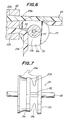
- the servomotor is actuated to drive the shaft 33 at a predetermined angular speed and displace the cutter 32. By this, the cutter 32 is gradually forced into the extruded body 23b to form the corner segment 7.
- the servomotor Upon a subsequent detection of the feeding length l2 of the core element 11, or of the completion of the formation of the corner segment 7, the servomotor is stopped by the controller 26. On this occasion, as shown in Fig. 6, the cutter 32 has already been brought into abutment with the upper edge of the additional orifice 22b, after completely cutting away the extruded body 23b corresponding to the additional cross-sectional portion 12. The extruded body 23b is thus guided by the cutter 32 and the guide groove 31b as being maintained spaced from the extruded body 23a, thereby permitting formation of the upper segment 5 with the common cross-sectional portion only.
- the servomotor is actuated to drive the shaft 33 in a reverse direction and displace the cutter 32 back to its initial position shown in Fig. 5 into abutment with the lower edge of the additional orifice 22b, after cutting away the extruded body 23b.
- the extruded body 23b corresponding to the additional cross-sectional portion 12 of the side segment 6 is guided by the cutter 32 and the guide groove 31b so as to be brought into contact with and adhesion to the extruded body 23a to form another side segment 6.
- each molding member 4 is obtained by cutting the continuous rod-like body 24 by means of the cutting device 29.
- the resin material to be extruded from the common orifice 22a and the additional orifice 22b may be same with, or different from each other, e.g. in color, transparency and/or hardness.
- the extrusion die head 22 is associated with two extruders and is preferably fed with mutually compatible resins. If the mutually compatible resins do not still exhibit a good adhesion to each other, or when resins having poor compatibility with each other are used the extruded body 22b for the additional cross-sectional portion 12 may be applied with an adhesive material by a roll coater 34 as shown in Fig. 5 immediately after it has been extruded from the orifice 22b.
- these grooves are preferably composed of stainless steel, ceramics, appropriate synthetic resin or the like, having a smooth outer surface and exhibiting a poor adhesion to the extruded bodies 23a, 23b.
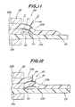
- FIGs. 11 to 15 another embodiment of the guide device arranged adjacent to the extrusion die head 22 wherein the common orifice 22a is situated below the additional orifice 22b.
- the guide device according to the present embodiment designated as a whole by reference numeral 40, includes a cutter element 41 on the upper side, and a support element 42 on the lower side, which are vertically spaced from each other by a predetermined distance.
- the cutter element 41 and the support element 42 are adapted to swing about respective horizontal axes near their front ends, such that their rear ends adjacent to the die head 22 are reciprocably movable in a vertical direction.
- the cutter element 41 has a cross-section which conforms with the outer contour of the extruded body 23b or of the additional cross-sectional portion 12 of the molding member 4, and is provided with brackets 43a-43d on both sides of the front and rear ends, as well as a stopper 44 formed thereon.
- the support element 42 has a cross-section which conforms with the bottom of the extruded body 23b, and is provided with brackets 45a-45d on both sides of the front and rear ends.
- the brackets 43a-43d of the cutter element 41 are connected to the brackets 45a-45d of the support element 42 by link elements 46a-46d, respectively, such that the cutter element 41 and the support element 42 are jointly moved maintaining a constant space therebetween.
- the link elements 46c and 46d are connected by a bifurcated arm 47 to a threaded drive shaft 48.
- the drive shaft 48 is connected to a servomotor (not shown) which is controlled by a controller in accordance with the feeding length of the core element 11 as in the previous embodiment.
- the rear end of the cutter element 41 and the front end surface of the die head 22 each has a radius of curvature which conforms to the trajectory of the rear end of the cutter element 41.
- the support element 42 may be constructed in the same manner, or may alternatively be spaced a slight distance from the additional orifice 22b in the die head 22.
- the support element 42 has a width which gradually decreases forwardly from its rear end adjacent to the die head 22.
- the extruded body 23b corresponding to the additional cross-sectional portion 12 can be positively supported by the support element 42, and accurately guided onto the desired location of the extruded body 23a which, in turn, corresponds to the common cross-sectional portion of the molding member 4.
- the support element 42 has a smooth sliding surface for the extruded body 23b, to reduce the sliding resistance and avoid an undesirable deformation of the extruded body 23b.
- the extruded body 23b is caused to adhere to the extruded body 23a in the operational mode shown in Fig. 11. Thereafter, the drive shaft 48 is rotated by the servomotor to lower the rear ends of the cutter element 41 and the support element 42 so that the extruded body 23b for the additional cross-sectional portion 12 is cut by the cutter element 41. On this occasion, the extruded body 23b comes into abutment with the stopper 44, and is thereby deflected toward one side of the device 40 and then vertically downwardly by the gravity.
- the extruded body 23b is maintained out of contact with the extruded body 23a to form the upper segment 5 of the molding member 4, and may be collected into a receptacle to be used once again, if desired.
- the guide device 40 may be associated with a roll coater 34 as shown by an imaginary line in Fig. 11.
- the region of the extruded body 22b to be adhered to the extruded body 22a can be guided vertically downwardly by the gravity into contact with the extruded body 23a, while the region of the extruded body 22b to be prevented from adhesion to the extruded body 22a has to be guided by the guide device 40.
- the common orifice 22a and the additional orifice 22b may be spaced from each other not only in the vertical direction, but also in the horizontal direction.
- the operation of the production line may be controlled in accordance, not only with the feeding length of the core element 11, but also with the extruded length or hauling length of the rod-like body 24.
- the die head 22 may have an inner gate for allowing or interrupting extrusion of the resin from the additional orifice 22b.
- the present invention thus allows manufacture of various elongate articles, including molding members, having an excellent appearance with a smooth outer surface throughout the entire length, and without significant connection lines between different segments, as well as a remarkable reduction in the manufacturing cost.
Landscapes
- Engineering & Computer Science (AREA)
- Mechanical Engineering (AREA)
- Manufacturing & Machinery (AREA)
- Extrusion Moulding Of Plastics Or The Like (AREA)
Priority Applications (4)
| Application Number | Priority Date | Filing Date | Title |
|---|---|---|---|
| DE68927737T DE68927737T2 (de) | 1989-09-26 | 1989-09-26 | Verfahren und Vorrichtung zur Herstellung von länglichen Gegenständen |
| AU42311/89A AU618406B2 (en) | 1989-09-26 | 1989-09-26 | Method of, and apparatus for manufacturing elongate plastic articles |
| EP89309760A EP0419738B1 (fr) | 1989-09-26 | 1989-09-26 | Procédé et dispositif pour la fabrication d'articles allongés |
| CA000613721A CA1322645C (fr) | 1989-09-26 | 1989-09-27 | Methode et appariel de fabrication d'articles de plastique de forme allongee |
Applications Claiming Priority (2)
| Application Number | Priority Date | Filing Date | Title |
|---|---|---|---|
| EP89309760A EP0419738B1 (fr) | 1989-09-26 | 1989-09-26 | Procédé et dispositif pour la fabrication d'articles allongés |
| CA000613721A CA1322645C (fr) | 1989-09-26 | 1989-09-27 | Methode et appariel de fabrication d'articles de plastique de forme allongee |
Publications (2)
| Publication Number | Publication Date |
|---|---|
| EP0419738A1 true EP0419738A1 (fr) | 1991-04-03 |
| EP0419738B1 EP0419738B1 (fr) | 1997-01-29 |
Family
ID=25673111
Family Applications (1)
| Application Number | Title | Priority Date | Filing Date |
|---|---|---|---|
| EP89309760A Expired - Lifetime EP0419738B1 (fr) | 1989-09-26 | 1989-09-26 | Procédé et dispositif pour la fabrication d'articles allongés |
Country Status (3)
| Country | Link |
|---|---|
| EP (1) | EP0419738B1 (fr) |
| AU (1) | AU618406B2 (fr) |
| CA (1) | CA1322645C (fr) |
Cited By (1)
| Publication number | Priority date | Publication date | Assignee | Title |
|---|---|---|---|---|
| EP0719637A3 (fr) * | 1994-12-27 | 1996-11-27 | Toyoda Gosei Kk | Procédé pour décorer un article en caoutchouc extrudé |
Citations (6)
| Publication number | Priority date | Publication date | Assignee | Title |
|---|---|---|---|---|
| EP0111458A2 (fr) * | 1982-12-10 | 1984-06-20 | S.A.I.A.G. S.p.A. | Procédé pour l'extrusion en continu d'un article extrudé, en particulier de bandes d'étancheité pour véhicules et l'article extrudé ainsi obtenu |
| FR2543486A1 (fr) * | 1983-04-01 | 1984-10-05 | Saiag Spa | Procede et dispositif pour extruder en continu un profil, en particulier une bande d'etancheite pour carrosseries de vehicules automobiles |
| EP0158919A2 (fr) * | 1984-04-14 | 1985-10-23 | BASF Aktiengesellschaft | Procédé et dispositif pour produire des corps creux moulés par soufflage en matières synthétiques |
| FR2579927A1 (fr) * | 1985-04-03 | 1986-10-10 | Saiag Spa | |
| DE3744576A1 (de) * | 1987-03-25 | 1988-10-06 | Toyoda Gosei Kk | Verfahren zum herstellen eines dichtungsprofilstreifens |
| GB2206839A (en) * | 1987-07-14 | 1989-01-18 | Ages Spa | Automatic variation of extrusion cross section independence on length thereof |
Family Cites Families (2)
| Publication number | Priority date | Publication date | Assignee | Title |
|---|---|---|---|---|
| US5112547A (en) * | 1989-08-07 | 1992-05-12 | Hashimoto Forming Industry Co., Ltd. | Method of making an elongate article |
| DE68911306T2 (de) * | 1989-10-18 | 1994-03-24 | Hashimoto Forming Kogyo Co | Fensterprofilstücke für Kraftfahrzeuge und Herstellungsverfahren dafür. |
-
1989
- 1989-09-26 EP EP89309760A patent/EP0419738B1/fr not_active Expired - Lifetime
- 1989-09-26 AU AU42311/89A patent/AU618406B2/en not_active Ceased
- 1989-09-27 CA CA000613721A patent/CA1322645C/fr not_active Expired - Fee Related
Patent Citations (6)
| Publication number | Priority date | Publication date | Assignee | Title |
|---|---|---|---|---|
| EP0111458A2 (fr) * | 1982-12-10 | 1984-06-20 | S.A.I.A.G. S.p.A. | Procédé pour l'extrusion en continu d'un article extrudé, en particulier de bandes d'étancheité pour véhicules et l'article extrudé ainsi obtenu |
| FR2543486A1 (fr) * | 1983-04-01 | 1984-10-05 | Saiag Spa | Procede et dispositif pour extruder en continu un profil, en particulier une bande d'etancheite pour carrosseries de vehicules automobiles |
| EP0158919A2 (fr) * | 1984-04-14 | 1985-10-23 | BASF Aktiengesellschaft | Procédé et dispositif pour produire des corps creux moulés par soufflage en matières synthétiques |
| FR2579927A1 (fr) * | 1985-04-03 | 1986-10-10 | Saiag Spa | |
| DE3744576A1 (de) * | 1987-03-25 | 1988-10-06 | Toyoda Gosei Kk | Verfahren zum herstellen eines dichtungsprofilstreifens |
| GB2206839A (en) * | 1987-07-14 | 1989-01-18 | Ages Spa | Automatic variation of extrusion cross section independence on length thereof |
Non-Patent Citations (4)
| Title |
|---|
| PATENT ABSTRACTS OF JAPAN, vol. 13, no. 489 (M-888)[3837], 7th November 1989; & JP-A-01 195 032 (HASHIMOTO FORMING IND. CO., LTD) 04-08-1989 * |
| PATENT ABSTRACTS OF JAPAN, vol. 13, no. 489 (M-888)[3837], 7th November 1989; & JP-A-01 195 033 (HASHIMOTO FORMING IND. CO., LTD) 04-08-1989 * |
| PATENT ABSTRACTS OF JAPAN, vol. 13, no. 506 (M-892)[3854], 14th November 1989; & JP-A-01 204 713 (HASHIMOTO FORMING IND. CO., LTD) 17-08-1989 * |
| PATENT ABSTRACTS OF JAPAN, vol. 13, no. 538 (M-900)[3886], 30th November 1989; & JP-A-01 221 218 (HASHIMOTO FORMING IND. CO., LTD) 04-09-1989 * |
Cited By (2)
| Publication number | Priority date | Publication date | Assignee | Title |
|---|---|---|---|---|
| EP0719637A3 (fr) * | 1994-12-27 | 1996-11-27 | Toyoda Gosei Kk | Procédé pour décorer un article en caoutchouc extrudé |
| US5753063A (en) * | 1994-12-27 | 1998-05-19 | Toyoda Gosei Co., Ltd. | Method of decorating rubber extruded product |
Also Published As
| Publication number | Publication date |
|---|---|
| EP0419738B1 (fr) | 1997-01-29 |
| CA1322645C (fr) | 1993-10-05 |
| AU4231189A (en) | 1991-04-11 |
| AU618406B2 (en) | 1991-12-19 |
Similar Documents
| Publication | Publication Date | Title |
|---|---|---|
| US5300346A (en) | Elongate plastic articles | |
| US5074610A (en) | Automobile molding member having improved weir structure | |
| EP0310262B1 (fr) | Joint d'étanchéité pour fenêtres et méthode pour sa fabrication | |
| EP0412217B1 (fr) | Procédé et dispositif pour la fabrication d'articles allongés | |
| US5070590A (en) | Method of manufacturing window moldings for vehicle | |
| US4765936A (en) | Method for the manufacture of a weather strip for motor vehicles | |
| EP0800909B1 (fr) | Procédé et extrudeuse pour poser une bande d'étanchéité sur un pare-brise | |
| US5104173A (en) | Window molding member for automobiles, and method of manufacturing the same | |
| EP0541824B1 (fr) | Moulure de fenetre pour vehicule et procede de production | |
| US5203946A (en) | Method of, and apparatus for manufacturing elongate plastic articles | |
| US5193875A (en) | Automobile windshield molding member and method of manufacturing the same | |
| US5310236A (en) | Molding member for automobile window plate | |
| EP0423407B1 (fr) | Eléments de moulure de fenêtre pour véhicules automobiles et procédé de fabrication des mêmes | |
| EP0419738B1 (fr) | Procédé et dispositif pour la fabrication d'articles allongés | |
| EP0818299B1 (fr) | Element composite allonge dont la section transversale varie longitudinalement, procede et appareil pour sa fabrication | |
| JPH06459B2 (ja) | ウインドモールディングおよびその製造方法 | |
| JPH0613186B2 (ja) | ウインドウモールディングの製造方法 | |
| EP0805013B1 (fr) | Appareil pour former une bande d'étanchéité extrudée | |
| JPH08230011A (ja) | 合成樹脂枠体付きガラス板の製造方法 | |
| DE68927737T2 (de) | Verfahren und Vorrichtung zur Herstellung von länglichen Gegenständen | |
| JP3310126B2 (ja) | 枠体付きパネルの製造法 | |
| JP3605857B2 (ja) | リップを有する長尺トリム材、その製造方法および製造装置 | |
| JPH01244836A (ja) | 車両用樹脂成形品の製造方法 |
Legal Events
| Date | Code | Title | Description |
|---|---|---|---|
| PUAI | Public reference made under article 153(3) epc to a published international application that has entered the european phase |
Free format text: ORIGINAL CODE: 0009012 |
|
| AK | Designated contracting states |
Kind code of ref document: A1 Designated state(s): DE FR GB IT |
|
| 17P | Request for examination filed |
Effective date: 19910711 |
|
| 17Q | First examination report despatched |
Effective date: 19930211 |
|
| GRAG | Despatch of communication of intention to grant |
Free format text: ORIGINAL CODE: EPIDOS AGRA |
|
| GRAH | Despatch of communication of intention to grant a patent |
Free format text: ORIGINAL CODE: EPIDOS IGRA |
|
| GRAH | Despatch of communication of intention to grant a patent |
Free format text: ORIGINAL CODE: EPIDOS IGRA |
|
| GRAA | (expected) grant |
Free format text: ORIGINAL CODE: 0009210 |
|
| AK | Designated contracting states |
Kind code of ref document: B1 Designated state(s): DE FR GB IT |
|
| ITF | It: translation for a ep patent filed | ||
| REF | Corresponds to: |
Ref document number: 68927737 Country of ref document: DE Date of ref document: 19970313 |
|
| ET | Fr: translation filed | ||
| PLBE | No opposition filed within time limit |
Free format text: ORIGINAL CODE: 0009261 |
|
| STAA | Information on the status of an ep patent application or granted ep patent |
Free format text: STATUS: NO OPPOSITION FILED WITHIN TIME LIMIT |
|
| 26N | No opposition filed | ||
| REG | Reference to a national code |
Ref country code: GB Ref legal event code: IF02 |
|
| PGFP | Annual fee paid to national office [announced via postgrant information from national office to epo] |
Ref country code: IT Payment date: 20080926 Year of fee payment: 20 Ref country code: FR Payment date: 20080915 Year of fee payment: 20 |
|
| PGFP | Annual fee paid to national office [announced via postgrant information from national office to epo] |
Ref country code: DE Payment date: 20081002 Year of fee payment: 20 |
|
| PGFP | Annual fee paid to national office [announced via postgrant information from national office to epo] |
Ref country code: GB Payment date: 20081001 Year of fee payment: 20 |
|
| REG | Reference to a national code |
Ref country code: GB Ref legal event code: PE20 Expiry date: 20090925 |
|
| PG25 | Lapsed in a contracting state [announced via postgrant information from national office to epo] |
Ref country code: GB Free format text: LAPSE BECAUSE OF EXPIRATION OF PROTECTION Effective date: 20090925 |