EP0419983B2 - Tête d'extrusion pour la fabrication de produits extrudés à couches multiples - Google Patents
Tête d'extrusion pour la fabrication de produits extrudés à couches multiples Download PDFInfo
- Publication number
- EP0419983B2 EP0419983B2 EP90117807A EP90117807A EP0419983B2 EP 0419983 B2 EP0419983 B2 EP 0419983B2 EP 90117807 A EP90117807 A EP 90117807A EP 90117807 A EP90117807 A EP 90117807A EP 0419983 B2 EP0419983 B2 EP 0419983B2
- Authority
- EP
- European Patent Office
- Prior art keywords
- disk
- extruder head
- head according
- sections
- duct sections
- Prior art date
- Legal status (The legal status is an assumption and is not a legal conclusion. Google has not performed a legal analysis and makes no representation as to the accuracy of the status listed.)
- Expired - Lifetime
Links
- 238000001125 extrusion Methods 0.000 title claims abstract description 28
- 230000002093 peripheral effect Effects 0.000 claims 1
- 238000006243 chemical reaction Methods 0.000 abstract 1
- 239000000463 material Substances 0.000 description 4
- 238000000576 coating method Methods 0.000 description 1
- 238000010276 construction Methods 0.000 description 1
- 239000000110 cooling liquid Substances 0.000 description 1
- 230000001419 dependent effect Effects 0.000 description 1
- 238000004519 manufacturing process Methods 0.000 description 1
- 230000007704 transition Effects 0.000 description 1
- 238000011144 upstream manufacturing Methods 0.000 description 1
Images
Classifications
-
- B—PERFORMING OPERATIONS; TRANSPORTING
- B29—WORKING OF PLASTICS; WORKING OF SUBSTANCES IN A PLASTIC STATE IN GENERAL
- B29C—SHAPING OR JOINING OF PLASTICS; SHAPING OF MATERIAL IN A PLASTIC STATE, NOT OTHERWISE PROVIDED FOR; AFTER-TREATMENT OF THE SHAPED PRODUCTS, e.g. REPAIRING
- B29C48/00—Extrusion moulding, i.e. expressing the moulding material through a die or nozzle which imparts the desired form; Apparatus therefor
- B29C48/25—Component parts, details or accessories; Auxiliary operations
- B29C48/36—Means for plasticising or homogenising the moulding material or forcing it through the nozzle or die
- B29C48/50—Details of extruders
- B29C48/695—Flow dividers, e.g. breaker plates
- B29C48/70—Flow dividers, e.g. breaker plates comprising means for dividing, distributing and recombining melt flows
-
- B—PERFORMING OPERATIONS; TRANSPORTING
- B29—WORKING OF PLASTICS; WORKING OF SUBSTANCES IN A PLASTIC STATE IN GENERAL
- B29C—SHAPING OR JOINING OF PLASTICS; SHAPING OF MATERIAL IN A PLASTIC STATE, NOT OTHERWISE PROVIDED FOR; AFTER-TREATMENT OF THE SHAPED PRODUCTS, e.g. REPAIRING
- B29C48/00—Extrusion moulding, i.e. expressing the moulding material through a die or nozzle which imparts the desired form; Apparatus therefor
- B29C48/03—Extrusion moulding, i.e. expressing the moulding material through a die or nozzle which imparts the desired form; Apparatus therefor characterised by the shape of the extruded material at extrusion
- B29C48/09—Articles with cross-sections having partially or fully enclosed cavities, e.g. pipes or channels
-
- B—PERFORMING OPERATIONS; TRANSPORTING
- B29—WORKING OF PLASTICS; WORKING OF SUBSTANCES IN A PLASTIC STATE IN GENERAL
- B29C—SHAPING OR JOINING OF PLASTICS; SHAPING OF MATERIAL IN A PLASTIC STATE, NOT OTHERWISE PROVIDED FOR; AFTER-TREATMENT OF THE SHAPED PRODUCTS, e.g. REPAIRING
- B29C48/00—Extrusion moulding, i.e. expressing the moulding material through a die or nozzle which imparts the desired form; Apparatus therefor
- B29C48/03—Extrusion moulding, i.e. expressing the moulding material through a die or nozzle which imparts the desired form; Apparatus therefor characterised by the shape of the extruded material at extrusion
- B29C48/09—Articles with cross-sections having partially or fully enclosed cavities, e.g. pipes or channels
- B29C48/10—Articles with cross-sections having partially or fully enclosed cavities, e.g. pipes or channels flexible, e.g. blown foils
-
- B—PERFORMING OPERATIONS; TRANSPORTING
- B29—WORKING OF PLASTICS; WORKING OF SUBSTANCES IN A PLASTIC STATE IN GENERAL
- B29C—SHAPING OR JOINING OF PLASTICS; SHAPING OF MATERIAL IN A PLASTIC STATE, NOT OTHERWISE PROVIDED FOR; AFTER-TREATMENT OF THE SHAPED PRODUCTS, e.g. REPAIRING
- B29C48/00—Extrusion moulding, i.e. expressing the moulding material through a die or nozzle which imparts the desired form; Apparatus therefor
- B29C48/16—Articles comprising two or more components, e.g. co-extruded layers
- B29C48/18—Articles comprising two or more components, e.g. co-extruded layers the components being layers
- B29C48/21—Articles comprising two or more components, e.g. co-extruded layers the components being layers the layers being joined at their surfaces
-
- B—PERFORMING OPERATIONS; TRANSPORTING
- B29—WORKING OF PLASTICS; WORKING OF SUBSTANCES IN A PLASTIC STATE IN GENERAL
- B29C—SHAPING OR JOINING OF PLASTICS; SHAPING OF MATERIAL IN A PLASTIC STATE, NOT OTHERWISE PROVIDED FOR; AFTER-TREATMENT OF THE SHAPED PRODUCTS, e.g. REPAIRING
- B29C48/00—Extrusion moulding, i.e. expressing the moulding material through a die or nozzle which imparts the desired form; Apparatus therefor
- B29C48/25—Component parts, details or accessories; Auxiliary operations
- B29C48/30—Extrusion nozzles or dies
- B29C48/32—Extrusion nozzles or dies with annular openings, e.g. for forming tubular articles
- B29C48/335—Multiple annular extrusion nozzles in coaxial arrangement, e.g. for making multi-layered tubular articles
- B29C48/336—Multiple annular extrusion nozzles in coaxial arrangement, e.g. for making multi-layered tubular articles the components merging one by one down streams in the die
- B29C48/3363—Multiple annular extrusion nozzles in coaxial arrangement, e.g. for making multi-layered tubular articles the components merging one by one down streams in the die using a layered die, e.g. stacked discs
-
- B—PERFORMING OPERATIONS; TRANSPORTING
- B29—WORKING OF PLASTICS; WORKING OF SUBSTANCES IN A PLASTIC STATE IN GENERAL
- B29C—SHAPING OR JOINING OF PLASTICS; SHAPING OF MATERIAL IN A PLASTIC STATE, NOT OTHERWISE PROVIDED FOR; AFTER-TREATMENT OF THE SHAPED PRODUCTS, e.g. REPAIRING
- B29C48/00—Extrusion moulding, i.e. expressing the moulding material through a die or nozzle which imparts the desired form; Apparatus therefor
- B29C48/25—Component parts, details or accessories; Auxiliary operations
- B29C48/30—Extrusion nozzles or dies
- B29C48/32—Extrusion nozzles or dies with annular openings, e.g. for forming tubular articles
- B29C48/34—Cross-head annular extrusion nozzles, i.e. for simultaneously receiving moulding material and the preform to be coated
-
- B—PERFORMING OPERATIONS; TRANSPORTING
- B29—WORKING OF PLASTICS; WORKING OF SUBSTANCES IN A PLASTIC STATE IN GENERAL
- B29C—SHAPING OR JOINING OF PLASTICS; SHAPING OF MATERIAL IN A PLASTIC STATE, NOT OTHERWISE PROVIDED FOR; AFTER-TREATMENT OF THE SHAPED PRODUCTS, e.g. REPAIRING
- B29C48/00—Extrusion moulding, i.e. expressing the moulding material through a die or nozzle which imparts the desired form; Apparatus therefor
- B29C48/03—Extrusion moulding, i.e. expressing the moulding material through a die or nozzle which imparts the desired form; Apparatus therefor characterised by the shape of the extruded material at extrusion
- B29C48/12—Articles with an irregular circumference when viewed in cross-section, e.g. window profiles
-
- B—PERFORMING OPERATIONS; TRANSPORTING
- B29—WORKING OF PLASTICS; WORKING OF SUBSTANCES IN A PLASTIC STATE IN GENERAL
- B29C—SHAPING OR JOINING OF PLASTICS; SHAPING OF MATERIAL IN A PLASTIC STATE, NOT OTHERWISE PROVIDED FOR; AFTER-TREATMENT OF THE SHAPED PRODUCTS, e.g. REPAIRING
- B29C48/00—Extrusion moulding, i.e. expressing the moulding material through a die or nozzle which imparts the desired form; Apparatus therefor
- B29C48/16—Articles comprising two or more components, e.g. co-extruded layers
- B29C48/18—Articles comprising two or more components, e.g. co-extruded layers the components being layers
- B29C48/19—Articles comprising two or more components, e.g. co-extruded layers the components being layers the layers being joined at their edges
-
- B—PERFORMING OPERATIONS; TRANSPORTING
- B29—WORKING OF PLASTICS; WORKING OF SUBSTANCES IN A PLASTIC STATE IN GENERAL
- B29C—SHAPING OR JOINING OF PLASTICS; SHAPING OF MATERIAL IN A PLASTIC STATE, NOT OTHERWISE PROVIDED FOR; AFTER-TREATMENT OF THE SHAPED PRODUCTS, e.g. REPAIRING
- B29C48/00—Extrusion moulding, i.e. expressing the moulding material through a die or nozzle which imparts the desired form; Apparatus therefor
- B29C48/25—Component parts, details or accessories; Auxiliary operations
- B29C48/30—Extrusion nozzles or dies
- B29C48/32—Extrusion nozzles or dies with annular openings, e.g. for forming tubular articles
- B29C48/335—Multiple annular extrusion nozzles in coaxial arrangement, e.g. for making multi-layered tubular articles
Definitions
- the present invention relates to an extrusion head for producing multi-layer profiles, in particular hollow profiles.
- an extrusion head for the production of two-layer profiles, in particular hollow profiles, with an element forming an annular nozzle, which lies in a plane perpendicular to the direction of extrusion is known (obvious prior use Reifen Reifenberger GmbH & Co. Maschinenfabrik, D-53839 Troisdorf).
- the ring nozzle is formed by a feed element paired with a tightly fitting insert ring having an aperture opening.
- the feed element has a passage which is coaxial with the aperture opening and is provided with an inlet connection formed on its circumference. This is connected to the ring nozzle via a multi-branched feed channel.
- extrusion heads are described, for example, in GB-A-1 125 742, they are made up of a plurality of funnel-shaped elements arranged one inside the other at a radial distance, the inner wall of one element tapering toward the nozzle opening with the outer wall of the element arranged therein Form the jacket gap. All of these elements end at their narrowest point in an annular nozzle which is arranged in a plane substantially perpendicular to the direction of extrusion.
- extrusion heads are relatively expensive.
- the thickness of the individual layer to be extruded is given by the difference between the inside diameter at the end of one element and the outside diameter at the end of the element arranged therein.
- a change in the thickness of the layer to be extruded can only be achieved to a limited extent by axially adjusting the funnel-shaped elements with respect to one another.
- special precautions are required to extrude coatings directly onto a basic extrudate using the known extrusion heads.
- the known extrusion heads it is only possible to extrude a comparatively small number of layers at the same time.
- the individual elements are easily damaged during assembly work; in addition, the assembly is cumbersome and time-consuming.
- the basic profile and the layers above are produced in individual extruders, the hollow profile has to be cooled and heated between the individual extrusions.
- the invention is based on the problem of developing the extrusion head of the type described at the outset in such a way that, with a simple structure, a plurality of layers can be applied.
- the proposed extrusion head fulfills this purpose by having the features described in claim 1.
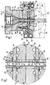
- the main extrusion head consists of a die part 12 which is penetrated by a hollow mandrel part 13, which extends beyond the end of the die part 12.
- the existing between the inside of the die part 12 and the outside of the mandrel part 13, conical and tapered in terms of "wall thickness" jacket gap 14 is supplied by the upstream screw press in the direction of arrow 15 plasticized plastic material, which then the die part 12 as the projecting section 18 of Hollow profile surrounding the mandrel part 13 in the present case as a tube with an outer diameter that corresponds to the inner diameter of the outlet opening 17 of the die part, while its inner diameter corresponds to the outer diameter of the cylindrical end section 18 of the mandrel part 13.
- the cavity 16 in the mandrel part 13 can serve to guide a cooling liquid.
- the extrusion head 11 Immediately to the main extrusion head 10 is an inventive extrusion head 11, with which several layers of further plastic materials are directly extruded onto the outside of the extrudate of the main extrusion head 10.
- the extrusion head 11 has a plurality of feed elements 20, 21, 22, 23 (see also FIG. 2).
- Each of the feed elements 20-23 is paired with a closely fitting disc 24, 25, here the feed elements 20, 21 are paired with the disc 24 and the feed elements 22, 23 are paired with the disc 25.
- the feed element 20 has a central passage 26, the inside diameter of which corresponds exactly to the inside diameter of the outlet opening 17 and is designated d 1 in FIG. 2.
- d 1 the inside diameter of the outlet opening 17
- centering surfaces are formed both on the feed element 20 and on the end face of the die part 12, for example on the feed element 20 an annular rib 27 which engages in a shoulder 29 on the end face.
- a circular recess 30 or 31 is formed on their sides facing each other, the depth of which is less than half the thickness of the disk 24 clamped between the feed elements 20 and 21. to center the circular disk 24, which has a central aperture 32 (FIG. 2), coaxially with respect to the passage 20.
- the recess 31 serves to center the feed element 21, which also has a central passage 33 (FIG. 2), with respect to the disk 24 and thus also with respect to the feed element 20.
- the feed elements 22, 23, which are only indicated with their outlines in FIG. 1, are mounted on the feed element 21 with the intermediate scraper 25. It remains to be added that the feed element 21 is clamped to the feed element 20 by means of bolts 28 '.
- Each of the feed elements 20-23 has an inlet connection on its circumference, only the inlet connections 34, 35 of the feed elements 20 and 21 being shown in solid lines in FIG. 1.
- the outlet of a further extruder, not shown, is connected to each of these inlet connections and feeds a further, plasticized plastic material to the relevant inlet connection.
- the feed elements can be arranged with inlet connections offset in the circumferential direction. Accordingly, the connecting pieces of the auxiliary extruders supplying the feed elements can be offset from one another.
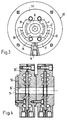
- two channel sections 36, 37 extend from the inner end of the inlet connection 24 in opposite directions, at the ends of which two further channel sections 38, 39 and 40, 41 each connect in opposite directions .
- channel sections 36-41 have the shape of an arcuate groove with (see FIG. 1) essentially a semicircular cross section, the passage cross section of the channel sections 36,37 being larger than that of the channel sections 38-41.
- the channel sections 38-41 open out at locations which have a circumferential distance of 90 ° from one another into a self-contained circumferential groove 42, which over its entire circumference has an annular gap 43 (between the flat disk 24 and the side of the feed element 20 facing it) ( Fig. 1,2) is connected.
- This annular gap 43 opens into the transition point between the passage 26 of the feed element 20 and the diaphragm opening 32 of the disk 24.
- This diaphragm opening 32 has an inner diameter denoted by d 2 in FIG d 1 resulting extrudate extruded layer is greater than d 1 .
- the aperture 32 thus also serves as a calibration opening.
- the side of the feed element 21 facing the disk 24 carries a feed channel starting from the inlet connection 35, which has the same design as the feed channel of the feed element 20 described with reference to FIG. 3, which is why a description of the same is unnecessary at this point.
- the feed channel of the feed element 21 ends in an annular gap 44 (FIG. 2) which is open towards the passage 33.
- This passage 33 has an inner diameter denoted by d 3 , which is greater than d 2 by twice the layer thickness of the material layer extruded through the feed element 21.
- the central passage in the feed element 22 is designated 45 and also has the diameter d 3 .
- the feed channel formed on the side of the feed element 22 facing the disk 25 is again of the same design as described with reference to FIG. 3. This in turn opens into an annular gap 47 formed with the flat side of the disk 25 and open to the passage 45 and to the aperture opening 46 of the disk 45, through which an additional layer is extruded onto the already existing two extruded layers.
- the aperture 46 therefore has an inner diameter denoted by d 4 , which is greater than d 3 by twice the layer thickness of the layer extruded through the annular gap 47.
- the feed element 23 carries on its side facing the disk 25 a feed channel which is of the same design as described with reference to FIG. 3. It opens into an annular gap 49 that is open toward the aperture 46 of the disk 25 and towards the passage 48 in the feed element 23.
- the passage 48 has an internal diameter denoted by d 5 , which is twice the layer thickness of the layer extruded through the annular gap 49 than d 4 .
- the extrusion head described not only has a very simple structure, but can also be converted with a minimum of effort for other dimensions of the layers to be extruded.
- all the feed elements, with the exception of their central passages, have the same dimensions. The same applies to the disks.
- FIG. 4 shows a longitudinal section through the extrusion head described in its design for extruding four plastic layers onto an already existing round profile, for example onto a plastic tube.
- the construction of the embodiment of FIG. 4 is identical to that of FIG. 1, with the exception that this does not directly connect to a main extrusion head, but instead is provided with a coaxial inlet aperture 50 with an aperture opening 51, the inside diameter of which is the same as the inside diameter of the central passage 26 'in the adjoining feed element 20'.
Landscapes
- Engineering & Computer Science (AREA)
- Mechanical Engineering (AREA)
- Manufacturing & Machinery (AREA)
- Extrusion Moulding Of Plastics Or The Like (AREA)
Claims (10)
- Tête d'extrusion pour la fabrication de profilés multicouches, en particulier de profilés creux, qui est destinée à être installée en aval d'une tête d'extrusion principale (10) pour un profilé de base et à déposer plusieurs couches sur la face extérieure du profilé de base, avec pour chaque couche une buse annulaire (43, 44, 47, 49) située dans un plan sensiblement perpendiculaire à la direction d'extrusion, et qui est formée par un élément d'alimentation (20, 21, 22, 23) associé par paire à un disque (24, 25) présentant une ouverture d'étranglement (32, 46) et appliqué de façon étanche, l'élément d'alimentation présentant un passage (26, 33, 45, 48) coaxial à l'ouverture d'étranglement (32, 46) et étant pourvu d'une tubulure d'admission (34, 35) réalisée à sa périphérie, et reliée à la buse annulaire (43, 44, 47, 49) par l'intermédiaire d'un canal d'amenée (36, 37, 38, 39, 40, 41, 42) à plusieurs ramifications ouvert en direction du disque, dans laquelle tubulure d'admission deux éléments d'alimentation (20, 21, 22, 23) disposés de part et d'autre d'un disque (24, 25) forment avec le disque (24, 25) deux buses annulaires (43, 44, 47, 49) de part et d'autre de celui-ci et les passages (26, 33, 45, 48) des éléments d'alimentation (20, 21, 22, 23) et l'ouverture d'étranglement (32, 46) du disque (24, 25) sont de grandeurs différentes pour former des couches situées l'une au-dessus de l'autre.
- Tête d'extrusion selon la revendication 1, caractérisée en ce que les deux éléments d'alimentation (20, 21; 22, 23) sont serrés l'un contre l'autre au moyen de vis (28') et serrent entre eux le disque (24; 25).
- Tête d'extrusion selon la revendication 1 ou 2, caractérisée en ce que le canal d'amenée présente deux tronçons de canal (36, 37) partant de la tubulure d'admission (34, 35), dans des directions opposées, des extrémités desquelles partent chaque fois deux autres tronçons de canal (38, 39; 40, 41), dans des directions opposées, qui débouchent à leur tour dans une fente annulaire (43, 44, 47, 49), entourant le passage (26, 33, 45, 48) de l'élément d'alimentation (20, 21, 22, 23), et qui forme la buse annulaire.
- Tête d'extrusion selon la revendication 3, caractérisée en ce que les autres tronçons de canal (38, 39; 40, 41) débouchent dans la fente annulaire (43, 44, 47, 49), suivant des espacements circonférentiels réguliers.
- Tête d'extrusion selon la revendication 2 ou 3, caractérisée en ce que les tronçons de canal (36 - 41) présentent un profil en forme d'arc de cercle, coaxial au passage (26, 33, 45, 48) de l'élément d'alimentation (20 - 23) .
- Tête d'extrusion selon l'une des revendications 3 à 5, caractérisée en ce que les tronçons de canal (36 - 41) présentent une section transversale sensiblement en forme de demi-cercle.
- Tête d'extrusion selon l'une des revendications 3 à 6, caractérisée en ce que les premiers tronçons de canal cités (36, 37) présentent une section transversale d'écoulement, supérieure à celle des autres tronçons de canal (38 - 41).
- Tête d'extrusion selon la revendication 2, caractérisée en ce que les faces des deux éléments d'alimentation (20, 21; 22, 23) situées à l'opposé du disque (24, 25), sont pourvues de surfaces de centrage (27, 29), de formes conjuguées, coaxiales au passage (26, 33, 45, 48).
- Tête d'extrusion selon la revendication 2, caractérisée en ce que le disque (24, 25) est circulaire et les deux éléments d'alimentation (20, 21; 22, 23) présentent, sur leur face tournée vers le disque (24, 25), une cavité circulaire (30, 31) dont le diamètre intérieur correspond au diamètre extérieur du disque (24, 25) et dont la profondeur est inférieure à la moitié de l'épaisseur du disque (24, 25).
- Tête d'extrusion selon l'une des revendications précédentes, caractérisée en ce qu'elle est reliée à la tête d'extrusion principale (10).
Priority Applications (1)
| Application Number | Priority Date | Filing Date | Title |
|---|---|---|---|
| AT90117807T ATE92839T1 (de) | 1989-09-26 | 1990-09-15 | Extrudierkopf zum herstellen mehrschichtiger extrudate. |
Applications Claiming Priority (2)
| Application Number | Priority Date | Filing Date | Title |
|---|---|---|---|
| CH348689 | 1989-09-26 | ||
| CH3486/89 | 1989-09-26 |
Publications (3)
| Publication Number | Publication Date |
|---|---|
| EP0419983A1 EP0419983A1 (fr) | 1991-04-03 |
| EP0419983B1 EP0419983B1 (fr) | 1993-08-11 |
| EP0419983B2 true EP0419983B2 (fr) | 1996-07-17 |
Family
ID=4257032
Family Applications (1)
| Application Number | Title | Priority Date | Filing Date |
|---|---|---|---|
| EP90117807A Expired - Lifetime EP0419983B2 (fr) | 1989-09-26 | 1990-09-15 | Tête d'extrusion pour la fabrication de produits extrudés à couches multiples |
Country Status (3)
| Country | Link |
|---|---|
| EP (1) | EP0419983B2 (fr) |
| AT (1) | ATE92839T1 (fr) |
| DE (1) | DE59002295D1 (fr) |
Families Citing this family (5)
| Publication number | Priority date | Publication date | Assignee | Title |
|---|---|---|---|---|
| DE4235101C2 (de) * | 1992-10-17 | 1994-11-10 | Krupp Bellaform Maschbau | Verfahren und Spritzkopf zum Herstellen und/oder Umhüllen von Strangprofilen |
| US5672303A (en) * | 1992-10-17 | 1997-09-30 | Bellaform Extrusionstechnik Gmbh | Process and extruding head for the manufacture and/or coating of extruding profiles |
| US6190152B1 (en) | 1996-08-26 | 2001-02-20 | Addex, Inc. | Regular division of molten extrusion flow |
| DE19835189C2 (de) | 1998-08-04 | 2001-02-08 | Unicor Rohrsysteme Gmbh | Vorrichtung zur kontinuierlichen Herstellung von nahtlosen Kunststoffrohren |
| US6343919B1 (en) * | 2000-02-28 | 2002-02-05 | Ricardo Pablo Rodriguez | Modular plastics extrusion die |
Family Cites Families (6)
| Publication number | Priority date | Publication date | Assignee | Title |
|---|---|---|---|---|
| CH315684A (it) * | 1952-10-08 | 1956-08-31 | Lavorazione Mat Plastiche Sas | Rivestimento protettivo per tubi metallici, procedimento per la sua fabbricazione ed apparecchio per l'attuazione di questo procedimento |
| US3417432A (en) * | 1965-08-27 | 1968-12-24 | Brockway Glass Co Inc | Apparatus for extruding composite blow molding parisons |
| FR1589770A (fr) * | 1968-10-21 | 1970-04-06 | ||
| DE2031890A1 (de) * | 1969-06-30 | 1971-01-28 | Joseph Lucas (Industries) Ltd . Birmingham (Großbritannien) | Verfahren zur Herstellung eines mehrwandigen Hohlkörpers |
| CH565031A5 (fr) * | 1972-09-22 | 1975-08-15 | Dynamit Nobel Ag | |
| US4806289A (en) * | 1987-01-16 | 1989-02-21 | The Dow Chemical Company | Method of making a hollow light pipe |
-
1990
- 1990-09-15 EP EP90117807A patent/EP0419983B2/fr not_active Expired - Lifetime
- 1990-09-15 DE DE9090117807T patent/DE59002295D1/de not_active Expired - Fee Related
- 1990-09-15 AT AT90117807T patent/ATE92839T1/de not_active IP Right Cessation
Also Published As
| Publication number | Publication date |
|---|---|
| DE59002295D1 (de) | 1993-09-16 |
| ATE92839T1 (de) | 1993-08-15 |
| EP0419983B1 (fr) | 1993-08-11 |
| EP0419983A1 (fr) | 1991-04-03 |
Similar Documents
| Publication | Publication Date | Title |
|---|---|---|
| EP1116569B1 (fr) | Tête d'extrusion | |
| EP0215337B1 (fr) | Tête d'extrusion | |
| DE60130122T2 (de) | Rohrförmige mehrschichtige folien sowie verfahren und vorrichtung zu ihrer herstellung | |
| EP0494273B1 (fr) | Tete d'accumulation pour machine de moulage par soufflage | |
| EP0249866B1 (fr) | Tête d'accumulation pour la fabrication de tuyaux souples coextrudés multicouches en matière plastique | |
| DE1276906B (de) | Spritzkopf | |
| DE2510127A1 (de) | Strangpresskopf zum herstellen eines aus zwei konzentrischen, mit ihren schweissnaehten zueinander versetzten schichten bestehenden hohlstranges aus thermoplastischem werkstoff | |
| DE19535749C1 (de) | Extrusionskopf zur Herstellung von schlauch- oder rohrförmigen Vorformlingen aus extrudierbarem Kunststoff | |
| EP0250828B1 (fr) | Installation d'extrusion pour le revêtement de produits cylindriques, en particulier un câble | |
| DE2522357B2 (de) | Blasextruder | |
| EP1055504A1 (fr) | Filière d'extrusion | |
| EP0419983B1 (fr) | Tête d'extrusion pour la fabrication de produits extrudés à couches multiples | |
| EP0349872A1 (fr) | Procédé et dispositif pour la fabrication de corps creux en matière thermoplastique | |
| DE1660169A1 (de) | Spinnduese und Verfahren zur Herstellung eines Spinnkanals einer Spinnduese | |
| DE19941160A1 (de) | Zylinder für einen Schneckenextruder mit Kanälen für ein Temperiermedium | |
| DE2006941A1 (en) | Plasticising extruder perforated disc | |
| EP3479993B1 (fr) | Distributeur annulaire pour une tête d'extrusion permettant de fabriquer une pièce moulée en forme tubulaire en matière thermoplastique | |
| DE4114609A1 (de) | Hochleistungsextruder mit konstanter gangzahl im einlauf- und auslaufbereich eines transferscherteiles | |
| EP1426163A2 (fr) | Tête d'extrusion d'un film tubulaire | |
| DE3921631C2 (fr) | ||
| DE4235101C2 (de) | Verfahren und Spritzkopf zum Herstellen und/oder Umhüllen von Strangprofilen | |
| AT392933B (de) | Wendelkopfverteiler fuer eine kunststoff-extrusionseinrichtung | |
| AT325800B (de) | Strangpressanlage zur herstellung mehrfarbiger kunststoffröhrchen | |
| DE2710565A1 (de) | Spritzwerkzeug zum extrudieren von hohlen rohrelementen aus kunststoff und mit den rohrelementen erzielter behaelter | |
| DE4135336A1 (de) | Verfahren zum strangpressen von hohlprofilen |
Legal Events
| Date | Code | Title | Description |
|---|---|---|---|
| PUAI | Public reference made under article 153(3) epc to a published international application that has entered the european phase |
Free format text: ORIGINAL CODE: 0009012 |
|
| AK | Designated contracting states |
Kind code of ref document: A1 Designated state(s): AT CH DE FR GB IT LI |
|
| 17P | Request for examination filed |
Effective date: 19910506 |
|
| 17Q | First examination report despatched |
Effective date: 19920522 |
|
| GRAA | (expected) grant |
Free format text: ORIGINAL CODE: 0009210 |
|
| ITF | It: translation for a ep patent filed | ||
| AK | Designated contracting states |
Kind code of ref document: B1 Designated state(s): AT CH DE FR GB IT LI |
|
| REF | Corresponds to: |
Ref document number: 92839 Country of ref document: AT Date of ref document: 19930815 Kind code of ref document: T |
|
| GBT | Gb: translation of ep patent filed (gb section 77(6)(a)/1977) |
Effective date: 19930811 |
|
| REF | Corresponds to: |
Ref document number: 59002295 Country of ref document: DE Date of ref document: 19930916 |
|
| ET | Fr: translation filed | ||
| PLBI | Opposition filed |
Free format text: ORIGINAL CODE: 0009260 |
|
| PLAB | Opposition data, opponent's data or that of the opponent's representative modified |
Free format text: ORIGINAL CODE: 0009299OPPO |
|
| 26 | Opposition filed |
Opponent name: REIFENHAEUSER GMBH & CO. MASCHINENFABRIK Effective date: 19940511 |
|
| R26 | Opposition filed (corrected) |
Opponent name: REIFENHAEUSER GMBH & CO. MASCHINENFABRIK Effective date: 19940510 |
|
| PLAW | Interlocutory decision in opposition |
Free format text: ORIGINAL CODE: EPIDOS IDOP |
|
| PUAH | Patent maintained in amended form |
Free format text: ORIGINAL CODE: 0009272 |
|
| STAA | Information on the status of an ep patent application or granted ep patent |
Free format text: STATUS: PATENT MAINTAINED AS AMENDED |
|
| ITF | It: translation for a ep patent filed | ||
| 27A | Patent maintained in amended form |
Effective date: 19960717 |
|
| AK | Designated contracting states |
Kind code of ref document: B2 Designated state(s): AT CH DE FR GB IT LI |
|
| REG | Reference to a national code |
Ref country code: CH Ref legal event code: AEN Free format text: AUFRECHTERHALTUNG DES PATENTES IN GEAENDERTER FORM |
|
| PGFP | Annual fee paid to national office [announced via postgrant information from national office to epo] |
Ref country code: GB Payment date: 19960816 Year of fee payment: 7 |
|
| PGFP | Annual fee paid to national office [announced via postgrant information from national office to epo] |
Ref country code: DE Payment date: 19960821 Year of fee payment: 7 Ref country code: AT Payment date: 19960821 Year of fee payment: 7 |
|
| PGFP | Annual fee paid to national office [announced via postgrant information from national office to epo] |
Ref country code: FR Payment date: 19960827 Year of fee payment: 7 |
|
| GBTA | Gb: translation of amended ep patent filed (gb section 77(6)(b)/1977) |
Effective date: 19960814 |
|
| PGFP | Annual fee paid to national office [announced via postgrant information from national office to epo] |
Ref country code: CH Payment date: 19960925 Year of fee payment: 7 |
|
| ET3 | Fr: translation filed ** decision concerning opposition | ||
| PG25 | Lapsed in a contracting state [announced via postgrant information from national office to epo] |
Ref country code: GB Free format text: LAPSE BECAUSE OF NON-PAYMENT OF DUE FEES Effective date: 19970915 Ref country code: AT Free format text: LAPSE BECAUSE OF NON-PAYMENT OF DUE FEES Effective date: 19970915 |
|
| PG25 | Lapsed in a contracting state [announced via postgrant information from national office to epo] |
Ref country code: LI Free format text: LAPSE BECAUSE OF NON-PAYMENT OF DUE FEES Effective date: 19970930 Ref country code: FR Free format text: THE PATENT HAS BEEN ANNULLED BY A DECISION OF A NATIONAL AUTHORITY Effective date: 19970930 Ref country code: CH Free format text: LAPSE BECAUSE OF NON-PAYMENT OF DUE FEES Effective date: 19970930 |
|
| GBPC | Gb: european patent ceased through non-payment of renewal fee |
Effective date: 19970915 |
|
| REG | Reference to a national code |
Ref country code: CH Ref legal event code: PL |
|
| PG25 | Lapsed in a contracting state [announced via postgrant information from national office to epo] |
Ref country code: DE Free format text: LAPSE BECAUSE OF NON-PAYMENT OF DUE FEES Effective date: 19980603 |
|
| REG | Reference to a national code |
Ref country code: FR Ref legal event code: ST |
|
| PG25 | Lapsed in a contracting state [announced via postgrant information from national office to epo] |
Ref country code: IT Free format text: LAPSE BECAUSE OF NON-PAYMENT OF DUE FEES;WARNING: LAPSES OF ITALIAN PATENTS WITH EFFECTIVE DATE BEFORE 2007 MAY HAVE OCCURRED AT ANY TIME BEFORE 2007. THE CORRECT EFFECTIVE DATE MAY BE DIFFERENT FROM THE ONE RECORDED. Effective date: 20050915 |