EP0420001B1 - Hachoir pour viande - Google Patents
Hachoir pour viande Download PDFInfo
- Publication number
- EP0420001B1 EP0420001B1 EP90117896A EP90117896A EP0420001B1 EP 0420001 B1 EP0420001 B1 EP 0420001B1 EP 90117896 A EP90117896 A EP 90117896A EP 90117896 A EP90117896 A EP 90117896A EP 0420001 B1 EP0420001 B1 EP 0420001B1
- Authority
- EP
- European Patent Office
- Prior art keywords
- retaining ring
- teeth
- cutting
- cutting knife
- approximately
- Prior art date
- Legal status (The legal status is an assumption and is not a legal conclusion. Google has not performed a legal analysis and makes no representation as to the accuracy of the status listed.)
- Expired - Lifetime
Links
- 235000013372 meat Nutrition 0.000 claims description 6
- 230000000712 assembly Effects 0.000 claims 1
- 238000000429 assembly Methods 0.000 claims 1
- 230000002093 peripheral effect Effects 0.000 claims 1
- 238000003860 storage Methods 0.000 description 5
- 101100390736 Danio rerio fign gene Proteins 0.000 description 3
- 101100390738 Mus musculus Fign gene Proteins 0.000 description 3
- 241000283690 Bos taurus Species 0.000 description 2
- 238000003801 milling Methods 0.000 description 2
- 230000006978 adaptation Effects 0.000 description 1
- 230000018109 developmental process Effects 0.000 description 1
- 230000002349 favourable effect Effects 0.000 description 1
- 238000010438 heat treatment Methods 0.000 description 1
- 238000004519 manufacturing process Methods 0.000 description 1
- 238000003307 slaughter Methods 0.000 description 1
- 230000036346 tooth eruption Effects 0.000 description 1
- 230000007704 transition Effects 0.000 description 1
- 238000011144 upstream manufacturing Methods 0.000 description 1
Images


Classifications
-
- B—PERFORMING OPERATIONS; TRANSPORTING
- B02—CRUSHING, PULVERISING, OR DISINTEGRATING; PREPARATORY TREATMENT OF GRAIN FOR MILLING
- B02C—CRUSHING, PULVERISING, OR DISINTEGRATING IN GENERAL; MILLING GRAIN
- B02C18/00—Disintegrating by knives or other cutting or tearing members which chop material into fragments
- B02C18/30—Mincing machines with perforated discs and feeding worms
- B02C18/301—Mincing machines with perforated discs and feeding worms with horizontal axis
- B02C18/304—Mincing machines with perforated discs and feeding worms with horizontal axis with several axially aligned knife-perforated disc units
-
- B—PERFORMING OPERATIONS; TRANSPORTING
- B02—CRUSHING, PULVERISING, OR DISINTEGRATING; PREPARATORY TREATMENT OF GRAIN FOR MILLING
- B02C—CRUSHING, PULVERISING, OR DISINTEGRATING IN GENERAL; MILLING GRAIN
- B02C18/00—Disintegrating by knives or other cutting or tearing members which chop material into fragments
- B02C18/30—Mincing machines with perforated discs and feeding worms
- B02C18/36—Knives or perforated discs
Definitions
- the invention relates to a shredding machine, in particular for meat and the like.
- a shredding machine in particular for meat and the like.
- Two cutting sets arranged one behind the other in the direction of throughput of the material to be cut, each consisting of a perforated disc and a rotating cutting knife
- a variety of radial ram teeth is equipped, the cutting knife body protruding into the baffle ring.
- the material to be sliced is usually fed to the machine via a hopper and, in the meat processing industry, it consists of relatively large chunks of meat, braids, rinds and other parts of the slaughter cattle. In particular due to the fat content, these parts tend to adhere to the walls of their passage and it is therefore necessary to provide suitable means for further transport. Sometimes the weight of the mass in the funnel is sufficient.
- Another problem is that the material to be crushed arrives first. Cutting set must be transported through the gaps between the arms of the cutting knife to the perforated disc, because, seen in the direction of flow, the cutting knife is upstream of the perforated disc of the relevant cutting set. Due to the high speed of the cutting knife and the adherence of the material to be cut, it tends to rotate in the area of the cutting knife. This reduces the cutting performance and also brings about undesirable local heating.
- a device for meat cutting in which a substantially cylindrical rotor with cutting edges formed by circumferential grooves rotates in a likewise substantially hollow cylindrical stator with cutting teeth formed by grooves.
- the edges of the rotor and the slots of the stator take on a cutting function and a cutting function.
- the object of the invention is to develop the comminution machine of the type mentioned at the outset in such a way that the passage of the material to be cut through the machine is improved, in particular in the region of the first cutting set.
- the shredding machine is designed in accordance with the preamble of claim 1 in accordance with the characterizing part of this claim.
- a baffle ring with a large number of jam teeth
- the latter is gripped by the rotating cutting knife.
- Cut material seen in the direction of rotation opposes a considerable resistance, so that turning is at least reduced, but preferably completely switched off.
- the material to be cut to which a certain feed pressure is exerted from the inside, has to move on to the perforated disc and it is then gripped there by the cutting edges of the cutting knife.
- the pre-shredded material is also prevented from rotating between the two cutting sets and a jam is also prevented at this point in the shredding machine.
- the risk of jamming is significantly greater in front of the first cutting set than before the second or possibly a third cutting set. Because the cutting knife body extends into the storage ring, the interior space present in the latter is inevitably reduced, which does not hinder the throughput of the snow material, but the fixing of the material to be cut counteracts at this point.
- the fact that the tooth gaps have a constant width has the advantage that the storage ring can be made from high-quality material and the teeth can be created or at least finished by milling the tooth gaps.
- each ram tooth In the case of tooth gaps of constant width, the teeth inevitably become wedge-shaped in relation to their base, because they extend in the radial direction and this shape on the base of the tooth thus results solely from geometric reasons.
- the inner contour in the region of each ram tooth is approximately arcuate or angular, the angle being obtuse.
- a mixed form of these two types of contours is also conceivable, ie the transition from an arc into a straight angle leg, but it also applies here that an overall obtuse angle is preferably approximately 130 ° to 150 °.
- the ram teeth are essentially assigned to the part of the retaining ring located on the inflow side, in particular the inflow-side ring half, wherein they or an inflow-side tooth part have a substantially triangular shape in a side view.
- This configuration enables a correspondingly favorable shape of the cutting knife protruding into the retaining ring.
- This shape is also useful when viewed in the direction of passage because the tooth gaps form parts of a funnel-shaped passage that are offset, so to speak, in the circumferential direction.
- the cutting knife body measured in the axial direction, has at most approximately the same height as the congestion ring.
- Another embodiment of the Invention results from claim 4. Because the cutting knife body engages approximately with its entire height in the retaining ring, the machine is very compact in this area.
- an enveloping body around the cutting knife at least in the area of the cutting knife arms and an inner enveloping body in the area of the jam teeth in the overlap area have approximately the same shape. Both have the smallest possible gap distance from each other.
- the cutting knife preferably has more than two, preferably five to twelve arms, each with at least one interchangeable blade inserted.
- the number of arms also depends on the material that is mainly used. The manufacturing costs of this machine increase with the number of arms, which is why the selection should be made carefully in this direction.
- the blades are interchangeable in a known manner so that they can be removed and replaced by new or reground ones if damaged or if they are blunt. In this regard, reference is made to the known configurations.
- the material to be comminuted is filled into the hopper 1 of the comminution machine 2 automatically or by hand and passes through it in the direction of the arrows, the first of which is denoted by 3 in FIG. 1.
- the strength of the arrows indicates that the comminuted material is crushed in two stages in this shredding machine.
- this shredding machine is equipped with two cutting sets 4 and 5 arranged one behind the other in the direction of travel 3.
- the first cutting set 4 consists of the first cutting knife 6 and the first perforated disk 7, while the second cutting set 5 includes the second cutting knife 8 and the second perforated disk 9.
- the cutting knives are seated in a rotationally fixed manner on a common drive shaft 10, which are driven by the drive motor (not shown), in particular the electric motor, of the comminution machine 2.
- the perforated discs 7 and 9 are held in a rotationally fixed manner in the housing 11 of the comminution machine 2.
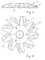
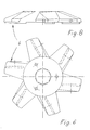
- a baffle ring 12 is installed in the direction of passage 3, seen from the first perforated disc 7, which is shown in FIGS. 2 and 3 is shown enlarged. It has a large number of approximately radial ram teeth 13. Viewed in the circumferential direction, the width of the tooth gaps 14 of adjacent teeth is approximately the same as the tooth width. However, because the width of the tooth gaps is selected to be constant in the exemplary embodiment, this determination relates there approximately to the tooth width on the outer circumference of the retaining ring 12.
- Fig. 3 reveals that the teeth 13 are essentially assigned to the inflow side 15 of the ring. Because of the special Shape of the ring cross-section, each tooth in the embodiment of FIG. 3 consists of a first tooth part 16, approximately triangular in side view, and a second tooth part 17 of approximately similar cross-sectional shape, the tips facing each other.
- the contour of the tooth base 18 is arch-shaped because the teeth are, as said, milled, in particular with the help of a side milling cutter.
- an inner contour was selected in the exemplary embodiment of FIG. 3, which consists of two angles to one another standing cone surfaces, the angle enclosed by both is designated there by 19.
- the cutting knife body 20 is star-shaped in all exemplary embodiments. Measured in the axial direction, it has at most approximately the same height as the retaining ring 12. In the exemplary embodiment, the height of the retaining ring is approximately one third greater than that of the cutting knife body 20. The latter, however, protrudes with its entire height as shown in FIG. 1 of the drawing the storage ring 20 into it. As a result, the aforementioned adaptation of the outer contour of the cutting knife body 20 to the inner contour of the retaining ring 12 is necessary insofar as both are directly associated with one another. It can be seen from FIG. 4, for example, that there an enveloping imaginary body of the cutting knife body 20 has approximately the same angle 23 as the angle 19 of the inner contour of the storage ring 12. A replaceable blade 25 is inserted into each arm 24 of the cutting knife body 20.
- a single arm of the cutting knife 6 or 8 is sufficient, but a rotation-symmetrical design is preferred for dynamic reasons alone. So far, two-arm cutting knives have been the preferred embodiment. If instead a larger number of arms is selected, for example as in the exemplary embodiments from 5 to 9, the effectiveness of the cutting set increases.
- a support ring 26 is located between the two cutting sets 4 and 5. This can also be designed in the manner of the retaining ring 12.
- FIG. 1 the correct proportions of cutting knife and perforated disc can be seen.
- the perforated disk of FIGS. 2 and 3 is shown on a somewhat smaller scale than the cutting knife of FIGS. 4 and 9.
- the retaining ring 12 With an outer diameter in the order of twelve cm, the retaining ring 12 preferably has eighteen teeth, with a tooth gap width 14 in the order of one cm.
Landscapes
- Engineering & Computer Science (AREA)
- Food Science & Technology (AREA)
- Crushing And Pulverization Processes (AREA)
Claims (5)
- Hachoir, notamment pour la viande ou matières équivalentes, comprenant deux jeux d'outils de coupe (4, 5) disposés l'un à la suite de l'autre dans le sens (3) du passage de la matière à hacher, composés chacun d'un disque perforé (7, 9) et d'un couteau rotatif (6, 8), cependant qu'il est prévu, au moins en amont du premier disque perforé (7), considéré dans le sens du passage, un anneau de retenue (12) qui est muni d'une pluralité de dents de retenue radiales (13), le couteau (20) étant engagé dans l'anneau de retenue (12), caractérisé en ce que l'anneau de retenue (12) présente une pluralité de dents de retenue radiales (13), de préférence de 8 à 20 dents de retenue, considérée dans la direction circonférentielle, la largeur des creux de denture (14) correspond à peu près à la largeur des dents mesurée à la périphérie extérieure de l'anneau de retenue (12), les creux de denture (14) présentent une largeur constante et le profil intérieur des dents de retenue (13) est à peu près incurvé en arc ou coudé en angle, l'angle inclus (19) étant concave.
- Hachoir selon la revendication 1, caractérisé en ce que les dents de retenue (13) sont essentiellement prévues sur la partie de l'anneau de retenue (12) qui est située sur le côté (15) d'arrivée du flux, notamment sur la moitié de l'anneau du côté de l'arrivée du flux, et ces dents, ou leur partie (16) côté arrivée du flux, présentent une forme sensiblement triangulaire dans une vue en élévation de côté.
- Hachoir selon la revendication 1 ou 2, caractérisé en ce que, mesuré dans la direction axiale, le corps (20) du couteau présente au maximum à peu près la même hauteur que l'anneau de retenue (12).
- Hachoir selon la revendication 3, caractérisé en ce que le corps (20) du couteau est engagé dans l'anneau de retenue (12) sensiblement sur toute sa hauteur, la surface enveloppe fictive du corps (20) du couteau, composé d'un moyeu (21) et de branches (22) qui partent sensiblement radialement, est espacée du profil intérieur de l'anneau de retenue (12) par une fente.
- Hachoir selon la revendication 4, caractérisé en ce que le couteau (6, 8) présente plus de deux branches (20), de préférence de cinq à douze branches, comprenant chacune au moins une lame interchangeable encastrée (25).
Applications Claiming Priority (2)
| Application Number | Priority Date | Filing Date | Title |
|---|---|---|---|
| DE8911353U DE8911353U1 (de) | 1989-09-23 | 1989-09-23 | Zerkleinerungsmaschine, insbesondere für Fleisch u.dgl. |
| DE8911353U | 1989-09-23 |
Publications (2)
| Publication Number | Publication Date |
|---|---|
| EP0420001A1 EP0420001A1 (fr) | 1991-04-03 |
| EP0420001B1 true EP0420001B1 (fr) | 1994-10-26 |
Family
ID=6843111
Family Applications (1)
| Application Number | Title | Priority Date | Filing Date |
|---|---|---|---|
| EP90117896A Expired - Lifetime EP0420001B1 (fr) | 1989-09-23 | 1990-09-18 | Hachoir pour viande |
Country Status (3)
| Country | Link |
|---|---|
| EP (1) | EP0420001B1 (fr) |
| DE (2) | DE8911353U1 (fr) |
| ES (1) | ES2066074T3 (fr) |
Families Citing this family (2)
| Publication number | Priority date | Publication date | Assignee | Title |
|---|---|---|---|---|
| US5699970A (en) * | 1996-07-11 | 1997-12-23 | 2 M Tool Co., Inc. | Meat-comminuting machine with improved vacuum discharge mechanism |
| EA000933B1 (ru) * | 1996-11-28 | 2000-06-26 | Эдуард Федорович Сыроватский | Способ измельчения мяса и мясорубка |
Family Cites Families (3)
| Publication number | Priority date | Publication date | Assignee | Title |
|---|---|---|---|---|
| US2665725A (en) * | 1953-04-10 | 1954-01-12 | Globe Slicing Machine Co Inc | Food chopper |
| DE1632132A1 (de) * | 1967-10-12 | 1970-10-29 | Strojirny Potravinarskeho Prum | Verfahren und Einrichtung zur insbesondere sehr feinen Fleischzerkleinerung |
| DE3620598C2 (de) * | 1986-06-19 | 1997-08-14 | Schnell Maschfab Karl | Vorrichtung zum automatischen Verstellen des Schneidsatzes einer Fleischzerkleinerungsmaschine |
-
1989
- 1989-09-23 DE DE8911353U patent/DE8911353U1/de not_active Expired
-
1990
- 1990-09-18 ES ES90117896T patent/ES2066074T3/es not_active Expired - Lifetime
- 1990-09-18 EP EP90117896A patent/EP0420001B1/fr not_active Expired - Lifetime
- 1990-09-18 DE DE59007555T patent/DE59007555D1/de not_active Expired - Fee Related
Also Published As
| Publication number | Publication date |
|---|---|
| DE8911353U1 (de) | 1989-11-02 |
| EP0420001A1 (fr) | 1991-04-03 |
| ES2066074T3 (es) | 1995-03-01 |
| DE59007555D1 (de) | 1994-12-01 |
Similar Documents
| Publication | Publication Date | Title |
|---|---|---|
| DE102019108306A1 (de) | Schneidmühle zum schneidenden Zerkleinern von Proben | |
| EP0538599A2 (fr) | Hacheuse | |
| EP0124138B1 (fr) | Méthode et dispositif pour le broyage de produits végétaux | |
| EP0387868B1 (fr) | Dispositif de broyage pour déchets de bois | |
| EP2017008B1 (fr) | Ensemble de coupe doté d'au moins une plaque perforée ou de séparation comprenant des canaux de passage | |
| WO1998028079A1 (fr) | Hache-viande | |
| DE2809609C2 (de) | Schneidsatz für Fleischwölfe | |
| EP0420001B1 (fr) | Hachoir pour viande | |
| DE3306068A1 (de) | Zerkleinerungsvorrichtung und verfahren insbesondere zur herstellung von holzspaenen | |
| DE2154353C2 (de) | Schneidmaschine für Fleischwaren o.dgl. | |
| DE3313517A1 (de) | Granulator | |
| DE3230542A1 (de) | Zerkleinerungsvorrichtung | |
| DE1279415B (de) | Einteilige Messertrommel fuer Haeckselmaschinen | |
| DE650591C (de) | Maschine zum Schneiden von Fleisch u. dgl. | |
| DE3432725C2 (fr) | ||
| DE10113953C1 (de) | Vorrichtung zum Zerkleinern von Kunststoffgebilden mit geringer Materialstärke | |
| DE2451313A1 (de) | Vorrichtung zum vorzerkleinern von gefriergut | |
| DE2618254A1 (de) | Messertrommel, insbesondere fuer hackmaschinen zur zerkleinerung von hoelzern und abfaellen | |
| EP0420000B1 (fr) | Outil de coupe pour machine à broyer | |
| DE3522615A1 (de) | Haeckselmaschine | |
| DE4410566A1 (de) | Feinstzerkleinerungsanlage zur Herstellung von Brät | |
| CH553004A (de) | Zerkleinerungsmaschine, besonders fuer abfaelle. | |
| AT384752B (de) | Zerkleinerungsvorrichtung, insbesondere fuer futtermittel od.dgl. | |
| DE650549C (de) | Vorrichtung zur Zerkleinerung von Fleisch, Fischen, Knochen, Graeten, ganzen Tierkoerpern und aehnlichen Stoffen | |
| DE816924C (de) | Maschine zum Zerkleinern von Viehfutter |
Legal Events
| Date | Code | Title | Description |
|---|---|---|---|
| PUAI | Public reference made under article 153(3) epc to a published international application that has entered the european phase |
Free format text: ORIGINAL CODE: 0009012 |
|
| AK | Designated contracting states |
Kind code of ref document: A1 Designated state(s): DE ES FR GB IT |
|
| 17P | Request for examination filed |
Effective date: 19910227 |
|
| 17Q | First examination report despatched |
Effective date: 19920511 |
|
| GRAA | (expected) grant |
Free format text: ORIGINAL CODE: 0009210 |
|
| AK | Designated contracting states |
Kind code of ref document: B1 Designated state(s): DE ES FR GB IT |
|
| GBT | Gb: translation of ep patent filed (gb section 77(6)(a)/1977) |
Effective date: 19941101 |
|
| REF | Corresponds to: |
Ref document number: 59007555 Country of ref document: DE Date of ref document: 19941201 |
|
| ITF | It: translation for a ep patent filed | ||
| ET | Fr: translation filed | ||
| REG | Reference to a national code |
Ref country code: ES Ref legal event code: FG2A Ref document number: 2066074 Country of ref document: ES Kind code of ref document: T3 |
|
| PLBE | No opposition filed within time limit |
Free format text: ORIGINAL CODE: 0009261 |
|
| STAA | Information on the status of an ep patent application or granted ep patent |
Free format text: STATUS: NO OPPOSITION FILED WITHIN TIME LIMIT |
|
| 26N | No opposition filed | ||
| PGFP | Annual fee paid to national office [announced via postgrant information from national office to epo] |
Ref country code: ES Payment date: 20010917 Year of fee payment: 12 |
|
| REG | Reference to a national code |
Ref country code: GB Ref legal event code: IF02 |
|
| PGFP | Annual fee paid to national office [announced via postgrant information from national office to epo] |
Ref country code: FR Payment date: 20020829 Year of fee payment: 13 |
|
| PG25 | Lapsed in a contracting state [announced via postgrant information from national office to epo] |
Ref country code: ES Free format text: LAPSE BECAUSE OF NON-PAYMENT OF DUE FEES Effective date: 20020919 |
|
| PGFP | Annual fee paid to national office [announced via postgrant information from national office to epo] |
Ref country code: GB Payment date: 20020923 Year of fee payment: 13 |
|
| PGFP | Annual fee paid to national office [announced via postgrant information from national office to epo] |
Ref country code: DE Payment date: 20021023 Year of fee payment: 13 |
|
| PG25 | Lapsed in a contracting state [announced via postgrant information from national office to epo] |
Ref country code: GB Free format text: LAPSE BECAUSE OF NON-PAYMENT OF DUE FEES Effective date: 20030918 |
|
| PG25 | Lapsed in a contracting state [announced via postgrant information from national office to epo] |
Ref country code: DE Free format text: LAPSE BECAUSE OF NON-PAYMENT OF DUE FEES Effective date: 20040401 |
|
| REG | Reference to a national code |
Ref country code: ES Ref legal event code: FD2A Effective date: 20031011 |
|
| GBPC | Gb: european patent ceased through non-payment of renewal fee |
Effective date: 20030918 |
|
| PG25 | Lapsed in a contracting state [announced via postgrant information from national office to epo] |
Ref country code: FR Free format text: LAPSE BECAUSE OF NON-PAYMENT OF DUE FEES Effective date: 20040528 |
|
| REG | Reference to a national code |
Ref country code: FR Ref legal event code: ST |
|
| PG25 | Lapsed in a contracting state [announced via postgrant information from national office to epo] |
Ref country code: IT Free format text: LAPSE BECAUSE OF NON-PAYMENT OF DUE FEES;WARNING: LAPSES OF ITALIAN PATENTS WITH EFFECTIVE DATE BEFORE 2007 MAY HAVE OCCURRED AT ANY TIME BEFORE 2007. THE CORRECT EFFECTIVE DATE MAY BE DIFFERENT FROM THE ONE RECORDED. Effective date: 20050918 |