EP0538599A2 - Hacheuse - Google Patents
Hacheuse Download PDFInfo
- Publication number
- EP0538599A2 EP0538599A2 EP92115088A EP92115088A EP0538599A2 EP 0538599 A2 EP0538599 A2 EP 0538599A2 EP 92115088 A EP92115088 A EP 92115088A EP 92115088 A EP92115088 A EP 92115088A EP 0538599 A2 EP0538599 A2 EP 0538599A2
- Authority
- EP
- European Patent Office
- Prior art keywords
- stage
- chopper according
- knife
- knives
- elevations
- Prior art date
- Legal status (The legal status is an assumption and is not a legal conclusion. Google has not performed a legal analysis and makes no representation as to the accuracy of the status listed.)
- Granted
Links
Images






Classifications
-
- A—HUMAN NECESSITIES
- A01—AGRICULTURE; FORESTRY; ANIMAL HUSBANDRY; HUNTING; TRAPPING; FISHING
- A01F—PROCESSING OF HARVESTED PRODUCE; HAY OR STRAW PRESSES; DEVICES FOR STORING AGRICULTURAL OR HORTICULTURAL PRODUCE
- A01F12/00—Parts or details of threshing apparatus
- A01F12/40—Arrangements of straw crushers or cutters
-
- A—HUMAN NECESSITIES
- A01—AGRICULTURE; FORESTRY; ANIMAL HUSBANDRY; HUNTING; TRAPPING; FISHING
- A01F—PROCESSING OF HARVESTED PRODUCE; HAY OR STRAW PRESSES; DEVICES FOR STORING AGRICULTURAL OR HORTICULTURAL PRODUCE
- A01F29/00—Cutting apparatus specially adapted for cutting hay, straw or the like
- A01F29/02—Cutting apparatus specially adapted for cutting hay, straw or the like having rotating knives with their cutting edges in a plane perpendicular to their rotational axis
Definitions
- the invention relates to a chopper, in particular Anbauhburgs ler for combine harvesters, with a drum, consisting of a rotating about a substantially horizontal axis shaft, on the circumference of which knives are preferably pivotally arranged, which have a cutting edge on their longitudinal side, with in the knife Circulating circle protruding, preferably fixed counter-knives and with a guide plate adjoining the counter-knives in the direction of rotation of the drum, arranged essentially concentrically to and at a distance from the knife-rotating circuit, on which an inward-pointing retaining element is provided at a distance from the counter-knives.
- Such a chopper is known from EP 415 419 A2.
- the knives which can also be called flail knives, are pivotally mounted on the circumference of the rotating knife shaft.
- the fixed counter knives are located between the rotating knives.
- a cross bar serves as a retaining element.
- an essentially funnel-shaped feed opening is provided, which is used in particular to feed straw.
- a splice chopper which has a substantially horizontal, driven rotor shaft mounted in a trough-shaped housing, to which a plurality of radially projecting tools serving for comminution are fastened with end edges inclined at an angle to the shaft axis in such a way that these one ends Form milling and / or cutting envelope cylinders.
- An upper inlet funnel is connected to the housing.
- the Crushing tools are designed as axially conveying devices which transport the material starting from the central region of the enveloping cylinder to the lateral ejection openings.
- counter knives are not available in the chopper known from EP 331 784 A1. In the drum direction of rotation behind the inlet funnel, several strips are arranged that form a friction floor.
- a straw shredding and grating device which consists of a rotating drum with strips or pins and associated basket.
- the rotating drum is preceded by a pair of squeeze rollers, which feeds the straw coming from the shaker or separately supplied straw to the shredding and grating device and holds it in place during the shredding process.
- the revolving drum therefore has no knives, only strips or pens. There is also no funnel-shaped feed opening. Rather, the material to be shredded is supplied by the pair of squeeze rollers mentioned. Counter knives are also not provided.
- the object of the invention is to improve the chopping effect of the device described above and known from EP 415 419.
- the retaining element consists of a first stage and a second stage following in the direction of drum rotation, the second stage consisting of several elevations.
- the first stage can also be called a preliminary stage. It consists of a radial section, ie a part that runs essentially in the direction of the drum axis of rotation.
- the second stage is behind it in the direction of drum rotation.
- the guide plate has step-shaped retaining elements, the second step having several elevations having.
- the second stage can be designed, for example, as a friction plate known per se.
- the advantage of the invention is that the straw that has already been cut and that has passed through the counter knife is retained at the preliminary stage. Straws that have passed the counter knife in the direction of rotation and are still uncut are transversely directed through the first stage. This effect is particularly pronounced when the first stage is relatively large. At this first stage, there is a further cutting, in particular of the stalks which are transverse to it. Then the crop reaches the second stage, which is designed, for example, as a friction floor and, in a manner known per se, consists of a plurality of transverse strips arranged one behind the other. The depth of the cross strips of the second level can be less than the depth of the first level. In this second stage, the stalks are further shredded and split lengthways. Overall, stalks conveyed in the direction of rotation of the drum are placed even better and more reliably across.
- the first level can be higher than the second level or its surveys.
- the first stage extends further outward in the radial direction, as seen from the drum axis of rotation, than the second stage.
- the first level (preliminary stage) can also be lower than the second level or its surveys. According to a further advantageous development, the first stage (preliminary stage) is just as high as the second stage or its surveys.
- the first stage can be designed as a trough.
- the guide plate preferably runs in the area in front of the first Ascending level. The increase takes place in the direction of drum rotation. In the direction of drum rotation, the radial distance from the axis of rotation of the drum becomes smaller.
- the height of the first stage is preferably adjustable, as a result of which the device can be adapted to different operating conditions and requirements.
- the guide plate is designed to be pivotable in the area in front of the first stage. This can ensure that the guide plate rises in the manner already described before the first stage.
- the degree of inclination can also be adjusted and thus adapted to different requirements.
- the axis about which the guide plate can be pivoted is preferably relatively close to the guide plate.
- the pivotable part of the guide plate, starting from this pivot axis, runs in the direction of drum rotation.
- the first stage can have a cutting edge. This cutting edge preferably projects into the knife circulation circuit. It is then interrupted in the area of the knives.
- the guide plate can have an expanding area behind the second stage in the direction of rotation of the drum. This area can be designed in the manner of an expanding funnel. The shredded but slowed down stalk material is accelerated again in the widening area. From there it can be directed into a suitable distribution device.
- a further advantageous development is characterized by a third stage at the rear end of the second stage in the direction of drum rotation. This has proven to be expedient and advantageous for the acceleration and flow processes just mentioned.
- the second stage is preferably designed as a friction plate consisting of several elevations.
- the height of the second stage or of the friction plate is preferably adjustable.
- the ridges of the friction plate can protrude into the knife circulation circuit in the area between the knives. In the area of the knives there are openings in the ridges.
- the friction floor preferably consists of several transverse bars arranged one behind the other.
- the increases in the friction floor can also be wave-shaped.
- the friction base and its elevations are preferably made in one piece, for example from a sheet metal.
- the increases in the friction floor can also consist of individual pins. These pegs can be round, rectangular, square or of any other shape.
- elevations of the friction floor can consist of interrupted cross bars. These cross bars can be arranged offset.
- the elevations of the friction floor can also consist of strips arranged in a zigzag pattern or of strips arranged alternately diagonally.
- the retaining element consists of a unit which forms a first stage and a second stage which follows in the direction of drum rotation, the second stage comprising several Surveys exist.
- the preliminary stage and the second stage which can be designed as a friction floor, are combined into one unit.
- the unit consisting of the first and the second stage is preferably detachably connected to the guide plate. This unit can then be installed or removed as required for different crops.
- the height of the unit is preferably adjustable. This creates an opportunity to adapt to different circumstances and requirements.
- a further advantageous development is characterized in that the unit consisting of the first and second stage is rotatable.
- the unit can then preferably be rotated through 180 ° and locked in either of its two positions. This also creates an opportunity to adapt to different crops.
- a smooth bottom is preferably provided on one side of the unit.
- the knives are designed in a cutting shape on their end face. This is known per se from European patent application 90 116 672.8, to which express reference is hereby made.
- the chopping effect is further improved by the fact that the knives have a cutting edge not only on their long side but also on their front side.
- the cutting edge on the end face can be smooth or corrugated or of another form known per se from the European patent application 90 116 672.8 mentioned.
- the rear area of the combine 1 shown in FIG. 1 consists of a housing 2 with a rear end plate 3.
- the shaker 4 is arranged in the housing 2, from which the straw 5 is fed to the chopper 6.
- the sieves 7 are arranged under the shaker 4.
- the straw 5 is fed to the chopper 6 through a feed opening 8 which lies at the end of a feed plate 9.
- the feed plate 9 is arranged inclined such that a feed funnel leading to the feed opening 8 is formed.
- the fixed counter knives 10 which protrude into the circuit 11 of the flail knives 12 and which are located between the flail knives 12.
- the counter knives 10 are firmly connected to the feed plate 9 via a mounting rail 13.
- the straw 5 is distributed by a distribution device 14 of a type known per se.
- FIG. 2 shows the chopper 6 in an enlarged representation. It has a drum which consists of a knife shaft 16 rotating about an essentially horizontal axis 15, on the circumference of which four knives 12 are each pivotable about axes 17.
- the counter knife 10 is followed in the drum rotation direction 20 by a guide plate 21 which is essentially concentric to the knife circulating circuit 11 and at a distance from the knife circulating circuit 11.
- the guide plate 21 has inward-pointing retaining elements which, viewed in the direction of rotation 20 of the knife circulation circuit 11, are at a distance behind the counter knives 10 and which are described in detail below.
- the retaining elements of the guide plate 21 consist of a first stage 22 and a second stage 23 following in the direction of drum rotation 20.
- the first stage (preliminary stage) 22 is larger than the second stage 23 behind it - in the drum direction of rotation 20 Chopping effect improved. Those stalks that are conveyed in the direction of rotation, that is, parallel to the knife circulation circuit 11, are even better laid crosswise. A further cutting takes place at the preliminary stage 22 before the crop reaches the subsequent second stage, where it is further chopped up.
- the first stage 22 is designed as a bevel 24 pointing towards the drum axis of rotation 15.
- the guide plate 21 is designed as a trough 25.
- the second stage 23 is composed of a plurality of elevations 26 Friction floor 27 designed.
- the elevation 28 of the friction base 27 which is furthest forward in the direction of rotation 20 of the knife adjoins the bevel 24 of the first stage 22 flush. This increases the first stage 22 further.
- the radially inner ends of the elevations 26 lie outside the knife circulation circuit 11.
- the elevations 26 are designed as a plurality of transverse strips arranged one behind the other. They form successive stages, the depth and spacing of which are kept smaller than in the first stage 22. This measure enables the straws to be further reduced in the longitudinal direction in the region of the second stage 23.
- a third step 29 which is designed as a sheet 30 that widens in the radial direction. In this way, the stalk material which has been comminuted by the friction base 27 but also braked is accelerated again. It is directed into the distribution device 14 (omitted in FIG. 2 for reasons of the simplified drawing).
- the guide plate 21 is formed in one piece. It consists of the trough 25, the fold 24 forming the first step 22, the second step 23 and the third step 29. In the area of the second step 23, the transverse strips 26, which form the friction floor 27, are connected to the guide plate 21.
- the guide plate is designed to be pivotable in the trough-shaped region 25 in front of the first step 22.
- a pivot plate 32 is pivotally mounted about an axis 33 provided on the guide plate and parallel to the axis of rotation 15 of the drum. The pivoting possibility is indicated by the double arrow 34.
- the swivel plate 32 can be locked in different swivel positions. As a result, the height of the first step 22 formed by the bevel 24 is adjustable. In the area of the swivel plate 32, the guide plate accordingly rises, to a different extent depending on the swivel position.
- the retaining elements of the guide plate consist of a unit 35 which forms the first stage 22 and the second stage 23 which follows in the direction of drum rotation 20, the first stage 22 again being higher than the second stage 23, which is considered to be from several spaced cross bars 26 existing friction floor 27 is configured.
- the unit 35 is formed by a U-shaped plate which can be detachably connected to the guide plate 21 by means of screws or similar fastening elements 36 (only indicated in the drawing).
- the first stage is formed by the leg 37 of the U-shaped unit 35 lying at the front in the drum rotation direction 20.
- the rear leg 31 of the U-shaped unit 35 forms the further step 31 already explained above (see FIG. 3).
- the first stage 22, the second stage 23 and the further stage 31 are in turn formed by a unit 35 which, however, this time is variable in the direction 38 towards the drum axis of rotation 15, so that the height of the unit 35 and thus the height of the steps is adjustable.
- the changeover of the unit 35 required in the embodiment of FIG. 5 can be simplified or avoided.
- An individual setting of the step heights depending on the requirements of the respective application is made possible.
- the unit 35 - as required for different crops - installed or removed.
- the step heights are set individually in a manner which is improved in comparison with this. In extreme cases, the step heights can be adjusted to such an extent that the unit again forms a smooth bottom, as is shown in FIG. 11.
- the strips 26 of the friction base 27 are connected at their radially outer ends to a guide strip 39.
- the strips 26 are also guided in openings of the unit 35. As a result, the height of the strips 26 can be adjusted relative to the unit 35, which creates a further possibility of adaptation to different crops.
- the friction base 27 is formed by a corrugated plate 40 which is integral with the guide plate 21.
- the corrugated sheet 40 can have round or triangular or other waves. This can influence the cutting conditions and the power requirement.
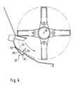
- the bevel 24 forming the first step 22 has a cutting edge 41, the upper area 42 of which protrudes into the knife circulating circuit 11.
- the cutting edge 41 points in the radial direction to the drum axis of rotation 15.
- the cutting edge 41 and the strips 26 of the friction base 27 are shown from above (in the direction of the arrow 43).
- the strips 26 also protrude into the knife circulation circuit 11.
- openings 44 are present in the area of the circulation circles of these knives, both in the strips 26 and in the cutting edge 41.
- the cutting edges 41 and the strips 26 are interrupted by these openings 44 .
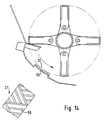
- the elevations of the friction base 27 consist of individual pins 45 which are round or rectangular or square in cross section or of some other shape can.
- FIGS. 10 and 11 an embodiment is shown in which - like in FIGS. 5 and 6 - the steps consist of a unit 35, but this time is rotatably mounted about an axis 46 running parallel to the drum axis of rotation 15 , as indicated by the double arrow 47.
- the unit 35 is formed by a box profile 48. On one side 49, the transverse strips 26 forming the friction base 27 are fastened. A smooth bottom 50 is provided on the opposite side of the box section.
- the unit 35 can be locked in the two positions shown in FIGS. 10 and 11, pivoted through 180 °. In the embodiment of FIGS. 10 and 11, the preliminary stage and the friction plate and also the further stage are combined to form a rotatable unit 35. By rotating the unit 35 by 180 ° about the axis 46, a quick changeover for different harvesting conditions is created.
- the elevations of the friction base 27 consist of interrupted transverse strips 51. Between the elevations 51 there are gaps 52 which are arranged offset from one another from one row 53 to the next row 53.
- the friction base 27 consists of strips 55 arranged in a zigzag fashion in the flow direction 54 of the chopped material.
- the friction floor 27 consists of alternately diagonally arranged strips 56.
- FIGS. 9, 12, 13 and 14 particularly reliably prevents the friction floor 27 from becoming clogged by the chopped material, but being kept clear by sweeping over the chopped material and thus maintaining its effect.
- FIG. 15 shows an embodiment which corresponds essentially to that of FIG. 2, in which, however, the bar 26 (in the FIG. 2 designated as bar 28) of the friction plate 27 lying at the front in the drum rotation direction 20 has been omitted.
- the strips of the second stage do not begin at the same point as the first stage, as in FIG. 2, but somewhat behind it in the direction of drum rotation.
- the first step 22, the second step 21 and the third step 29 are formed in one piece from a single sheet by means of folds.
- the height of the first step 22 is the same as the height of the elevations 60 forming the second step 21.
- the guide plate contains several folds which serve as retaining elements.
Landscapes
- Life Sciences & Earth Sciences (AREA)
- Environmental Sciences (AREA)
- Threshing Machine Elements (AREA)
- Harvester Elements (AREA)
- Amplifiers (AREA)
- Organic Low-Molecular-Weight Compounds And Preparation Thereof (AREA)
Applications Claiming Priority (2)
| Application Number | Priority Date | Filing Date | Title |
|---|---|---|---|
| DE4135165 | 1991-10-24 | ||
| DE4135165A DE4135165C2 (de) | 1991-10-24 | 1991-10-24 | Häcksler |
Publications (3)
| Publication Number | Publication Date |
|---|---|
| EP0538599A2 true EP0538599A2 (fr) | 1993-04-28 |
| EP0538599A3 EP0538599A3 (en) | 1994-06-22 |
| EP0538599B1 EP0538599B1 (fr) | 2000-12-13 |
Family
ID=6443360
Family Applications (1)
| Application Number | Title | Priority Date | Filing Date |
|---|---|---|---|
| EP92115088A Expired - Lifetime EP0538599B1 (fr) | 1991-10-24 | 1992-09-03 | Hacheuse |
Country Status (9)
| Country | Link |
|---|---|
| EP (1) | EP0538599B1 (fr) |
| CN (1) | CN1072055A (fr) |
| AT (1) | ATE198020T1 (fr) |
| CA (1) | CA2081240A1 (fr) |
| CZ (1) | CZ321292A3 (fr) |
| DE (2) | DE4135165C2 (fr) |
| HU (1) | HUT66029A (fr) |
| PL (1) | PL296302A1 (fr) |
| SK (1) | SK321292A3 (fr) |
Cited By (14)
| Publication number | Priority date | Publication date | Assignee | Title |
|---|---|---|---|---|
| EP0702892A1 (fr) * | 1994-09-07 | 1996-03-27 | CLAAS KGaA | Accessoire hacheur à large épandage pour matière à hacher en particulier le mélange de balles et de menues pailles d'une moissoneuse-batteuse |
| WO1997011594A1 (fr) * | 1995-09-25 | 1997-04-03 | Biso B.V. | Hache-paille pour broyer la paille derriere les dispositifs de separation des grains d'une moissonneuse batteuse |
| WO1998010634A1 (fr) * | 1996-09-10 | 1998-03-19 | Biso B.V. | Systeme a hacher la paille pour broyer de la paille derriere les dispositifs de separation du grain d'une moissonneuse-batteuse combinee |
| EP0916251A1 (fr) * | 1997-11-07 | 1999-05-19 | Franz Schrattenecker | Hacheuse pour produits de récolte |
| EP0960561A1 (fr) * | 1998-05-26 | 1999-12-01 | Franz Schrattenecker | Hacheuse pour produits de récolte |
| EP1247443A1 (fr) * | 2001-04-05 | 2002-10-09 | CLAAS Selbstfahrende Erntemaschinen GmbH | Dispositif de hachage |
| US6634581B2 (en) | 2000-01-12 | 2003-10-21 | Georg Rutz | Field shredder with a friction base |
| WO2007125557A1 (fr) * | 2006-05-03 | 2007-11-08 | Tierre S.R.L. | Nouvelle unite de couteau/broyage pour machines de broyage agricoles et industrielles |
| GB2477076A (en) * | 2008-07-16 | 2011-07-27 | Richard Larrington | Apparatus and method for producing straw of a predetermined length |
| US8092286B2 (en) | 2007-05-23 | 2012-01-10 | Cnh America Llc | Concave pan portion of an integral chopper assembly of a combine harvester |
| EP2837280A1 (fr) * | 2013-08-01 | 2015-02-18 | CLAAS Selbstfahrende Erntemaschinen GmbH | Moissonneuse-batteuse équipée d'un dispositif de hache-paille |
| BE1021638B1 (de) * | 2012-03-26 | 2015-12-21 | Claas Saulgau Gmbh | Feldhäcksler mit reibboden. |
| EP2965615A1 (fr) | 2014-07-08 | 2016-01-13 | CNH Industrial Belgium nv | Système de manipulation de résidu pour moissonneuse-batteuse |
| US10130039B2 (en) | 2015-08-28 | 2018-11-20 | Cnh Industrial America Llc | Agricultural harvester including feedback control of chopping parameters |
Families Citing this family (10)
| Publication number | Priority date | Publication date | Assignee | Title |
|---|---|---|---|---|
| US8590355B2 (en) | 2004-04-19 | 2013-11-26 | Rasspe Systemtechnik Gmbh & Co. Kg | Chopping blade and counterblade for a chopping device and process for its production |
| CN102007842A (zh) * | 2009-09-08 | 2011-04-13 | 刘勇 | 滚刀式铡草机 |
| CN105917874A (zh) * | 2016-05-19 | 2016-09-07 | 河南盛和明威实业有限公司 | 玉米秸秆粉碎机 |
| DE102018133505B3 (de) * | 2018-12-21 | 2020-03-26 | Konrad Hendlmeier | Schneidvorrichtung zum Zerkleinern von Ernterückständen oder Pflanzenteilen |
| CN109964662A (zh) * | 2019-02-26 | 2019-07-05 | 中国农业大学烟台研究院 | 一种沼气工程用智能化原料收运设备 |
| US11724263B2 (en) * | 2019-10-25 | 2023-08-15 | Sesh Technologies Manufacturing Inc. | Dual-blade agricultural grinder |
| CN112868404B (zh) * | 2021-01-18 | 2023-09-26 | 洞玛生物技术(深圳)有限公司 | 一种草本植物自动萃取装置 |
| EP4088558B1 (fr) * | 2021-05-12 | 2024-02-28 | CNH Industrial Belgium N.V. | Agencement de broyeur pour moissonneuse agricole |
| PL244688B1 (pl) * | 2021-08-30 | 2024-02-26 | Univ Technologiczno Przyrodniczy Im Jana I Jedrzeja Sniadeckich W Bydgoszczy | Bębnowy zespół tnący sieczkarni |
| CN114982488B (zh) * | 2022-06-08 | 2023-04-25 | 中国农业大学 | 一种自适应变直径滚筒及切碎滚刀 |
Family Cites Families (8)
| Publication number | Priority date | Publication date | Assignee | Title |
|---|---|---|---|---|
| DE823063C (de) * | 1950-05-25 | 1953-06-05 | Josef Dechentreiter | Strohzerkleinerungs- und Reibevorrichtung |
| GB1043712A (en) * | 1963-02-05 | 1966-09-21 | Massey Furguson G M B H | Straw chopper |
| DE3316241A1 (de) * | 1983-05-04 | 1984-11-08 | Claas Saulgau GmbH, 7968 Saulgau | Maishaecksler mit einem reibboden |
| DE3574231D1 (en) * | 1984-01-31 | 1989-12-21 | Wieneke Franz | Device for grinding, granular and/or fibrous material |
| DE3444502A1 (de) * | 1984-12-06 | 1986-06-12 | Franz Prof. Dr.-Ing. 3406 Bovenden Wieneke | Einrichtung zum zerkleinern und aufbereiten von halmgut insbesondere von silomais |
| ES2026587T3 (es) * | 1988-03-10 | 1992-05-01 | Franz Prof. Dr.-Ing. Wieneke | Cortapajas deshilachador. |
| DD287189B5 (de) * | 1989-08-21 | 1993-06-03 | Landtechnik Ag Schoenebeck | Zerkleinerungseinrichtung fuer feldhaecksler |
| DE59008064D1 (de) * | 1989-09-01 | 1995-02-09 | Biso Maschf Gmbh | Häcksler. |
-
1991
- 1991-10-24 DE DE4135165A patent/DE4135165C2/de not_active Expired - Fee Related
-
1992
- 1992-09-03 AT AT92115088T patent/ATE198020T1/de not_active IP Right Cessation
- 1992-09-03 EP EP92115088A patent/EP0538599B1/fr not_active Expired - Lifetime
- 1992-09-03 DE DE59209881T patent/DE59209881D1/de not_active Expired - Lifetime
- 1992-10-15 CN CN92111498A patent/CN1072055A/zh active Pending
- 1992-10-20 HU HU9203292A patent/HUT66029A/hu unknown
- 1992-10-21 PL PL29630292A patent/PL296302A1/xx unknown
- 1992-10-23 SK SK3212-92A patent/SK321292A3/sk unknown
- 1992-10-23 CA CA002081240A patent/CA2081240A1/fr not_active Abandoned
- 1992-10-24 CZ CS923212A patent/CZ321292A3/cs unknown
Cited By (22)
| Publication number | Priority date | Publication date | Assignee | Title |
|---|---|---|---|---|
| EP0702892A1 (fr) * | 1994-09-07 | 1996-03-27 | CLAAS KGaA | Accessoire hacheur à large épandage pour matière à hacher en particulier le mélange de balles et de menues pailles d'une moissoneuse-batteuse |
| WO1997011594A1 (fr) * | 1995-09-25 | 1997-04-03 | Biso B.V. | Hache-paille pour broyer la paille derriere les dispositifs de separation des grains d'une moissonneuse batteuse |
| US5928080A (en) * | 1995-09-25 | 1999-07-27 | Biso B.V | Device for chopping the stalks after the ears of corn have been cut off in a combine harvester |
| EP1438887A3 (fr) * | 1995-09-25 | 2004-09-15 | Biso B.V. | Hache-paille pour broyer la paille derrière les dispositifs de séparation des grains d'une moissonneuse batteuse |
| WO1998010634A1 (fr) * | 1996-09-10 | 1998-03-19 | Biso B.V. | Systeme a hacher la paille pour broyer de la paille derriere les dispositifs de separation du grain d'une moissonneuse-batteuse combinee |
| US6196483B1 (en) | 1996-09-10 | 2001-03-06 | Biso B.V. | Chaft cutter for comminuting haulm behind the grain-separator devices of a combine harvester |
| EP0916251A1 (fr) * | 1997-11-07 | 1999-05-19 | Franz Schrattenecker | Hacheuse pour produits de récolte |
| EP0960561A1 (fr) * | 1998-05-26 | 1999-12-01 | Franz Schrattenecker | Hacheuse pour produits de récolte |
| US6634581B2 (en) | 2000-01-12 | 2003-10-21 | Georg Rutz | Field shredder with a friction base |
| EP1247443A1 (fr) * | 2001-04-05 | 2002-10-09 | CLAAS Selbstfahrende Erntemaschinen GmbH | Dispositif de hachage |
| WO2007125557A1 (fr) * | 2006-05-03 | 2007-11-08 | Tierre S.R.L. | Nouvelle unite de couteau/broyage pour machines de broyage agricoles et industrielles |
| US8092286B2 (en) | 2007-05-23 | 2012-01-10 | Cnh America Llc | Concave pan portion of an integral chopper assembly of a combine harvester |
| GB2477076A (en) * | 2008-07-16 | 2011-07-27 | Richard Larrington | Apparatus and method for producing straw of a predetermined length |
| GB2477076B (en) * | 2008-07-16 | 2013-01-02 | Richard Larrington | Handling fibrous material |
| BE1021638B1 (de) * | 2012-03-26 | 2015-12-21 | Claas Saulgau Gmbh | Feldhäcksler mit reibboden. |
| EP2837280A1 (fr) * | 2013-08-01 | 2015-02-18 | CLAAS Selbstfahrende Erntemaschinen GmbH | Moissonneuse-batteuse équipée d'un dispositif de hache-paille |
| EP2837280B1 (fr) | 2013-08-01 | 2017-04-12 | CLAAS Selbstfahrende Erntemaschinen GmbH | Moissonneuse-batteuse équipée d'un dispositif de hache-paille |
| RU2658384C2 (ru) * | 2013-08-01 | 2018-06-21 | КЛААС Зельбстфаренде Эрнтемашинен ГмбХ | Зерновой комбайн с измельчительным устройством |
| EP2965615A1 (fr) | 2014-07-08 | 2016-01-13 | CNH Industrial Belgium nv | Système de manipulation de résidu pour moissonneuse-batteuse |
| US9635813B2 (en) | 2014-07-08 | 2017-05-02 | Cnh Industrial America Llc | Residue handling system for an agricultural harvester |
| US10588261B2 (en) | 2014-07-08 | 2020-03-17 | Cnh Industrial America Llc | Residue handling system for an agricultural harvester |
| US10130039B2 (en) | 2015-08-28 | 2018-11-20 | Cnh Industrial America Llc | Agricultural harvester including feedback control of chopping parameters |
Also Published As
| Publication number | Publication date |
|---|---|
| EP0538599B1 (fr) | 2000-12-13 |
| EP0538599A3 (en) | 1994-06-22 |
| CN1072055A (zh) | 1993-05-19 |
| ATE198020T1 (de) | 2000-12-15 |
| CA2081240A1 (fr) | 1993-04-25 |
| DE4135165C2 (de) | 1998-04-09 |
| HUT66029A (en) | 1994-09-28 |
| SK321292A3 (en) | 1995-10-11 |
| CZ321292A3 (en) | 1993-05-12 |
| DE59209881D1 (de) | 2001-01-18 |
| DE4135165A1 (de) | 1993-04-29 |
| PL296302A1 (en) | 1993-10-04 |
Similar Documents
| Publication | Publication Date | Title |
|---|---|---|
| DE4135165C2 (de) | Häcksler | |
| DE2729033C2 (fr) | ||
| DE3302980C2 (fr) | ||
| EP0415419B1 (fr) | Hachoir | |
| DE4036717A1 (de) | Pflueckvorsatz fuer ein erntegeraet | |
| EP1232683A1 (fr) | Eléments entraíneurs ef dispositif broyeur pour machine agricole | |
| DE4111981A1 (de) | Maschine zum maehen und haeckseln von mais und dgl. stengelartigem erntegut | |
| EP0286882A2 (fr) | Faucheuse | |
| EP0748583B1 (fr) | Moissonneuse-batteuse | |
| EP1671532B1 (fr) | Rotor hacheur | |
| DE2118914A1 (de) | Aus wenigstens einem Paar zusammenwirkender Mähkreisel bestehendes Mähwerk und nachgeschaltetem Quetschwalzenpaar bestehende Halmgutaufbereitungsmaschine | |
| EP0423626B1 (fr) | Dispositif à ramasser pour récolter des céréales, en particulier de mais | |
| DE3234657C2 (fr) | ||
| EP0787426B1 (fr) | Dispositif convoyeur pour moissonneuse | |
| EP0153621A1 (fr) | Hacheuse à tambour avec une broyeuse secondaire | |
| DE3306068A1 (de) | Zerkleinerungsvorrichtung und verfahren insbesondere zur herstellung von holzspaenen | |
| DE3727535C2 (de) | Pflückvorrichtung zum Ernten von Halmfrüchten, insbesondere Mais | |
| EP0568961A2 (fr) | Hâcheuse de balles | |
| DE1279415B (de) | Einteilige Messertrommel fuer Haeckselmaschinen | |
| DE2502474C2 (de) | Zerkleinerungsvorrichtung für Erntegut | |
| DE102009028410B4 (de) | Strohhäcksler eines Mähdreschers | |
| DE19600390A1 (de) | Mähdrescher | |
| DE102019007585A1 (de) | Reihenunabhängiges Vorsatzgerät zum Ernten stängelförmiger Pflanzen mit einem quer zur Fahrtrichtung liegenden, durch das ganze Vorsatzgerät durchgehenden Pflückspalt | |
| DE69003747T2 (de) | Entnahmefräse und Transportgerät. | |
| DE3324898A1 (de) | Schneid- und zufuehreinrichtung fuer eine gezogene oder fuer den dreipunktanbau am schlepper vorgesehene maschine zum ernten von mais o.dgl. stengelartigem erntegut |
Legal Events
| Date | Code | Title | Description |
|---|---|---|---|
| PUAI | Public reference made under article 153(3) epc to a published international application that has entered the european phase |
Free format text: ORIGINAL CODE: 0009012 |
|
| AK | Designated contracting states |
Kind code of ref document: A2 Designated state(s): AT BE DE DK FR GB IT SE |
|
| PUAL | Search report despatched |
Free format text: ORIGINAL CODE: 0009013 |
|
| AK | Designated contracting states |
Kind code of ref document: A3 Designated state(s): AT BE DE DK FR GB IT SE |
|
| 17P | Request for examination filed |
Effective date: 19941110 |
|
| RAP1 | Party data changed (applicant data changed or rights of an application transferred) |
Owner name: BISO B.V. |
|
| 17Q | First examination report despatched |
Effective date: 19960322 |
|
| APAB | Appeal dossier modified |
Free format text: ORIGINAL CODE: EPIDOS NOAPE |
|
| APAB | Appeal dossier modified |
Free format text: ORIGINAL CODE: EPIDOS NOAPE |
|
| APAD | Appeal reference recorded |
Free format text: ORIGINAL CODE: EPIDOS REFNE |
|
| APCB | Communication from the board of appeal sent |
Free format text: ORIGINAL CODE: EPIDOS OBAPE |
|
| APCB | Communication from the board of appeal sent |
Free format text: ORIGINAL CODE: EPIDOS OBAPE |
|
| APAB | Appeal dossier modified |
Free format text: ORIGINAL CODE: EPIDOS NOAPE |
|
| GRAG | Despatch of communication of intention to grant |
Free format text: ORIGINAL CODE: EPIDOS AGRA |
|
| GRAH | Despatch of communication of intention to grant a patent |
Free format text: ORIGINAL CODE: EPIDOS IGRA |
|
| GRAH | Despatch of communication of intention to grant a patent |
Free format text: ORIGINAL CODE: EPIDOS IGRA |
|
| GRAA | (expected) grant |
Free format text: ORIGINAL CODE: 0009210 |
|
| AK | Designated contracting states |
Kind code of ref document: B1 Designated state(s): AT BE DE DK FR GB IT SE |
|
| PG25 | Lapsed in a contracting state [announced via postgrant information from national office to epo] |
Ref country code: SE Free format text: THE PATENT HAS BEEN ANNULLED BY A DECISION OF A NATIONAL AUTHORITY Effective date: 20001213 |
|
| REF | Corresponds to: |
Ref document number: 198020 Country of ref document: AT Date of ref document: 20001215 Kind code of ref document: T |
|
| REF | Corresponds to: |
Ref document number: 59209881 Country of ref document: DE Date of ref document: 20010118 |
|
| ITF | It: translation for a ep patent filed | ||
| ET | Fr: translation filed | ||
| PG25 | Lapsed in a contracting state [announced via postgrant information from national office to epo] |
Ref country code: DK Free format text: LAPSE BECAUSE OF FAILURE TO SUBMIT A TRANSLATION OF THE DESCRIPTION OR TO PAY THE FEE WITHIN THE PRESCRIBED TIME-LIMIT Effective date: 20010313 |
|
| GBT | Gb: translation of ep patent filed (gb section 77(6)(a)/1977) |
Effective date: 20010221 |
|
| PG25 | Lapsed in a contracting state [announced via postgrant information from national office to epo] |
Ref country code: AT Free format text: LAPSE BECAUSE OF NON-PAYMENT OF DUE FEES Effective date: 20010903 |
|
| PG25 | Lapsed in a contracting state [announced via postgrant information from national office to epo] |
Ref country code: BE Free format text: LAPSE BECAUSE OF NON-PAYMENT OF DUE FEES Effective date: 20010930 |
|
| PLBE | No opposition filed within time limit |
Free format text: ORIGINAL CODE: 0009261 |
|
| 26N | No opposition filed | ||
| REG | Reference to a national code |
Ref country code: GB Ref legal event code: IF02 |
|
| BERE | Be: lapsed |
Owner name: BISO B.V. Effective date: 20010930 |
|
| PGFP | Annual fee paid to national office [announced via postgrant information from national office to epo] |
Ref country code: GB Payment date: 20040825 Year of fee payment: 13 |
|
| PG25 | Lapsed in a contracting state [announced via postgrant information from national office to epo] |
Ref country code: GB Free format text: LAPSE BECAUSE OF NON-PAYMENT OF DUE FEES Effective date: 20050903 Ref country code: IT Free format text: LAPSE BECAUSE OF NON-PAYMENT OF DUE FEES;WARNING: LAPSES OF ITALIAN PATENTS WITH EFFECTIVE DATE BEFORE 2007 MAY HAVE OCCURRED AT ANY TIME BEFORE 2007. THE CORRECT EFFECTIVE DATE MAY BE DIFFERENT FROM THE ONE RECORDED. Effective date: 20050903 |
|
| APAH | Appeal reference modified |
Free format text: ORIGINAL CODE: EPIDOSCREFNO |
|
| GBPC | Gb: european patent ceased through non-payment of renewal fee |
Effective date: 20050903 |
|
| PGFP | Annual fee paid to national office [announced via postgrant information from national office to epo] |
Ref country code: FR Payment date: 20070920 Year of fee payment: 16 |
|
| REG | Reference to a national code |
Ref country code: FR Ref legal event code: ST Effective date: 20090529 |
|
| PG25 | Lapsed in a contracting state [announced via postgrant information from national office to epo] |
Ref country code: FR Free format text: LAPSE BECAUSE OF NON-PAYMENT OF DUE FEES Effective date: 20080930 |
|
| PGFP | Annual fee paid to national office [announced via postgrant information from national office to epo] |
Ref country code: DE Payment date: 20090929 Year of fee payment: 18 |
|
| REG | Reference to a national code |
Ref country code: DE Ref legal event code: R119 Ref document number: 59209881 Country of ref document: DE Effective date: 20110401 |
|
| PG25 | Lapsed in a contracting state [announced via postgrant information from national office to epo] |
Ref country code: DE Free format text: LAPSE BECAUSE OF NON-PAYMENT OF DUE FEES Effective date: 20110401 |