EP0420111A1 - Anpassbare Befeuchtungsvorrichtung für Briefklappen - Google Patents
Anpassbare Befeuchtungsvorrichtung für Briefklappen Download PDFInfo
- Publication number
- EP0420111A1 EP0420111A1 EP90118318A EP90118318A EP0420111A1 EP 0420111 A1 EP0420111 A1 EP 0420111A1 EP 90118318 A EP90118318 A EP 90118318A EP 90118318 A EP90118318 A EP 90118318A EP 0420111 A1 EP0420111 A1 EP 0420111A1
- Authority
- EP
- European Patent Office
- Prior art keywords
- wetting
- deflector
- flap
- sliding bar
- path
- Prior art date
- Legal status (The legal status is an assumption and is not a legal conclusion. Google has not performed a legal analysis and makes no representation as to the accuracy of the status listed.)
- Granted
Links
- 238000009736 wetting Methods 0.000 claims description 164
- 230000001681 protective effect Effects 0.000 claims description 11
- 238000012423 maintenance Methods 0.000 claims description 7
- XLYOFNOQVPJJNP-UHFFFAOYSA-N water Substances O XLYOFNOQVPJJNP-UHFFFAOYSA-N 0.000 claims description 7
- 230000009471 action Effects 0.000 claims description 5
- 238000004873 anchoring Methods 0.000 claims description 3
- 230000000694 effects Effects 0.000 claims description 3
- 238000011144 upstream manufacturing Methods 0.000 claims description 3
- 230000008878 coupling Effects 0.000 claims 1
- 238000010168 coupling process Methods 0.000 claims 1
- 238000005859 coupling reaction Methods 0.000 claims 1
- 230000008520 organization Effects 0.000 description 2
- 238000012986 modification Methods 0.000 description 1
- 230000004048 modification Effects 0.000 description 1
- 238000000465 moulding Methods 0.000 description 1
- 230000003287 optical effect Effects 0.000 description 1
- 230000037361 pathway Effects 0.000 description 1
- 230000000284 resting effect Effects 0.000 description 1
- 230000000717 retained effect Effects 0.000 description 1
- 230000002441 reversible effect Effects 0.000 description 1
Images


Classifications
-
- B—PERFORMING OPERATIONS; TRANSPORTING
- B43—WRITING OR DRAWING IMPLEMENTS; BUREAU ACCESSORIES
- B43M—BUREAU ACCESSORIES NOT OTHERWISE PROVIDED FOR
- B43M5/00—Devices for closing envelopes
- B43M5/04—Devices for closing envelopes automatic
- B43M5/042—Devices for closing envelopes automatic for envelopes with only one flap
Definitions
- the present invention relates to devices intended to ensure the wetting of the envelope flap, during an automatic mail processing.
- Such devices are mounted coupled to an inserter and in turn feed a device for closing the envelopes, the flap of which has been previously wet.
- the present invention relates more particularly to a device for wetting the flap of envelopes, which makes it possible to ensure, at will, the wetting or non-wetting of the flap of the envelopes, depending on whether it is desired that the envelopes are delivered closed or not closed, in automatic mail processing machines.
- a wetting device comprises a wetting element receiving against it the gummed face of the envelope flap, during the advance of each envelope towards a closing device.
- This wetting element is supplied from a water reserve tank. It is associated with a wetting deflector forcing the flap against the wetting member, for proper application of its gummed face against the wetting element.
- the wetting deflector can be made to pivot opposite the wetting element. Such a deflector is then actuated between a rest position and a working position opposite the wetting element. It ensures a particular mode of advance of the envelopes, with their body, followed by the flap, which passes between the wetting element and the deflector in the rest position, without the envelope body being wet. It also allows for the flap, independently of this particular mode of advance of the envelopes, to allow the flap to pass freely between it and the wetting element, with a view to its non-wetting, or on the contrary to force it against the element anchorage to ensure its anchorage.
- This fold line and the flexibility of the flap mean that the gummed face of the flap can come, at least in part, to rub against the wetting element and be wrongly moistened, when wetting is not desired.
- the object of the present invention is to provide a wetting device to selectively allow wetting or non-wetting of the flap of the envelopes, which is inexpensive and easy to implement and does not have the aforementioned drawbacks.
- a device for selective wetting of the flap of envelopes during their advance on a path comprising a wetting element and a pivoting wetting deflector, which receive between them the flap of each envelope, and first means actuation of the wetting deflector between a rest position, for which it is distant from the wetting element and without effect on the flap, and a so-called wetting position for which it forces the flap against an edge of the element wetting, said front edge for the direction of advance of the flap, said device being characterized in that it further comprises: - A sliding bar, having a substantially flat face called sliding, associated with said wetting element, being on the same side as the wetting element for the flap, and pivotally mounted opposite the front edge of said wetting element, second means for actuating said sliding bar between a protective position, for which said sliding bar is adjacent to the wetting element, with its sliding face flush with said front edge, and a so-called erasing position, for which said sliding bar is retracted, with its sliding face recessed on the
- said wetting deflector consists of a simple section profile substantially in a U shape.
- said sliding bar is constituted by another substantially V-shaped profile, one of the legs of which defines the sliding face and carries guide lips on its front edge for the direction of advance of the Rabat.
- the sliding bar is mounted articulated on the side walls of a water reserve tank, in which the wetting element is mounted vertically, the assembly formed by the tank, l anchoring element and the sliding bar being mounted under the track, along its width, the wetting deflector being mounted above the track and being coupled to the sliding bar for the simultaneous actuation of the bar in position and the deflector in the wetting position.
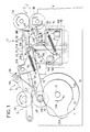
- FIG 1 there is schematically illustrated an automatic mail processing machine equipped with a device for selective wetting of the envelope flap, according to the present invention.
- the machine ensures, as desired, the closing of the envelopes whose flap has previously been moistened or the non-closing of the envelopes whose flap has then not been moistened.
- the wetting device is generally designated by the reference 1.
- the wetting device 1 is mounted on a path 2 of the machine casings. This path 2 is illustrated by a dashed line.
- the envelopes are driven on this path 2 by two pairs of sets of rollers 3A, 3B and 4A, 4B; the wetting device 1 is between these two pairs of rollers.
- Path 2 is defined by these pebble sets.
- the sets of lower rollers 3B and 4B are resiliently biased towards the sets of upper rollers 3A, 4A; they protrude above the level of path 2 in the absence of an envelope between them and the sets of upper rollers.
- the pair of upstream roller sets 3A, 3B belongs to a device 3 for loading the envelopes. Between its two sets of rollers, it receives each envelope to be loaded, maintains it during loading and, once loaded, advances it on path 2.
- the pair of downstream roller sets 4A, 4B contributes with the previous pair to maintaining and driving each envelope on the path 2. It also constitutes an ejection device 4 of each envelope loaded and closed if desired, from the path 2.
- the arrow 2A translates the advance of the envelopes on the path 2, through the wetting device 1, whether wetting their flap is desired or not desired.
- Each envelope advances flat on path 2, with its body at the front and its flap unfolded at the back.
- a device 5 for closing the envelopes is mounted between the wetting device and the ejection device 4.
- This closing device 5 comprises a pair of pressing elements 5A and 5B for closing the envelopes. They are mounted elastically under pressure one against the other, substantially at the end of a pair of arms 6 articulated opposite the pressing elements which it carries.
- the upper element 5A is a roller
- the lower element 5B is an elongated section profile.
- This pair of closing elements is made to pivot opposite path 2, between a rest position, which is that shown and in which it is erased above path 2, and a so-called closing position. In this closed position, it is interposed on path 2, with its two elements 5A, 5B on either side of the path.
- the arrow 6A translates the actuation of the pair of closing elements, from its rest position to its closed position, when the flap of the envelope to be closed is at its level on path 2.
- rollers 3A and 4A which are driven in one direction or the other at the appropriate moments to advance or retract each envelope. To this end, they are coupled to a reversible motor, not shown. An unreferenced double arrow is associated with them to translate their training in one direction or the other.
- the device for selective wetting of the envelope flap is described with reference to this FIG. 1, in particular for its general organization in the machine, and to FIGS. 2 and 3 in particular for its detailed embodiment. It comprises a mooring assembly 1A mounted under the track and an associated mooring deflector 1B mounted above the track.
- a wetting element 10 supplied with water from a tank 11.
- the wetting element 10 is mounted on a support 12 itself mounted on the tank 11. It projects above the tank 11 and extends transversely to the path 2, over its width, remaining slightly recessed under the path 2.
- the tank is closed by a cover 13 through which the wetting element passes.
- a series of fins 13A extends along the rear edge of the wetting element, considering the direction of advance of the envelopes given by arrow 2A. The fins protrude above the level of the mooring element to come out slightly on the level of path 2. They materialize path 2, just behind the mooring element, where they constitute a clear part pathway 2.
- the container 11 is mounted under the path 2, directly between two lower flanges, such as the primed flange 8, which define the lower part of the mail processing machine ( Figure 1). It is fixed on these flanges, whether the wetting operation is desired or not, and is easy to mount in the machine.
- each flange 8 has a notch 8A, substantially the width of the tray.
- Two projecting fingers 14A and 14B are provided identically on each of the small lateral faces of the tank, in the vicinity of two opposite corners.
- a support piece 9 is attached internally on each of the flanges; it defines two housings 9A, 9B of retaining fingers 14A, 14B.
- the tray 11 is mounted directly between the flanges on their support part 9. This mounting is done by tilting the tray, to first insert the lower finger 14B of each face into its housing 9B, then sliding the upper finger into its own housing 9A, while bringing the tank horizontally. This tray is then kept without play between the flanges; it can be removed just as easily.
- This support piece 9 is provided for ease of making the machine, but the retaining housings of the tray can alternatively be formed directly on the edges of the notch 8A of each flange.
- the wetting element 10 is flat. It is constituted for example by a flat felt, a flat sponge, a flat brush, or the like. It is mounted vertically in the tank, its lower part soaks in the water reserve, its upper part projects above the tank and of the cover, substantially up to the level of the path 2. Its support 12 has the form of a simple holding plate against which the element 10 is joined against one of its large faces; the support is kept in the tank by suitable means.
- This wetting element may alternatively be constituted by a wetting roller whose axis is retained on the tank; this roller partially dips directly in the water of the tank 11 or is supplied with water from the tank, by an intermediate supply roller or any other equivalent means.
- the wetting device 1 comprises, in addition in the assembly 1A, a sliding bar 15 associated with the wetting element 10. It extends transversely to the path 2, below the path and over its width; it is mounted on the tank 11 at the front of the wetting element 10, considering the direction of advance of the envelopes, and over its length. It is formed by a part with a high sliding coefficient for the envelopes. Its face facing the path 2 designated by the reference 15B is called sliding face; it is substantially linear. In the rest position of the wetting device 1 (FIG. 1), the sliding face 15B is just in front of the wetting element 10; she is slightly above the wetting element and substantially in the plane of path 2.
- the sliding bar 15 is also carried by the container 11. It is mounted at the end of a pair of arms 16.
- the arms 16 are articulated on the outside of the small lateral faces of the container, each around the projecting finger 14A, the further back on each small side face of the tank.
- the sliding bar 15 is thus pivoted, according to arrow 15A, in front of the wetting element 10, around the axis defined by the projecting fingers 14A, from a high rest position, for the position of rest or non-wetting of the device 1 (FIG. 1), at a low position which is called the erasure position of the bar or wetting of the device 1 (FIG. 2).
- a spring 17 is fixed on each arm 16 and the corresponding small side face of the tank. It urges each arm to maintain the elastic of the bar in its high rest position.
- This high rest position is called the protective position, in particular for the flexible flaps of the envelopes which it retains to avoid any possible contact with the wetting element 10, when their wetting is not desired. In this high position, it also ensures, with the fins 13A, the maintenance of the body of each envelope when it advances along arrow 2A through the wetting device, for its protection by avoiding any possible contact with the element of wetting, including during the envelope loading operation.
- the sliding bar has two drooping lips 15C, on the front edge of its face 15B for the envelopes advancing along arrow 2A.
- These lips 15C are substantially symmetrical with respect to the middle of the front edge of the bar. They facilitate the arrival, body at the front, of each envelope on the sliding bar in the high rest position.
- the sliding bar has, in addition, end portions 15D which protrude above the sliding face 15B and project beyond laterally on path 2.
- FIGS. 3A to 3C show that the end portions 15D are semi-round and that the bar 15 is moreover of section substantially in inverted V, of which a first of the branches defines the sliding face 15B and the second branch, not referenced, is attached to the end of the pair of arms 16 and is fixed thereto; each lip 15C comes from the first branch made, for the most part, longer.
- two lateral studs 18A, 18B, on each small lateral face of the tank, constitute stops for each arm 16, for the high protective position and the low erasing position of the slide bar 15, respectively.
- Figures 1 and 2 show that in the wetting device 1, the wetting deflector 1B comprises a deflector proper 20. It is mounted above the path 2, being slightly in front of the wetting element 10 for cooperate with it and with the slide bar 15 with which it is associated and adapted.
- the deflector 20 extends transversely to the path 2. It is mounted substantially at the end of a pair of arms 21.
- the arms 21 extend laterally on the path 2. They are articulated around an intermediate axis 21A situated above of path 2. Their end part opposite the deflector 20 comes under the level of path 2. It carries a roller 21B which is supported on a corresponding wetting control cam 22.
- the deflector 20 is thus pivoted around of the axis 21A, from a rest position which is that of non-wetting to a working position which is that of wetting. In its rest position, it is at a distance above the level of the path 2 and allows free passage, between it and the sliding bar 15 and the wetting element 10, the successive envelopes.
- An arrow 20A translates the control of the deflector 20 from its rest position to that of wetting.
- the deflector 20 is shown in solid lines in its wetting position and is sketched in dotted lines in its rest position.
- the cam 7 for closing the envelopes and the cam 22 for wetting control are advantageously mounted on the same control shaft 23.
- This control shaft is driven according to the arrow 23A by a control motor, not illustrated, in synchronism with the progress of the successive stages of a control cycle of the machine.
- the cams 7 and 22 are shown, for the rest position of the machine, in a reference position detected by an optical sensor not shown. They are driven on a complete revolution for each cycle with or without wetting and in corresponding closing or non-closing of the envelope concerned.
- a first section 7A is assigned to the maintenance in the rest position of the pair of closing elements 5A, 5B, while a second section 7B is assigned to the maintenance in the closed position of these same elements.
- a profile 22A is assigned to keeping the wetting deflector 20 in the rest position and a profile 22B to keeping it in the wetting position.
- the cams 7 and 22 are set relatively to one another, with all of the section 22B for holding the wetting deflector 20 in the wetting position having a slight advance on the section 7B for holding the closing elements 5A, 5B in the closed position.
- the wetting deflector 20 when wetting of the flap is desired, the wetting deflector 20 is in the wetting position while the closing elements remain in the rest position. The wetting deflector 20 returns to the rest position by the profile 22A while the closing elements 5A, 5B will pass into the closed position.
- the wetting deflector 20 and the closing elements 5A, 5B remain in the rest position, by the sections 22A and 7A throughout the duration of presence and total passage of the 'envelope at their level.
- the roller 21B remains on the profile 22A until the unclosed envelope is ejected. After this ejection, the shaft 23 is driven at the end of the rotation turn for this cycle until return of the cams to their detected reference position.
- the mooring deflector 20 is produced by a profile, of section having substantially the shape of a U, which is fixed between the pair of arms 21. Its lower face is inclined at an angle above the path and is opposite the bar sliding 15, when the latter is in its rest position.
- the deflector is then, as can be seen from FIG. 1, above and slightly in front of the wetting element 10 and allows the envelopes to pass freely between it and the bar in the high protective position.
- the envelope flaps despite their flexibility, absolutely cannot come into contact with the wetting element, when they pass through these wetting devices.
- the front edge 20B and the rear edge 20C (FIG. 2) of the underside of the deflector 20 are both rounded, with the front edge of radius curvature greater than that of the rear edge.
- the deflector 20 When the deflector 20 is in the wetting position and the slide bar 15 in its erasing position, as shown in FIG. 2, the deflector 20 largely interferes with the level of the path 2, then simply materialized by the upper edge of the wetting element 10 and the fins 13A at the rear.
- the front edge 20B On its underside, which cuts the path at an angle, the front edge 20B constitutes upstream means for guiding the flap under the level of the front edge of the wetting element, the rear edge 20C constitutes means for applying the flap against the wetting element.
- This rear edge 20C, below the level of the path 2 is just in front of the wetting element 10; it then leaves, between itself and the wetting element, only a very small gap.
- the deflector causes the flap to be wetted without fail.
- the deflector by its front edge then its lower surface, guides the flexible flap to bend it strongly below the level of the path before letting it pass between its rear edge and the wetting element. By its rear edge, it forces the flap under pressure against the wetting element, for satisfactory but not excessive wetting.
- the heads of the fins 13A, on which then rubs, without pressure, the moistened face of the flaps, do not in any way harm the quality of the wetting which has just been ensured.
- the wetting deflector 20 is mounted resiliently opposite the path 2. To this end, a certain elasticity is given to the arms 21 which carry and control it, as shown in Figure 1.
- each of the arms 21 is constituted by an actual control lever 24, carrying the roller 21B and articulated around the axis 21A, and an actual support arm 25, carrying the deflector 20 and also articulated around axis 21A.
- This lever 24 and the support arm 25 are also resiliently held relative to each other by a spring 26.
- the end of the control lever 24, opposite the roller 21B defines a ramp 24A d support for the support arm 25.
- the latter has in correspondence a rib 25A projecting transversely on it and resting on the support ramp 24A.
- the spring 26 is fixed on the control lever 24 and on the rib 25A of the support 25, it tends to keep the rib 25A in abutment on the ramp 24A, while allowing additional possible movement of the support arm 25 around the axis 21A, depending on the thickness of the envelope present under the deflector 20.
- the actuation of the sliding bar 15 from its protective position to its erasing position, according to arrow 15A, is ensured at the same time as the actuation of the deflector 20 from its rest position to its wetting position, according to arrow 20A, It advantageously comes directly from the control of the deflector 20.
- each arm 21, or more precisely of each support arm 25 on which the deflector 20 is fixed is of a shape adapted to directly ensure the action ment of the sliding bar in the erasing position, against the action of the spring 17.
- This end of the support arm 25 forms a pressing element 25D for the semi-circular end portion 15D of the sliding bar, said to correspond in abutment stop for the pressing element 25D.
- the sliding bar 15 When the wetting deflector 20 is in the rest position, the sliding bar 15 is in the high protective position; the pressing element 25D is then substantially in contact with the corresponding support stop 15D, but exerts no pressure on it.
- the pressing element 25D acts on the corresponding abutment stop 15D, with its lower edge sliding on the circular surface of this abutment , and drives the sliding bar, according to arrow 15A, against the action of the spring 17.
- the spring 17 allows in return the return of the sliding bar in its protective position.
- the wetting device is particularly simple to make and control. It is also simple and very safe to operate. Its elements are made of plastic and each from molding.
- the deflector can be constituted by a substantially semi-circular profile, on which is elastically mounted an element or a series of elements, extending towards the rear the effect of the semi-circular lower edge of such a profile. for proper application of the flap against the wetting element.
Landscapes
- Making Paper Articles (AREA)
- Air Humidification (AREA)
- Package Closures (AREA)
- Basic Packing Technique (AREA)
- Feeding Of Articles By Means Other Than Belts Or Rollers (AREA)
Applications Claiming Priority (2)
| Application Number | Priority Date | Filing Date | Title |
|---|---|---|---|
| FR8912706 | 1989-09-28 | ||
| FR8912706A FR2652307B1 (fr) | 1989-09-28 | 1989-09-28 | Dispositif de mouillage selectif de rabat d'enveloppes. |
Publications (2)
| Publication Number | Publication Date |
|---|---|
| EP0420111A1 true EP0420111A1 (de) | 1991-04-03 |
| EP0420111B1 EP0420111B1 (de) | 1994-03-16 |
Family
ID=9385904
Family Applications (1)
| Application Number | Title | Priority Date | Filing Date |
|---|---|---|---|
| EP90118318A Expired - Lifetime EP0420111B1 (de) | 1989-09-28 | 1990-09-24 | Anpassbare Befeuchtungsvorrichtung für Briefklappen |
Country Status (4)
| Country | Link |
|---|---|
| US (1) | US5088442A (de) |
| EP (1) | EP0420111B1 (de) |
| DE (1) | DE69007394T2 (de) |
| FR (1) | FR2652307B1 (de) |
Cited By (3)
| Publication number | Priority date | Publication date | Assignee | Title |
|---|---|---|---|---|
| EP0540292A1 (de) * | 1991-10-28 | 1993-05-05 | Pitney Bowes Inc. | Postmaschine mit einer Vorrichtung zum selektiven Befeuchten und Verschliessen von Umschlägen |
| EP0587362A1 (de) * | 1992-08-31 | 1994-03-16 | Pitney Bowes Inc. | Vorrichtung zum Auswerfen von Briefen für Kuvertiermaschine |
| EP0631885A1 (de) * | 1993-07-02 | 1995-01-04 | Pitney Bowes Inc. | Anfeuchteinrichtung für Briefklappen |
Families Citing this family (7)
| Publication number | Priority date | Publication date | Assignee | Title |
|---|---|---|---|---|
| US5489358A (en) * | 1991-10-28 | 1996-02-06 | Pitney Bowes Inc. | Mailing machine including apparatus for selectively moistening and sealing envelopes |
| US5217551A (en) * | 1991-10-28 | 1993-06-08 | Pitney Bowes Inc. | Mailing machine including a process for selectively moistening envelopes fed thereto |
| US5314566A (en) * | 1992-12-17 | 1994-05-24 | Pitney Bowes Inc. | Mailing machine including low speed sheet feeding and jam detection structure |
| GB0202243D0 (en) * | 2002-01-31 | 2002-03-20 | Neopost Ltd | Moistener for a mailing machine |
| US7425244B2 (en) * | 2005-10-07 | 2008-09-16 | Pitney Bowes Inc. | Moistening device for sealing envelope flaps |
| EP2213474B1 (de) * | 2009-01-30 | 2014-03-12 | Neopost Technologies | Umschlagklappenanfeuchter |
| CN110801994A (zh) * | 2019-11-20 | 2020-02-18 | 象山锐文智能装备有限公司 | 一种用于中央处理器表面硅脂涂抹机 |
Citations (8)
| Publication number | Priority date | Publication date | Assignee | Title |
|---|---|---|---|---|
| US1529164A (en) * | 1924-03-29 | 1925-03-10 | Cardwell Thomas | Machine for mechanically sealing envelopes and the like |
| US1866452A (en) * | 1927-08-03 | 1932-07-05 | Cogswell Alexander Gordon | Apparatus for folding paper, inserting it in envelopes, tucking in the flap or sealing the envelopes, and stamping them |
| FR1244099A (fr) * | 1959-04-23 | 1960-10-21 | Bafra Maschinen Ges M B H | Machine à cacheter les lettres |
| US3168428A (en) * | 1961-11-16 | 1965-02-02 | Reuben R Logan | Apparatus for sealing envelopes |
| DE2320484A1 (de) * | 1973-04-21 | 1974-11-07 | Postalia Gmbh | Briefschliesseinrichtung fuer frankiermaschinen |
| EP0100674A2 (de) * | 1982-08-04 | 1984-02-15 | Xerox Corporation | Vorrichtung und Verfahren zur Versiegelung von Briefumschlägen |
| US4450037A (en) * | 1983-06-22 | 1984-05-22 | Pitney Bowes Inc. | Envelope flap sealing device |
| EP0319888A1 (de) * | 1987-12-11 | 1989-06-14 | Alcatel Satmam | Vorrichtung zum Falten der Klappen von Briefumschlägen |
-
1989
- 1989-09-28 FR FR8912706A patent/FR2652307B1/fr not_active Expired - Lifetime
-
1990
- 1990-09-20 US US07/585,453 patent/US5088442A/en not_active Expired - Lifetime
- 1990-09-24 EP EP90118318A patent/EP0420111B1/de not_active Expired - Lifetime
- 1990-09-24 DE DE69007394T patent/DE69007394T2/de not_active Expired - Fee Related
Patent Citations (8)
| Publication number | Priority date | Publication date | Assignee | Title |
|---|---|---|---|---|
| US1529164A (en) * | 1924-03-29 | 1925-03-10 | Cardwell Thomas | Machine for mechanically sealing envelopes and the like |
| US1866452A (en) * | 1927-08-03 | 1932-07-05 | Cogswell Alexander Gordon | Apparatus for folding paper, inserting it in envelopes, tucking in the flap or sealing the envelopes, and stamping them |
| FR1244099A (fr) * | 1959-04-23 | 1960-10-21 | Bafra Maschinen Ges M B H | Machine à cacheter les lettres |
| US3168428A (en) * | 1961-11-16 | 1965-02-02 | Reuben R Logan | Apparatus for sealing envelopes |
| DE2320484A1 (de) * | 1973-04-21 | 1974-11-07 | Postalia Gmbh | Briefschliesseinrichtung fuer frankiermaschinen |
| EP0100674A2 (de) * | 1982-08-04 | 1984-02-15 | Xerox Corporation | Vorrichtung und Verfahren zur Versiegelung von Briefumschlägen |
| US4450037A (en) * | 1983-06-22 | 1984-05-22 | Pitney Bowes Inc. | Envelope flap sealing device |
| EP0319888A1 (de) * | 1987-12-11 | 1989-06-14 | Alcatel Satmam | Vorrichtung zum Falten der Klappen von Briefumschlägen |
Cited By (3)
| Publication number | Priority date | Publication date | Assignee | Title |
|---|---|---|---|---|
| EP0540292A1 (de) * | 1991-10-28 | 1993-05-05 | Pitney Bowes Inc. | Postmaschine mit einer Vorrichtung zum selektiven Befeuchten und Verschliessen von Umschlägen |
| EP0587362A1 (de) * | 1992-08-31 | 1994-03-16 | Pitney Bowes Inc. | Vorrichtung zum Auswerfen von Briefen für Kuvertiermaschine |
| EP0631885A1 (de) * | 1993-07-02 | 1995-01-04 | Pitney Bowes Inc. | Anfeuchteinrichtung für Briefklappen |
Also Published As
| Publication number | Publication date |
|---|---|
| US5088442A (en) | 1992-02-18 |
| EP0420111B1 (de) | 1994-03-16 |
| DE69007394T2 (de) | 1994-06-23 |
| FR2652307B1 (fr) | 1991-11-29 |
| DE69007394D1 (de) | 1994-04-21 |
| FR2652307A1 (fr) | 1991-03-29 |
Similar Documents
| Publication | Publication Date | Title |
|---|---|---|
| EP0352692B1 (de) | Integrierte Büromaschine zum Falten und Kuvertieren von Poststücken | |
| EP0420111B1 (de) | Anpassbare Befeuchtungsvorrichtung für Briefklappen | |
| EP0102301B1 (de) | Maschine und Arbeitsweise zum Herstellen von Kunststoffbeuteln mit Reissverschluss und Vorrichtung zum Anbringen desselben | |
| EP0352693B1 (de) | Vorrichtung zum Schliessen von Briefen | |
| FR2787416A1 (fr) | Dispositif pour la pose en continue de poignees autocollantes sur des objets, paquets ou lots | |
| EP0352686B1 (de) | Vorrichtung zum Öffnen und Füllen von Briefumschlägen | |
| EP0352687B1 (de) | Brieffülleinrichtung | |
| EP0420110B1 (de) | Befeuchtigungsvorrichtung für Gegenstände, als Teil einer Einrichtung und ihre Anwendung | |
| EP0300871B1 (de) | Mischmaschine für Teigmaterial, insbesondere für Brotteig | |
| EP0398823A1 (de) | Schneidevorrichtung für einen automatischen Spender von Aufwischmaterial, das aus schmalen, im Zickzack gefaltenen Bändern besteht | |
| EP0334277B1 (de) | Bindemaschine für Stapel von Bögen | |
| EP0301983A1 (de) | Vorrichtung zum Aufbringen eines den Abstandshalter zwischen den Glasscheiben einer rechteckigen oder quadratischen Doppelverglasung bildenden Stranges | |
| EP1145196B1 (de) | Vorrichtung zur ausgabe von karten | |
| EP1261496B1 (de) | Briefschliessvorrichtung für eine postmaschine | |
| EP0297501B1 (de) | Frankiermaschine mit einer Wahlweise arbeitenden Ausgabe für entweder trockene oder aufgefeuchtete, bedruckte Etiketten | |
| FR2483269A1 (fr) | Ouvreur de bobine | |
| FR2598943A1 (fr) | Tete de travail pour appareil de nettoyage par epandage d'un liquide de nettoyage et aspiration des saletes | |
| EP0319888B1 (de) | Vorrichtung zum Falten der Klappen von Briefumschlägen | |
| CA2001841A1 (fr) | Procede pour l' emballage d'objets et machine pour la mise en oeuvre de ce procede | |
| EP0581690A1 (de) | Kartonverschliessmaschine zum Anbringen eines gummierten Bandes | |
| EP0052057B1 (de) | Verfahren und Vorrichtung zum Überziehen einer Ladung mit einer Schlauchfolie | |
| FR2637253A1 (fr) | Machine pour le conditionnement sous vide de produits alimentaires ou autres dans des barquettes d'emballage | |
| CH137905A (fr) | Machine automatique pour coller des bandes de papier. | |
| FR2576319A1 (fr) | Perfectionnements aux machines a remplier le cuir | |
| FR2588220A1 (fr) | Organe de prise de contact pour perche de trolley-bus |
Legal Events
| Date | Code | Title | Description |
|---|---|---|---|
| PUAI | Public reference made under article 153(3) epc to a published international application that has entered the european phase |
Free format text: ORIGINAL CODE: 0009012 |
|
| AK | Designated contracting states |
Kind code of ref document: A1 Designated state(s): DE FR GB NL |
|
| 17P | Request for examination filed |
Effective date: 19910924 |
|
| RAP1 | Party data changed (applicant data changed or rights of an application transferred) |
Owner name: NEOPOST INDUSTRIE |
|
| 17Q | First examination report despatched |
Effective date: 19930426 |
|
| GRAA | (expected) grant |
Free format text: ORIGINAL CODE: 0009210 |
|
| AK | Designated contracting states |
Kind code of ref document: B1 Designated state(s): DE FR GB NL |
|
| REF | Corresponds to: |
Ref document number: 69007394 Country of ref document: DE Date of ref document: 19940421 |
|
| GBT | Gb: translation of ep patent filed (gb section 77(6)(a)/1977) |
Effective date: 19940329 |
|
| PLBE | No opposition filed within time limit |
Free format text: ORIGINAL CODE: 0009261 |
|
| STAA | Information on the status of an ep patent application or granted ep patent |
Free format text: STATUS: NO OPPOSITION FILED WITHIN TIME LIMIT |
|
| 26N | No opposition filed | ||
| REG | Reference to a national code |
Ref country code: GB Ref legal event code: IF02 |
|
| PGFP | Annual fee paid to national office [announced via postgrant information from national office to epo] |
Ref country code: GB Payment date: 20050822 Year of fee payment: 16 |
|
| PGFP | Annual fee paid to national office [announced via postgrant information from national office to epo] |
Ref country code: DE Payment date: 20050921 Year of fee payment: 16 |
|
| PGFP | Annual fee paid to national office [announced via postgrant information from national office to epo] |
Ref country code: NL Payment date: 20050927 Year of fee payment: 16 |
|
| PG25 | Lapsed in a contracting state [announced via postgrant information from national office to epo] |
Ref country code: NL Free format text: LAPSE BECAUSE OF NON-PAYMENT OF DUE FEES Effective date: 20070401 |
|
| PG25 | Lapsed in a contracting state [announced via postgrant information from national office to epo] |
Ref country code: DE Free format text: LAPSE BECAUSE OF NON-PAYMENT OF DUE FEES Effective date: 20070403 |
|
| GBPC | Gb: european patent ceased through non-payment of renewal fee |
Effective date: 20060924 |
|
| NLV4 | Nl: lapsed or anulled due to non-payment of the annual fee |
Effective date: 20070401 |
|
| PG25 | Lapsed in a contracting state [announced via postgrant information from national office to epo] |
Ref country code: GB Free format text: LAPSE BECAUSE OF NON-PAYMENT OF DUE FEES Effective date: 20060924 |
|
| PGFP | Annual fee paid to national office [announced via postgrant information from national office to epo] |
Ref country code: FR Payment date: 20080912 Year of fee payment: 19 |
|
| REG | Reference to a national code |
Ref country code: FR Ref legal event code: ST Effective date: 20100531 |
|
| PG25 | Lapsed in a contracting state [announced via postgrant information from national office to epo] |
Ref country code: FR Free format text: LAPSE BECAUSE OF NON-PAYMENT OF DUE FEES Effective date: 20090930 |