EP0420209B1 - Appareil d'enregistrement/reproduction - Google Patents
Appareil d'enregistrement/reproduction Download PDFInfo
- Publication number
- EP0420209B1 EP0420209B1 EP90118500A EP90118500A EP0420209B1 EP 0420209 B1 EP0420209 B1 EP 0420209B1 EP 90118500 A EP90118500 A EP 90118500A EP 90118500 A EP90118500 A EP 90118500A EP 0420209 B1 EP0420209 B1 EP 0420209B1
- Authority
- EP
- European Patent Office
- Prior art keywords
- recording
- signal
- level
- area
- reproducing
- Prior art date
- Legal status (The legal status is an assumption and is not a legal conclusion. Google has not performed a legal analysis and makes no representation as to the accuracy of the status listed.)
- Expired - Lifetime
Links
- 230000003287 optical effect Effects 0.000 claims description 92
- 238000001514 detection method Methods 0.000 claims description 17
- 238000006243 chemical reaction Methods 0.000 claims 2
- 239000004065 semiconductor Substances 0.000 description 13
- 238000010586 diagram Methods 0.000 description 6
- 239000010410 layer Substances 0.000 description 4
- 230000004044 response Effects 0.000 description 3
- 230000003321 amplification Effects 0.000 description 2
- 239000003990 capacitor Substances 0.000 description 2
- 238000004519 manufacturing process Methods 0.000 description 2
- 238000003199 nucleic acid amplification method Methods 0.000 description 2
- 239000000758 substrate Substances 0.000 description 2
- 229910052797 bismuth Inorganic materials 0.000 description 1
- JCXGWMGPZLAOME-UHFFFAOYSA-N bismuth atom Chemical compound [Bi] JCXGWMGPZLAOME-UHFFFAOYSA-N 0.000 description 1
- 239000011247 coating layer Substances 0.000 description 1
- 239000000428 dust Substances 0.000 description 1
- 230000005669 field effect Effects 0.000 description 1
- 239000011521 glass Substances 0.000 description 1
- 229910052751 metal Inorganic materials 0.000 description 1
- 239000002184 metal Substances 0.000 description 1
- 239000000725 suspension Substances 0.000 description 1
- 229910052714 tellurium Inorganic materials 0.000 description 1
- PORWMNRCUJJQNO-UHFFFAOYSA-N tellurium atom Chemical compound [Te] PORWMNRCUJJQNO-UHFFFAOYSA-N 0.000 description 1
Images


Classifications
-
- G—PHYSICS
- G11—INFORMATION STORAGE
- G11B—INFORMATION STORAGE BASED ON RELATIVE MOVEMENT BETWEEN RECORD CARRIER AND TRANSDUCER
- G11B7/00—Recording or reproducing by optical means, e.g. recording using a thermal beam of optical radiation by modifying optical properties or the physical structure, reproducing using an optical beam at lower power by sensing optical properties; Record carriers therefor
- G11B7/12—Heads, e.g. forming of the optical beam spot or modulation of the optical beam
- G11B7/125—Optical beam sources therefor, e.g. laser control circuitry specially adapted for optical storage devices; Modulators, e.g. means for controlling the size or intensity of optical spots or optical traces
- G11B7/126—Circuits, methods or arrangements for laser control or stabilisation
Definitions
- the present invention relates to a recording/reproducing system, and, more particularly, to an optical disk apparatus which optically records data on tracks on an optical disk, or reads recorded data therefrom by rotating the optical disk in relation to an optical head.
- Image filing systems use an optical disk apparatus, which records data on spiral or concentric tracks formed on an optical disk or reproduces recorded data therefrom while rotating the optical disk.
- An original is two-dimensionally scanned so that its image data is photoelectrically converted into electric image data.
- the electric image data is optically recorded on the tracks of the optical disk by an optical head.
- the recorded data is retrieved by the optical head at the time of retrieval and is reproduced as a hard copy or soft copy.
- the optical disk apparatus performs data writing or data reading with a laser beam produced by a semiconductor laser oscillator provided in the optical head.
- the specifications of usable optical disks such as the reflection factor, the laser powers required for data writing and data reading, and the number of sectors around the optical disk, are fixed.
- optical disks with different specifications which are manufactured by various companies. If optical disks have different specifications mentioned above, they cannot generally be used in a single optical disk apparatus.
- an optical disk on which specifications data as mode data different for each manufacturer, or a so-called control track, is recorded for standardization is recorded in a specifications data recording area for specifications data, which is located inward of a data recording area where record data is to be recorded.
- Data of the specifications indicating the manufacturer of this optical disk is recorded in bar code on this control track.
- Each bar of the bar code consists of a group of pits arranged in rows and columns.
- control track Also recorded on the control track is data, such as the reflection factor, the laser powers required for data writing and data reading, and the number of sectors around the optical disk, in order to determine the reading/writing specifications.
- optical disks there are two types: rewritable optical disk which requires a high-power laser beam for data reading and write-once type optical disk which requires a low-power laser beam for data reading.
- rewritable optical disk which requires a high-power laser beam for data reading
- write-once type optical disk which requires a low-power laser beam for data reading.
- Prior art documents DE-A-3 830 745 and FR-A-2 575 857 disclose a disk recording/reproducing apparatus for recording information on an optical disk by means of a laser beam of a recording power-level, and reproducing recorded information from the optical disk by means of a laser beam of a reproducing power-level which is lower than the power level for recording.
- the optical disk has a recording layer selected from various types of recording layers including a first area in which information is recorded in and reproduced from, and a second area storing data representing the power levels for recording and reproducing in accordance with the type of the recording layer.
- the disk recording/reproducing apparatus further comprises a laser generator for generating laser beams of recording power-levels and laser beams of reproducing power-levels, and applying the laser beams to the recording layer.
- the laser generator is movable to the first and second areas, and caused to generate a specific laser beam of a level equal to the lowest reproducing power level when it is moved to the second area.
- a light detector detects light reflected from the second area and generates a detection signal.
- the power level to be generated by the laser generator is selected in accordance with the detection signal.
- the lower level detection signal is based on the interval between recorded portions of a signal read from the second area.
- the present invention provides a disk recording/reproducing system as specified in claim 1.
- Fig. 1 schematically illustrates one embodiment of an optical disk apparatus according to the present invention.
- An optical disk 1 shown in Fig. 1 has spiral or concentric grooves (tracks) formed on its surface.
- This optical disk 1 is driven at, for example, a constant speed (1800 rpm), by a motor 2 which is controlled by a motor controller 18.
- the optical disk 1 there are a rewritable type which requires a high-power laser beam of 1.5 mW for data reading and a write-one type which needs a low-power laser beam of 0.4 mW for the same purpose.
- a laser beam of 8 to 10 mW is used for data recording or erasing.
- the optical disk 1 comprises a glass or plastic, disk-shaped substrate with a diameter of, for example, 5.25 in (about 13.3 cm), and a metal coating layer or recording film, which is coated in doughnut shape on one surface of the substrate and is composed of tellurium or bismuth.
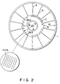
- the optical disk 1 as on its surface a data recording area 1a having tracks formed therein and a specifications data recording area 1b located inward of the former area 1a.
- the latter area 1b has no guide grooves formed therein.
- the data recording area 1a is divided into a plurality of sectors with a reference mark as its reference point.
- Data of a variable length is recordable over a plurality of blocks on the optical disk 1; there are 300,000 blocks formed on 36,000 tracks on the optical disk 1.
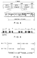
- a block header A as preformat data is recorded at the beginning of each block, a recording unit, at the time the optical disk 1 is manufactured.
- the block header A includes a block number and a track number.
- a control track C is likewise recorded at the time of manufacturing the optical disk 1.
- the same data is recorded three times for one revolution, in a bar code shape in the circumferential direction on the control track C.
- the specifications data includes the reflection factor as the film characteristic of the optical disk 1, the laser powers of a semiconductor laser oscillator required for data writing, data erasing and data reproduction, and the number of sectors around the optical disk as a format type.
- control track C indicates data in the form of consecutive or non-consecutive columns of bits, and is recorded radially in the radial direction of the optical disk 1.
- the recording position of the control track C is defined by the distance from the center of the optical disk 1 or the radial position thereof.
- control track C is recorded over a region from the position of the radius of 29.0 cm to the position of the radius of 29.3 cm.
- control track C consists of three sectors each including a gap, preamble, a sync signal, specifications data, sector/track address data and CRC check data.
- bit of data on the control track C it is determined to be bit "0" if consecutive 82 pits exist at the first half of the optical disk 1, and is considered to be bit "1" if consecutive 82 pits exist at the second half, as shown in Fig. 4.
- one bit of data on the control track C is determined to be bit "0" if plural columns of pits exist in 328 channel bits at the first half of the optical disk 1, and is considered to be bit "1" if plural columns of pits exist in 328 channel bits at the second half.
- An optical head 3 is disposed below the optical disk 1, close to the bottom thereof. As shown in Fig. 1, this optical head 3 comprises an objective lens 6, drive coils 4 and 5 for driving the objective lens 6, a photosensor 8, a semiconductor laser oscillator 9, a focusing lens 10a, a cylindrical lens 10b, a collimator lens 11a for collimating a laser beam from the laser oscillator 9, a half prism 11b and a light-receiving element PD for detecting the amount of light emitted from the laser oscillator 9.
- this optical head 3 comprises an objective lens 6, drive coils 4 and 5 for driving the objective lens 6, a photosensor 8, a semiconductor laser oscillator 9, a focusing lens 10a, a cylindrical lens 10b, a collimator lens 11a for collimating a laser beam from the laser oscillator 9, a half prism 11b and a light-receiving element PD for detecting the amount of light emitted from the laser oscillator 9.
- the objective lens 6 is suspended from a fixed portion (not shown) by a wire suspension. This objective lens 6 moves in the focusing direction or along the optical axis of the lens 6 when driven by the drive coil 5, and moves in the tracking direction or in the direction perpendicular to the optical axis of the lens 6 when driven by the drive coil 4.
- the optical head 3 is secured to a drive coil 13 serving as a movable portion of a linear motor 31.
- the drive coil 13 is connected to a linear motor controller 17 which is connected to a linear motor position detector 26.
- This position detector 26 detects an optical scale 25 provided at the optical head 3 and outputs a position signal.
- a permanent magnet (not shown) is provided so that when the drive coil 13 is excited by the linear motor controller 17, the laser beam from the optical head 3 moves in the radial direction of the optical disk 1 with the movement of the linear motor 31.
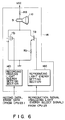
- the laser controller 14 In response to a command from a CPU 23 (to be described later), the laser controller 14 causes the semiconductor laser oscillator 9 to generate a high-power laser beam of 1.5 mW for data reading or a low-power laser beam of 0.4 mW for data reading. In response to a command from the CPU 23, the laser controller 14 permits the semiconductor laser oscillator 9 to generate a laser beam wit power of 8 to 10 mW for data recording or data erasing.
- the laser controller 14 comprises a setting section 14a for setting the amount or energy of reproducing light, a setting section 14b for setting the amount or energy of recording/erasing light, an NPN type transistor Ta, an FET (Field Effect Transistor) Tb, and resistors Ra and Rb.
- the reproducing light energy setting section 14a sends a drive signal, corresponding to a reproduction signal and a light energy select signal supplied from the CPU 23, to the base of the transistor Ta.
- the recording/erasing light energy setting section 14b outputs a control signal, associated with a modulation signal corresponding to record data from the CPU 23 at the time of data recording, to the gate of the FET Tb.
- This section 14b also outputs a control signal, supplied from the CPU 23 at the time of data erasing, to the gate of the FET Tb.
- a current is amplified by an amplification factor corresponding to the drive signal from the setting section 14a.
- different currents flow through the semiconductor laser oscillator 9 so that the laser oscillator 9 generates a high-power laser beam of 1.5 mW for data reading and a low-power laser beam of 0.4 mw for data reading accordingly.
- the FET Tb is rendered on or off by the control signal supplied from the setting section 14b.
- the FET Tb when turned on, permits a current to flow to the semiconductor laser oscillator 9 which in turn generates a laser beam with power of 8 to 10 mW.
- the emitter of the transistor Ta and the drain of the FET Tb are both connected to a voltage source (V CC ) through the semiconductor laser oscillator 9 and resistor Ra.
- the transistor Ta has its collector grounded through the resistor Rb, and the FET Tb has it source grounded.
- the photosensor 8 comprises four photosensor cells 8a, 8b, 8c and 8d, as shown in Fig. 1.
- the output signal of the photosensor cell 8a is supplied via an amplifier 12a to one end of an adder 30a as well as one end of an adder 30c.
- the output signal of the photosensor cell 8b is supplied via an amplifier 12b to one end of each of adders 30b and 30d.
- the output signal of the photosensor cell 8c is supplied via an amplifier 12c to the other end of each of the adders 30b and 30c.
- the output signal of the photosensor cell 8d is supplied via an amplifier 12d to the other end of each of the adders 30a and 30d.
- the output signal of the adder 30a is supplied to an inverting input terminal of a differential amplifier OP1 whose non-inverting input terminal is supplied with the output signal of the adder 30b.
- the differential amplifier OP1 sends a track difference signal corresponding to the difference between the outputs of the adders 30a and 30b, to a tracking controller 16.
- the tracking controller 16 prepares a track drive signal in accordance with the track difference signal from the differential amplifier OP1.
- the track drive signal from the tracking controller 16 is sent to the drive coil 4 that moves the objective lens in the tracking direction.
- the track difference signal used in the tracking controller 16 is sent to the linear motor controller 17.
- the output signal of the adder 30c is supplied to an inverting input terminal of a differential amplifier OP2 whose non-inverting input terminal is supplied with the output signal of the adder 30d.
- the differential amplifier OP2 sends a signal associated with the focus point and corresponding to the difference between the outputs of the adders 30c and 30d, to a focusing controller 15.
- the output signal of this focusing controller 15 is supplied to the focusing drive coil 5, so that the laser beam is controlled to be always just in focus on the optical disk 1.
- a signal representing the sum of the outputs of the individual photosensor cells 8a to 8d of the photosensor 8, or the output signals of the adders 30a and 30b reflect the upheaval statuses of the pits (recorded data) formed on the tracks.
- These signal are supplied to a video circuit 19 which reproduces image data and address data (track number, sector number, etc.).
- a binary signal reproduced by this video circuit 19 is output via an interface circuit 70 to an optical disk controller 71.
- the output signals of the adders 30a and 30b are supplied to a control track read circuit 32.
- the circuit 32 outputs count values as time intervals corresponding to the recorded portion corresponding to the recorded data on the control track C and the unrecorded portion.
- the count values of the control track read circuit 32 are sent to the CPU 23 (which will be described later).
- the CPU 23 causes the optical head 3 to move from the innermost track on the optical disk 1.
- the CPU 23 determines that the optical head 3 is positioned at the vicinity of the center of the control track C, and stops the optical head 3.
- the CPU 23 checks the count values supplied from input ports 51 and 52 (to be described later) of the control track read circuit 32, i.e., the time intervals of the recorded portion and unrecorded portion, to read out the specifications data on the control track C, and performs an operational control in accordance with this specifications data.
- this apparatus is controlled in association with different optical disks 1 having different specifications (companies).
- This optical disk apparatus employs a D/A converter 22 to ensure data exchange between the CPU 23 and the focusing controller 15, tracking controller 16 or linear motor controller 17.
- the tracking controller 16 moves the objective lens 6 to shift the laser beam by one track in accordance with a track jump signal supplied via the D/A converter 22 from the CPU 23.
- the laser controller 14, focusing controller 15, tracking controller 16, linear motor controller 17, motor controller 18, and the video circuit 19 are controlled via a bus line 20 by the CPU 23. These units are controlled by a program stored in a memory 24 under the control of the CPU 23.
- control track read circuit 32 comprises an adder circuit 32a, a low-level detector 32b, a binary value producing circuit 32c and a time interval counting section 32d.
- the lower-level detector 32b comprises a diode D1, an integrator constituted of a capacitor C1 and an amplifier 33.
- the binary value producing circuit 32c comprises diodes D2 and D3, a resistor R1, a capacitor C2 and a comparator 34.
- the time interval counting section 32d comprises a sync circuit 40, an output switching timing circuit 41, clear signal generators 42 and 43, recorded-portion measuring counter 44, an unrecorded-portion measuring counter 45, an inverter circuit 46, an OR circuit 47, flip-flop circuits (FF circuits) 48 and 49, a switch 50, and input ports 51 and 52.
- the adder circuit 32a adds the output signals of the adders 30a and 30b and outputs a reproduction signal r corresponding to the sum of detection signals of the photosensor cells 8a to 8d.
- the lower-level detector 32b detects the lower-level of the reproduction signal r from the adder circuit 32a and produces a lower-level detection signal 1 which is a signal resulting from the detection of the peak of the dark level of the reproduction signal r.
- the comparator 34 of the binary value production circuit 32c compares the lower-level detection signal 1 from the lower-level detector 32b with a delay signal d which is acquired by delaying the former signal 1.
- the comparator 34 If the delay signal d is smaller than the lower-level detection signal 1, the comparator 34 outputs an "H"-level signal or a signal corresponding to the recorded portion. Accordingly, a binary signal t corresponding to the recorded data on the control track C is output to the time interval counting section 32d.
- the lower-level detection signal 1 as shown in Fig. 8B is detected from the reproduction signal r as shown in Fig. 8A and the binary signal t as shown in Fig. 8C is acquired by comparing the first two signals 1 and d with each other.
- the time interval counting section 32d detects a blank gap based on the binary signal t from the binary value producing circuit 32c, and the number of counts of the recorded portion and unrecorded portion following this blank gap is output to the CPU 23.
- the sync circuit 40 synchronizes the binary signal t from the binary value producing circuit 32c with a clock from an oscillator (not shown), and sends its output to the output switching timing circuit 41, clear signal generators 42 and 43, recorded-portion measuring counter 44 and input port 51.
- the output of the sync circuit 40 is also supplied to the unrecorded-portion measuring counter 45 after being inverted by the inverter circuit 46.
- the output switching timing circuit 41 switches a switch contact 50a of the switch 50 to a fixed contact 50b when the signal from the sync circuit 40 has an "L" level, and switches the switch contact 50a to a fixed contact 50c when the signal from the sync circuit 40 has an "H" level.
- the clear signal generator 42 When the level of the signal from the sync circuit 40 is changed to the "L" level from the “H” level, the clear signal generator 42 outputs a clear signal to the unrecorded-portion measuring counter 45.
- the clear signal generator 43 When the level of the signal from the sync circuit 40 is changed to the "H" level from the “L” level, the clear signal generator 43 outputs a clear signal to the recorded-portion measuring counter 44.
- the recorded-portion measuring counter 44 counts the number of clocks from the oscillator.
- the unrecorded-portion measuring counter 45 counts the number of clocks from the oscillator.
- the count values of the counters 44 and 45 are selectively output to the CPU 23 via the switch 50, input port 52 and bus line 20.
- the unrecorded-portion measuring counter 45 corresponds to the blank gap, an overflow occurs and a carry signal is output.
- the recorded-portion measuring counter 44 corresponds to a dust, an overflow occurs and a carry signal is output.
- the carry signal of the recorded-portion measuring counter 44 is sent via the OR circuit 47 to the FF circuit 48, then is output therefrom to the input port 51.
- the carry signal of the unrecorded-portion measuring counter 45 is sent to the FF circuit 49, then is output therefrom to the input port 51.
- the input port 52 When the level of the signal supplied to the input port 51 from the sync circuit 40 is changed to the "L" level from the “H” level, the input port 52 outputs the count value of the recorded-portion measuring counter 44 supplied from the switch 50 to the CPU 23 through the bus line 20.
- the input port 52 When the level of the signal supplied to the input port 51 from the sync circuit 40 is changed to the "H" level from the “L” level, the input port 52 outputs the count value of the unrecorded-portion measuring counter 45 supplied from the switch 50 to the CPU 23 through the bus line 20.
- the CPU 23 then causes the semiconductor laser oscillator 9 to generate a laser beam with power of 0.4 mW.
- This low-power laser beam of 0.4 mW for data reading from the laser oscillator 9 is irradiated on the optical disk 1 through the collimator lens 11a, half prism 11b and objective lens 6.
- Light reflected from the optical disk 1 is led to the photosensor 8 through the objective lens 6, half prism 11b, focusing lens 10a and cylindrical lens 10b.
- the output signal of the photosensor cell 8a is supplied via the amplifier 12a to one end of the adder 30a as well as one end of the adder 30c.
- the output signal of the photosensor cell 8b is supplied via the amplifier 12b to one end of each of the adders 30b and 30d.
- the output signal of the photosensor cell 8c is supplied via the amplifier 12c to the other end of each of the adders 30b and 30c.
- the output signal of the photosensor cell 8d is supplied via the amplifier 12d to the other end of each of the adders 30a and 30d.
- the signals from the adders 30a and 30b are supplied to the adder circuit 32a.
- the adder circuit 32a then outputs the reproduction signal r as shown in Fig. 8A, corresponding to the sum of the detection signals from the photosensor cells 8a-8d, to the lower-level detector 32b.
- the lower-level detector 32b detects the lower level of the reproduction signal r from the adder circuit 32a, and outputs the lower-level detection signal 1, indicated by the solid line in Fig. 8B, to the binary value producing circuit 32c.
- the comparator 34 of the binary value producing circuit 32c compares the lower-level detection signal 1 from the detector 32b with the delay signal d, which is acquired by delaying the signal 1 and indicated by the broken line in Fig. 8B. When the delay signal d is smaller than the lower-level detection signal 1, the comparator 34 outputs a signal of the "L" level. When the lower-level detection signal 1 is smaller than the delay signal d, the comparator 34 outputs a signal of the "H" level. As a result, the binary signal t in Fig. 8C corresponding to the recorded data of the control track C is output to the time interval counting section 32d.
- the counting section 32d detects a blank gap using the binary signal t from the binary value producing circuit 32c, and data of the number of counts of the recorded portion and unrecorded portion following the blank gap is output to the CPU 23.
- the unrecorded-portion measuring counter 45 counts the clocks from the oscillator.
- a carry signal is sent to the FF circuit 49 which in turn outputs the carry signal to the CPU 23 through the input port 51 and bus line 20.
- the CPU 23 detects the block gap from the carry signal and determines the beginning of one sector of the control track C.
- the clear signal from the clear signal generator 43 and the "H"-level signal from the sync circuit 40 are supplied to the recorded-portion measuring counter 44. Consequently, the counter 44 is initialized to start counting the number of clocks from the oscillator (not shown).
- the clear signal from the clear signal generator 42 and the "L"-level signal from the sync circuit 40 are supplied to the unrecorded-portion measuring counter 45. Consequently, the counter 45 is initialized to start counting the number of clocks from the oscillator (not shown).
- the count value of the recorded-portion measuring counter 44 supplied via the switch 50 to the input port 52 is output over the bus line 20 to the CPU 23.
- the CPU 23 stores the count value of the recorded portion in the memory 24. At this time, the counting operation of the unrecorded-portion measuring counter 45 is stopped.
- the movable contact 50a of the switch 50 is set to the fixed contact 50c by the switching signal from the output switching timing circuit 41. Consequently, the count value from the unrecorded-portion measuring counter 45 is output via the switch 50 to the input port 52.
- the clear signal from the clear signal generator 43 and the "H"-level signal from the sync circuit 40 are supplied to the recorded-portion measuring counter 44.
- the counter 44 is initialized to start counting the number of clocks from the oscillator (not shown).
- the count value of the unrecorded-portion measuring counter 45 supplied via the switch 50 to the input port 52 is output over the bus line 20 to the CPU 23.
- the CPU 23 stores the count value of the unrecorded portion in the memory 24. Thereafter, the count value of the recorded portion and that of the unrecorded portion are likewise stored in the memory 24.
- the CPU 23 checks the time intervals of the recorded portion and unrecorded portion using the count values stored in the memory 24 and reads out (demodulates) the specifications data on the control track C. The CPU 23 then performs a control corresponding to the read-out specifications data. That is, the CPU 23 performs a control corresponding to different optical disks 1 with various specifications (companies).
- the CPU 23 when it is determined from the specifications data that the data reading for the optical disk 1 requires a high-power laser beam, the CPU 23 outputs a switching signal to the laser controller 14. In response to the switching signal, the laser controller 14 switches the power of the laser beam from the semiconductor laser oscillator 9 to a high power (1.5 mW).
- the film characteristic (reflection factor) of the optical disk 1, the power of the semiconductor laser oscillator 9 for data recording, the format type (number of sectors per track), etc. are controlled by the associated specifications.
- the power of the laser beam of the semiconductor laser oscillator 9 is set low according to an optical disk requiring a low-power laser beam for data reading, and when accessing the control track indicates that the optical disk actually requiring a high-power laser beam, the power of the laser beam is changed to high power.
- an optical disk apparatus which reads specifications data from the control track on various types of optical disks requiring different laser powers for data reading, it is possible to prevent data on an optical disk designed for a low-power laser beam from being destroyed even when a high-power laser beam is erroneously irradiated thereon for data reading.
Landscapes
- Physics & Mathematics (AREA)
- Optics & Photonics (AREA)
- Optical Recording Or Reproduction (AREA)
- Optical Head (AREA)
Claims (5)
- Système d'enregistrement/reproduction à disque comprenant un support d'enregistrement optique et un appareil permettant d'enregistrer une information sur ledit support d'enregistrement optique (1) au moyen d'un faisceau laser d'un certain niveau de puissance d'enregistrement et permettant de reproduire une information enregistrée à partir dudit support d'enregistrement optique (1) au moyen d'un faisceau laser d'un certain niveau de puissance de reproduction, qui est plus faible que le niveau de puissance d'enregistrement, ledit support d'enregistrement optique (1) comprenant une couche d'enregistrement choisie parmi divers types de couches d'enregistrement et incluant une première zone (1a) sur laquelle l'information est enregistrée et à partir de laquelle l'information est reproduite et une seconde zone (1b) permettant de stocker les données représentant les niveaux de puissance pour l'enregistrement et la reproduction en fonction du type choisi de la couche d'enregistrement, ledit appareil d'enregistrement/de reproduction comprenant :
un moyen (9) permettant de générer des faisceaux laser de divers niveaux de puissance, incluant des faisceaux laser de certains niveaux de puissance d'enregistrement et des faisceaux laser de certains niveaux de puissance de reproduction et permettant d'appliquer les faisceaux laser à la couche d'enregistrement choisie ;
un moyen (17, 31) permettant de déplacer ledit moyen de génération depuis ladite seconde zone (1b) jusqu'à ladite première zone (1a) ;
un moyen (32) permettant de détecter des données représentant les niveaux de puissance stockés dans ladite seconde zone (1b) en se basant sur la lumière réfléchie par ladite seconde zone (1b), le moyen de détection incluant un moyen de conversion photoélectrique (8) pour convertir la lumière réfléchie par ladite seconde zone (1b) en données de signal électrique représentant les niveaux de puissance détectés-;
un moyen (23) pour commander ledit moyen de génération (9) afin qu'il génère un faisceau laser possédant un niveau de puissance qui soit égal à un plus faible niveau pris parmi les niveaux de puissance de reproduction détectés, lorsque ledit moyen de génération (9) est situé dans ladite seconde zone (1b) et pour commander ledit moyen de génération (9) afin qu'il génère un faisceau laser possédant un niveau de puissance choisie, lorsque ledit moyen de génération (9) est située dans ladite première zone (1a) ;
caractérisé en ce que :
ledit moyen de détection (32) inclut en outre :
un moyen de détection de niveau inférieur (32b) permettant de détecter un pic d'un niveau de sombre du signal électrique généré en sortie par ledit moyen de conversion photoélectrique (8) et permettant de générer en sortie un signal de détection de niveau inférieur représentant le pic détecté du niveau de sombre ;
un moyen de production de valeur binaire (32c) permettant de comparer ledit signal de détection de niveau inférieur à un signal retardé produit en retardant ledit signal de détection de niveau inférieur d'une valeur prédéterminée et permettant de reproduire un signal binaire représentant la différence entre le signal de détection de niveau inférieur et le signal retardé et correspondant aux parties enregistrées et non enregistrées ; et
un moyen de détermination d'intervalle (32d) permettant de déterminer les intervalles au niveau desquels lesdites parties enregistrées sont agencées, en se basant sur ledit signal binaire produit par ledit moyen de production de valeur binaire (32c), lesdites données représentant les niveaux de puissance qui sont détectés en se basant sur les intervalles au niveau desquels lesdites parties enregistrées sont agencées. - Système d'enregistrement/reproduction à disque selon la revendication 1, caractérisé en ce que lesdites données stockées dans la seconde zone (1b) dudit support optique d'enregistrement (1) sont constituées par un code à barres composé de barres, chacune d'entre elles étant formée de points agencés en rangées et en colonnes.
- Système d'enregistrement/reproduction à disque selon la revendication 1 ou 2, caractérisé en ce que ladite seconde zone (1b) est prévue sur un côté interne de piste sur ledit disque optique (1).
- Système d'enregistrement/reproduction à disque selon l'une quelconque des revendications 1 à 3, caractérisé en ce que plusieurs exemplaires des mêmes données sont stockés dans une pluralité de pistes de ladite seconde zone (1b).
- Système d'enregistrement/reproduction à disque selon l'une quelconque des revendications 1 à 4, caractérisé en ce que ce ledit moyen de génération de valeur binaire (32c) comprend un comparateur (34).
Applications Claiming Priority (2)
| Application Number | Priority Date | Filing Date | Title |
|---|---|---|---|
| JP1254879A JPH03116539A (ja) | 1989-09-29 | 1989-09-29 | ディスク装置 |
| JP254879/89 | 1989-09-29 |
Publications (3)
| Publication Number | Publication Date |
|---|---|
| EP0420209A2 EP0420209A2 (fr) | 1991-04-03 |
| EP0420209A3 EP0420209A3 (en) | 1991-12-27 |
| EP0420209B1 true EP0420209B1 (fr) | 1995-04-12 |
Family
ID=17271100
Family Applications (1)
| Application Number | Title | Priority Date | Filing Date |
|---|---|---|---|
| EP90118500A Expired - Lifetime EP0420209B1 (fr) | 1989-09-29 | 1990-09-26 | Appareil d'enregistrement/reproduction |
Country Status (4)
| Country | Link |
|---|---|
| US (1) | US5155722A (fr) |
| EP (1) | EP0420209B1 (fr) |
| JP (1) | JPH03116539A (fr) |
| DE (1) | DE69018559T2 (fr) |
Families Citing this family (14)
| Publication number | Priority date | Publication date | Assignee | Title |
|---|---|---|---|---|
| DE4114234A1 (de) * | 1990-05-16 | 1991-11-21 | Mitsubishi Electric Corp | Optisches aufnahme- und speichermedium und optische aufnahmevorrichtung |
| JP2896925B2 (ja) * | 1990-09-04 | 1999-05-31 | 三菱電機株式会社 | 光ディスク記録装置 |
| JP3368908B2 (ja) * | 1991-07-24 | 2003-01-20 | 松下電器産業株式会社 | 光磁気ディスク記録再生装置 |
| JP3210068B2 (ja) * | 1992-04-16 | 2001-09-17 | キヤノン株式会社 | 記録装置 |
| EP0708962B1 (fr) * | 1993-06-11 | 1999-10-20 | Kabushiki Kaisha Toshiba | Support d'enregistrement optique et systeme d'enregistrement |
| US5548573A (en) * | 1993-11-04 | 1996-08-20 | Olympus Optical Co., Ltd. | Optical information reproducing apparatus provided with laser power control means for detecting reflected light from data region |
| US5699342A (en) * | 1994-02-07 | 1997-12-16 | Mitsubishi Denki Kabushiki Kaisha | Method of and device for recording and playing back an optical disk having a test playback region utilizing pits of minimum size for controlling the power of the laser |
| US5602814A (en) * | 1994-10-06 | 1997-02-11 | International Business Machines Corporation | Calibration of write-once disks using a single disk sector |
| JP3525572B2 (ja) * | 1995-09-12 | 2004-05-10 | 松下電器産業株式会社 | 媒体自動交換装置および記録再生装置 |
| DE69610861T2 (de) | 1995-10-09 | 2001-03-15 | Matsushita Electric Industrial Co., Ltd. | Optische Scheibe und optisches Wiedergabegerät |
| EP1049095A3 (fr) * | 1999-04-28 | 2006-06-28 | Victor Company Of Japan, Ltd. | Support d'enregistrement d'information et appareil de reproduction |
| US6891785B2 (en) * | 2001-05-28 | 2005-05-10 | Matsushita Electric Industrial Co., Ltd. | Optical disc reproduction apparatus |
| US7652963B2 (en) * | 2004-06-23 | 2010-01-26 | Panasonic Corporation | Circuit for detecting recorded area |
| KR20100101096A (ko) * | 2008-01-14 | 2010-09-16 | 엘지전자 주식회사 | 광디스크의 데이터 영구 삭제 장치 및 방법 |
Citations (1)
| Publication number | Priority date | Publication date | Assignee | Title |
|---|---|---|---|---|
| DE3830745A1 (de) * | 1987-09-09 | 1989-03-30 | Toshiba Kk | Verfahren und vorrichtung fuer optische datenaufzeichnung/wiedergabe |
Family Cites Families (9)
| Publication number | Priority date | Publication date | Assignee | Title |
|---|---|---|---|---|
| JPS58215076A (ja) * | 1982-06-08 | 1983-12-14 | Fujitsu Ltd | 半導体装置の製造方法 |
| JPS5942653A (ja) * | 1982-09-02 | 1984-03-09 | Toshiba Corp | 光デイスク |
| JPS5960742A (ja) * | 1982-09-30 | 1984-04-06 | Fujitsu Ltd | 光デイスクの記録再生制御方法 |
| JPS61137275A (ja) * | 1984-12-10 | 1986-06-24 | Canon Inc | 記録媒体識別方法 |
| FR2575857B1 (fr) * | 1984-11-29 | 1995-03-03 | Canon Kk | Appareil de stockage optique d'informations |
| JPH0756708B2 (ja) * | 1985-04-19 | 1995-06-14 | 三洋電機株式会社 | 光磁気ディスクとその記録装置 |
| JPS61258384A (ja) * | 1985-05-10 | 1986-11-15 | Toshiba Corp | 光デイスク媒体 |
| JP2810035B2 (ja) * | 1986-08-22 | 1998-10-15 | 株式会社日立製作所 | 光学的記録再生方法 |
| US4871903A (en) * | 1987-07-31 | 1989-10-03 | General Electric Company | Apparatus for rapidly accessing a large data base employing an optical disc reading system with multiple heads and track position compensation means |
-
1989
- 1989-09-29 JP JP1254879A patent/JPH03116539A/ja active Pending
-
1990
- 1990-09-20 US US07/585,679 patent/US5155722A/en not_active Expired - Lifetime
- 1990-09-26 EP EP90118500A patent/EP0420209B1/fr not_active Expired - Lifetime
- 1990-09-26 DE DE69018559T patent/DE69018559T2/de not_active Expired - Fee Related
Patent Citations (1)
| Publication number | Priority date | Publication date | Assignee | Title |
|---|---|---|---|---|
| DE3830745A1 (de) * | 1987-09-09 | 1989-03-30 | Toshiba Kk | Verfahren und vorrichtung fuer optische datenaufzeichnung/wiedergabe |
Also Published As
| Publication number | Publication date |
|---|---|
| EP0420209A3 (en) | 1991-12-27 |
| JPH03116539A (ja) | 1991-05-17 |
| DE69018559D1 (de) | 1995-05-18 |
| EP0420209A2 (fr) | 1991-04-03 |
| US5155722A (en) | 1992-10-13 |
| DE69018559T2 (de) | 1995-08-17 |
Similar Documents
| Publication | Publication Date | Title |
|---|---|---|
| JP2799002B2 (ja) | ディスク装置 | |
| US4967403A (en) | Multi-format optical disk and reading device | |
| KR910001274B1 (ko) | 광디스크장치 | |
| EP0588305B1 (fr) | Milieu d'enregistrement d'informations optique et appareil d'enregistrement et de reproduction d'informations optiques | |
| US5058089A (en) | Memory disk and apparatus for recording information on memory disk | |
| JP3039099B2 (ja) | 光ディスク記録装置およびその方法 | |
| EP0420209B1 (fr) | Appareil d'enregistrement/reproduction | |
| EP0487321B1 (fr) | Tourne-disque optique | |
| JP2635610B2 (ja) | ディスク装置 | |
| EA005639B1 (ru) | Носитель записи и устройство для сканирования носителя записи | |
| US4328506A (en) | Optical recording device | |
| JP2804767B2 (ja) | 情報記録方法および装置並びに情報再生装置 | |
| US7773482B2 (en) | Optical record carrier containing special codes | |
| EP0436018A1 (fr) | Support d'enregistrement en forme de disque | |
| US5249170A (en) | Memory disk and apparatus for recording information on memory disk | |
| US5126741A (en) | Reproduction apparatus having circuit for accurately detecting a binary waveform from a varying level analog signal | |
| US5128920A (en) | Optical disk apparatus with a laser beam controllable in accordance with a specification area on a disk | |
| KR950008953B1 (ko) | 광자기기록방법 | |
| EP0814471B1 (fr) | Système et procédé de stockage et d' extraction de données optiques | |
| JPH05266484A (ja) | 情報再生装置 | |
| KR100281948B1 (ko) | 광 디스크 재생 장치 및 방법 | |
| US5617390A (en) | Optical information recording medium having separate information and reference information portions and method using the same | |
| US5721719A (en) | Recorded signal detection apparatus | |
| JP3339841B2 (ja) | 記録/再生方式 | |
| JPH01276433A (ja) | ディスク装置 |
Legal Events
| Date | Code | Title | Description |
|---|---|---|---|
| PUAI | Public reference made under article 153(3) epc to a published international application that has entered the european phase |
Free format text: ORIGINAL CODE: 0009012 |
|
| 17P | Request for examination filed |
Effective date: 19901023 |
|
| AK | Designated contracting states |
Kind code of ref document: A2 Designated state(s): DE FR GB NL |
|
| PUAL | Search report despatched |
Free format text: ORIGINAL CODE: 0009013 |
|
| AK | Designated contracting states |
Kind code of ref document: A3 Designated state(s): DE FR GB NL |
|
| 17Q | First examination report despatched |
Effective date: 19931215 |
|
| GRAA | (expected) grant |
Free format text: ORIGINAL CODE: 0009210 |
|
| AK | Designated contracting states |
Kind code of ref document: B1 Designated state(s): DE FR GB NL |
|
| REF | Corresponds to: |
Ref document number: 69018559 Country of ref document: DE Date of ref document: 19950518 |
|
| ET | Fr: translation filed | ||
| PLBE | No opposition filed within time limit |
Free format text: ORIGINAL CODE: 0009261 |
|
| STAA | Information on the status of an ep patent application or granted ep patent |
Free format text: STATUS: NO OPPOSITION FILED WITHIN TIME LIMIT |
|
| 26N | No opposition filed | ||
| REG | Reference to a national code |
Ref country code: GB Ref legal event code: 746 Effective date: 19980915 |
|
| REG | Reference to a national code |
Ref country code: FR Ref legal event code: D6 |
|
| REG | Reference to a national code |
Ref country code: GB Ref legal event code: IF02 |
|
| PGFP | Annual fee paid to national office [announced via postgrant information from national office to epo] |
Ref country code: NL Payment date: 20080903 Year of fee payment: 19 Ref country code: FR Payment date: 20080915 Year of fee payment: 19 |
|
| PGFP | Annual fee paid to national office [announced via postgrant information from national office to epo] |
Ref country code: DE Payment date: 20081002 Year of fee payment: 19 |
|
| PGFP | Annual fee paid to national office [announced via postgrant information from national office to epo] |
Ref country code: GB Payment date: 20081001 Year of fee payment: 19 |
|
| REG | Reference to a national code |
Ref country code: NL Ref legal event code: V1 Effective date: 20100401 |
|
| GBPC | Gb: european patent ceased through non-payment of renewal fee |
Effective date: 20090926 |
|
| REG | Reference to a national code |
Ref country code: FR Ref legal event code: ST Effective date: 20100531 |
|
| PG25 | Lapsed in a contracting state [announced via postgrant information from national office to epo] |
Ref country code: NL Free format text: LAPSE BECAUSE OF NON-PAYMENT OF DUE FEES Effective date: 20100401 Ref country code: FR Free format text: LAPSE BECAUSE OF NON-PAYMENT OF DUE FEES Effective date: 20090930 Ref country code: DE Free format text: LAPSE BECAUSE OF NON-PAYMENT OF DUE FEES Effective date: 20100401 |
|
| PG25 | Lapsed in a contracting state [announced via postgrant information from national office to epo] |
Ref country code: GB Free format text: LAPSE BECAUSE OF NON-PAYMENT OF DUE FEES Effective date: 20090926 |