EP0420255A1 - Dispositif de verrouillage pour connecteurs - Google Patents
Dispositif de verrouillage pour connecteurs Download PDFInfo
- Publication number
- EP0420255A1 EP0420255A1 EP90118593A EP90118593A EP0420255A1 EP 0420255 A1 EP0420255 A1 EP 0420255A1 EP 90118593 A EP90118593 A EP 90118593A EP 90118593 A EP90118593 A EP 90118593A EP 0420255 A1 EP0420255 A1 EP 0420255A1
- Authority
- EP
- European Patent Office
- Prior art keywords
- locking arm
- locking
- connectors
- protuberance
- backlash
- Prior art date
- Legal status (The legal status is an assumption and is not a legal conclusion. Google has not performed a legal analysis and makes no representation as to the accuracy of the status listed.)
- Granted
Links
- 230000006735 deficit Effects 0.000 description 3
- 230000000694 effects Effects 0.000 description 2
- 230000007423 decrease Effects 0.000 description 1
- 230000001771 impaired effect Effects 0.000 description 1
- 238000004078 waterproofing Methods 0.000 description 1
Images

Classifications
-
- H—ELECTRICITY
- H01—ELECTRIC ELEMENTS
- H01R—ELECTRICALLY-CONDUCTIVE CONNECTIONS; STRUCTURAL ASSOCIATIONS OF A PLURALITY OF MUTUALLY-INSULATED ELECTRICAL CONNECTING ELEMENTS; COUPLING DEVICES; CURRENT COLLECTORS
- H01R13/00—Details of coupling devices of the kinds covered by groups H01R12/70 or H01R24/00 - H01R33/00
- H01R13/62—Means for facilitating engagement or disengagement of coupling parts or for holding them in engagement
- H01R13/627—Snap or like fastening
- H01R13/6271—Latching means integral with the housing
- H01R13/6272—Latching means integral with the housing comprising a single latching arm
Definitions
- the present invention relates to a locking apparatus for connectors that are used for connecting a wire harness and the like.
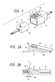
- a locking means as shown in Fig. 1 has been proposed in Japanese Patent Application Laid-open No. 53-49695.
- a cantilevered locking arm 3 having a locking hole 4 thereon is formed between two slits 2, 2 on a cylindrical outer surface 1 of the connector F.
- an engaging protuberance 6 is provided on an outer surface 5 of the connector M.
- a stop 7 is used for protecting the locking arm 3.
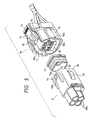
- the letter P indicates the locus described by the inner surface 4a at the leading portion of the hole 4 as the locking arm 3 rotated about the fulcrum 3a and is resiliently restored to its initial state.
- Fig. 3 is a graph showing the relationship between the locking load and the fitting depth (stokes) when the locking arm 3 is locked at the pretuberance 6.
- the locking load f increases with stroke 1 being increased, and reaches a maximum level at a point l1 where the hole 4 rides over the apex 6b of the protuberance 6, after which it decreases sharply and reaches zero. Because of inertia arising from their locked state, both connectors F and M stop when the stroke reaches a value l2.
- an object of the present invention is to eliminate the occurrence of backlash between the pair of connectors, due to the existence of an interval between the locking arm and the engaging protuberance, and to provide a locking device for connectors whose conductive capability is not impaired when used as terminals.
- a locking device for a pair of components comprising: a first component having an outer wall provided with a protuberance having a rear engaging surface; a second component having an outer wall provided with a cantilevered locking arm having a front inner surface engaging with said rear engaging surface of said protuberance; and a backlash preventing means for preventing any backlash from generating between said first and second components in engagement, said backlash preventing means being provided on said rear engaging surface and including a substantially arcuate face which at least partially conforms with a rotational locus formed by said front inner surface of said locking arm when said locking arm pivotally moves.
- the locking arm and the engaging protuberance may lock together so that the inner surface of the locking hole (or depression) is always in contact with or in close proximity to the arcuate surface of the anti-backlash section.
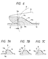
- Fig. 5 shows a male connector M and a female connector F.
- a locking arm 12 is provided on the outer wall 11 of a main body 10 of the male connector M.
- the locking arm 12 has a locking hole 13 at its front end portion, and an operating knob 14 at is rear end portion. Both intermediate legs of the iocking arm 12 are connected to the outer wall 11 through a base 15.
- the locking arm 12 is resiliently rotatable upward or downward about the base 15 which serves as a fulcrum.
- the female connector F has a hood 18 for receiving the main 5 body 10 of the male connector M.
- An engaging protuberance 19 protrudes from the outer wall of the hood 18.
- the front porion of the engaging protuberance 19 has a gentle slant surface 19a, and an anti-backlash section 19b is integrally formed on its rear surface.
- This anti-backlash section 19b is shaped to have an arcuate surface Q′ that corresponds to the locus Q formed by the inner surface 13a at the front part of the locking hole 13 when the locking arm 12 is rotated and displaced in vertical direction about the base 15.
- the male connector M and female connector F are further made to be waterproof.
- the front half portion of the locking arm 12 and the main body 10 are encased together in a waterproof hood 16 which also serves as a receptacle for the hood 18.
- a guide wall 16a and a guide groove 16b are formed on the waterproof hood 16 so as to mate with flanges 20 and 21 to prevent a reverse connector engagement, respectively.
- the connectors F and M are connected together through a gasket 17.
- a terminal chamber 10a of the male connector M and a terminal chamber 18a of the female connector F house the female terminal and male terminal, respectively. Each of the terminals is connected to a wire W, which is not shown in the illustration.
- connection between the male connector M and female connector F is effected in the same manner as shown in Fig. 2A.
- the front end portion of the locking arm 12 gradually moves along the slant surface 19a on the front part of the engaging protuberance 19, the arm 12 is bent upward, while rotating about the base 15.
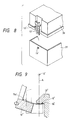
- Figs. 7A to 7C show respective variations of the anti-backlash section 19b of the engaging protuberance 19.
- Fig. 7A shows an anti-backlash section 19b formed with a notch 19d on the lower half portion of the anti-backlash section
- Fig. 7B shows the same anti-backlash section 19b with a notch 19d, formed on the upper half portion.
- Fig. 7C shows the anti-backlash section 19b provided at a position a little distance away from the rear surface of the engaging protuberance 19.
- the arcuate surface Q′ of the anti-backlash section 19b is formed to match the aforementioned locus Q, the same locking effect exhibited by the example shown in Fig. 2 is realized.
- the interval between the locking hole or depression of the locking arm and the engaging protuberance is eliminated. Consequently, the problem of backlash when connecting and locking the pair of connectors is solved. In turn, the problems of wear of the terminals, impairment of the conductive capability, and generation of unwanted noise are also solved. Further, in waterproof connectors wherein a waterproofing gasket is placed between the pair of connectors, the impairment of the water-resistant property due to vibration can also be prevented.
- the similar locking device as described in conjunction with Figs. 5 to 7B may be applied to a box 31 with cover 30.
- the locking device similarly includes a locking arm 12′ having a locking hole 13′ and an associated protuberance 19′ to be engaged with the locking hole 13′.
- the engaging curved surface of the protuberance 13 is arcuate. It is however apparent that a substantially arcuate surface may be used.
- Fig. 9 shows this example in which a locking arm 12 ⁇ has an engaging surface 13a′ may be engaged at point Q ⁇ with the protuberance 13 ⁇ . As shown in Fig. 9, the engaging surface Q ⁇ of the protuberance is not exactly arcuate but substantially arcuate.
Landscapes
- Details Of Connecting Devices For Male And Female Coupling (AREA)
Applications Claiming Priority (2)
| Application Number | Priority Date | Filing Date | Title |
|---|---|---|---|
| JP113462/89U | 1989-09-29 | ||
| JP11346289 | 1989-09-29 |
Publications (2)
| Publication Number | Publication Date |
|---|---|
| EP0420255A1 true EP0420255A1 (fr) | 1991-04-03 |
| EP0420255B1 EP0420255B1 (fr) | 1996-05-01 |
Family
ID=14612853
Family Applications (1)
| Application Number | Title | Priority Date | Filing Date |
|---|---|---|---|
| EP19900118593 Expired - Lifetime EP0420255B1 (fr) | 1989-09-29 | 1990-09-27 | Dispositif de verrouillage pour connecteurs |
Country Status (2)
| Country | Link |
|---|---|
| EP (1) | EP0420255B1 (fr) |
| DE (1) | DE69026782T2 (fr) |
Cited By (6)
| Publication number | Priority date | Publication date | Assignee | Title |
|---|---|---|---|---|
| EP0643446A1 (fr) * | 1993-09-10 | 1995-03-15 | CONNECTEURS CINCH, Société Anonyme dite : | Perfectionnements aux boîtiers de connecteurs électriques |
| US5588865A (en) * | 1993-08-20 | 1996-12-31 | Yazaki Corporation | Connector fastening mechanism |
| EP0740368A3 (fr) * | 1995-04-26 | 1998-01-14 | Sumitomo Wiring Systems, Ltd. | Dispositif de rétention tubulaire |
| US10559948B2 (en) | 2018-05-08 | 2020-02-11 | Yazaki Corporation | Casing, electrical connection box, and wire harness |
| CN111262066A (zh) * | 2017-06-23 | 2020-06-09 | 上海莫仕连接器有限公司 | 电源连接器 |
| US10752187B2 (en) | 2018-05-08 | 2020-08-25 | Yazaki Corporation | Casing, electrical connection box, and wire harness |
Families Citing this family (1)
| Publication number | Priority date | Publication date | Assignee | Title |
|---|---|---|---|---|
| DE102022105676A1 (de) | 2022-03-10 | 2023-09-14 | WAGO Verwaltungsgesellschaft mit beschränkter Haftung | Gehäuse eines elektrischen Steckverbinders und elektrischer Steckverbinder |
Citations (2)
| Publication number | Priority date | Publication date | Assignee | Title |
|---|---|---|---|---|
| US3933406A (en) * | 1974-01-04 | 1976-01-20 | Ford Motor Company | Electrical connector block assembly having overcenter locking |
| EP0028120A1 (fr) * | 1979-10-22 | 1981-05-06 | Ford Motor Company Limited | Dispositif de déverrouillage pour connecteur |
-
1990
- 1990-09-27 EP EP19900118593 patent/EP0420255B1/fr not_active Expired - Lifetime
- 1990-09-27 DE DE1990626782 patent/DE69026782T2/de not_active Expired - Lifetime
Patent Citations (2)
| Publication number | Priority date | Publication date | Assignee | Title |
|---|---|---|---|---|
| US3933406A (en) * | 1974-01-04 | 1976-01-20 | Ford Motor Company | Electrical connector block assembly having overcenter locking |
| EP0028120A1 (fr) * | 1979-10-22 | 1981-05-06 | Ford Motor Company Limited | Dispositif de déverrouillage pour connecteur |
Cited By (9)
| Publication number | Priority date | Publication date | Assignee | Title |
|---|---|---|---|---|
| US5588865A (en) * | 1993-08-20 | 1996-12-31 | Yazaki Corporation | Connector fastening mechanism |
| EP0643446A1 (fr) * | 1993-09-10 | 1995-03-15 | CONNECTEURS CINCH, Société Anonyme dite : | Perfectionnements aux boîtiers de connecteurs électriques |
| EP0740368A3 (fr) * | 1995-04-26 | 1998-01-14 | Sumitomo Wiring Systems, Ltd. | Dispositif de rétention tubulaire |
| US5782658A (en) * | 1995-04-26 | 1998-07-21 | Sumitomo Wiring Systems, Ltd. | Tubular supporting structure |
| CN111262066A (zh) * | 2017-06-23 | 2020-06-09 | 上海莫仕连接器有限公司 | 电源连接器 |
| US10965058B2 (en) | 2017-06-23 | 2021-03-30 | Molex, Llc | Power connector |
| CN111262066B (zh) * | 2017-06-23 | 2021-10-01 | 上海莫仕连接器有限公司 | 电源连接器 |
| US10559948B2 (en) | 2018-05-08 | 2020-02-11 | Yazaki Corporation | Casing, electrical connection box, and wire harness |
| US10752187B2 (en) | 2018-05-08 | 2020-08-25 | Yazaki Corporation | Casing, electrical connection box, and wire harness |
Also Published As
| Publication number | Publication date |
|---|---|
| EP0420255B1 (fr) | 1996-05-01 |
| DE69026782T2 (de) | 1996-09-05 |
| DE69026782D1 (de) | 1996-06-05 |
Similar Documents
| Publication | Publication Date | Title |
|---|---|---|
| US5336101A (en) | Connector assembly | |
| JP3250787B2 (ja) | 電気コネクタのロック装置 | |
| JP2757139B2 (ja) | シールド型コネクタ | |
| US5759058A (en) | Connector position assurance component | |
| US5203715A (en) | Connector | |
| US5711684A (en) | Connector housing locking mechanism | |
| JP3415008B2 (ja) | コネクタ | |
| EP1176676B1 (fr) | Structure fixation pour connecteur | |
| EP0805523A2 (fr) | Système de verrouillage pour connecteurs électriques | |
| US20010023154A1 (en) | Connector fitting structure | |
| EP0788193A2 (fr) | Connecteur électrique | |
| MY113086A (en) | Locking system for an electrical connector assembly | |
| GB2248349A (en) | Means for disconnecting electrical connectors | |
| US6527578B2 (en) | Connector fitting structure | |
| EP0420255A1 (fr) | Dispositif de verrouillage pour connecteurs | |
| US6341973B1 (en) | Half-fitting prevention connector for detecting and preventing half-fitted condition | |
| EP0646993B1 (fr) | Assemblage de connecteur électrique avec mécanisme de verrouillage à levier à came | |
| US6475015B1 (en) | Half-fitting prevention connector | |
| US6416345B1 (en) | Connector lock mechanism with elastic arm portion | |
| JP3314100B2 (ja) | コネクタのロック機構 | |
| JP2576785Y2 (ja) | 防水コネクタの嵌合構造 | |
| US5613878A (en) | Reverse insertion preventing connector | |
| US6478632B2 (en) | Shake preventing construction for a terminal fitting and a connector | |
| JPH09306592A (ja) | コネクタの嵌合構造 | |
| JPH0751742Y2 (ja) | 電気コネクタのロック装置 |
Legal Events
| Date | Code | Title | Description |
|---|---|---|---|
| PUAI | Public reference made under article 153(3) epc to a published international application that has entered the european phase |
Free format text: ORIGINAL CODE: 0009012 |
|
| AK | Designated contracting states |
Kind code of ref document: A1 Designated state(s): DE FR GB |
|
| 17P | Request for examination filed |
Effective date: 19911002 |
|
| 17Q | First examination report despatched |
Effective date: 19931213 |
|
| GRAH | Despatch of communication of intention to grant a patent |
Free format text: ORIGINAL CODE: EPIDOS IGRA |
|
| GRAA | (expected) grant |
Free format text: ORIGINAL CODE: 0009210 |
|
| AK | Designated contracting states |
Kind code of ref document: B1 Designated state(s): DE FR GB |
|
| REF | Corresponds to: |
Ref document number: 69026782 Country of ref document: DE Date of ref document: 19960605 |
|
| ET | Fr: translation filed | ||
| PLBE | No opposition filed within time limit |
Free format text: ORIGINAL CODE: 0009261 |
|
| STAA | Information on the status of an ep patent application or granted ep patent |
Free format text: STATUS: NO OPPOSITION FILED WITHIN TIME LIMIT |
|
| 26N | No opposition filed | ||
| REG | Reference to a national code |
Ref country code: GB Ref legal event code: IF02 |
|
| PGFP | Annual fee paid to national office [announced via postgrant information from national office to epo] |
Ref country code: GB Payment date: 20090923 Year of fee payment: 20 |
|
| PGFP | Annual fee paid to national office [announced via postgrant information from national office to epo] |
Ref country code: DE Payment date: 20090923 Year of fee payment: 20 |
|
| PGFP | Annual fee paid to national office [announced via postgrant information from national office to epo] |
Ref country code: FR Payment date: 20091012 Year of fee payment: 20 |
|
| REG | Reference to a national code |
Ref country code: GB Ref legal event code: PE20 Expiry date: 20100926 |
|
| PG25 | Lapsed in a contracting state [announced via postgrant information from national office to epo] |
Ref country code: GB Free format text: LAPSE BECAUSE OF EXPIRATION OF PROTECTION Effective date: 20100926 |
|
| PG25 | Lapsed in a contracting state [announced via postgrant information from national office to epo] |
Ref country code: DE Free format text: LAPSE BECAUSE OF EXPIRATION OF PROTECTION Effective date: 20100927 |