EP0420363A1 - Système pour le recouvrement de voies ferrées - Google Patents
Système pour le recouvrement de voies ferrées Download PDFInfo
- Publication number
- EP0420363A1 EP0420363A1 EP90250228A EP90250228A EP0420363A1 EP 0420363 A1 EP0420363 A1 EP 0420363A1 EP 90250228 A EP90250228 A EP 90250228A EP 90250228 A EP90250228 A EP 90250228A EP 0420363 A1 EP0420363 A1 EP 0420363A1
- Authority
- EP
- European Patent Office
- Prior art keywords
- device system
- track
- tubs
- trough
- rails
- Prior art date
- Legal status (The legal status is an assumption and is not a legal conclusion. Google has not performed a legal analysis and makes no representation as to the accuracy of the status listed.)
- Granted
Links
- 239000004033 plastic Substances 0.000 claims abstract description 35
- 229920003023 plastic Polymers 0.000 claims abstract description 35
- 239000000758 substrate Substances 0.000 claims abstract description 7
- XLYOFNOQVPJJNP-UHFFFAOYSA-N water Substances O XLYOFNOQVPJJNP-UHFFFAOYSA-N 0.000 claims description 19
- 239000002023 wood Substances 0.000 claims description 6
- 238000003973 irrigation Methods 0.000 claims description 5
- 230000002262 irrigation Effects 0.000 claims description 5
- 239000002184 metal Substances 0.000 claims description 4
- 229910052751 metal Inorganic materials 0.000 claims description 4
- 238000005260 corrosion Methods 0.000 claims description 3
- 230000007797 corrosion Effects 0.000 claims description 3
- 230000000284 resting effect Effects 0.000 claims description 3
- 239000003086 colorant Substances 0.000 claims 1
- 244000025254 Cannabis sativa Species 0.000 abstract description 9
- 230000012010 growth Effects 0.000 abstract description 3
- 235000008216 herbs Nutrition 0.000 abstract 1
- 230000003014 reinforcing effect Effects 0.000 abstract 1
- 239000000463 material Substances 0.000 description 19
- 241001669679 Eleotris Species 0.000 description 17
- 101150114468 TUB1 gene Proteins 0.000 description 9
- 238000013461 design Methods 0.000 description 8
- 229910000831 Steel Inorganic materials 0.000 description 6
- 238000010276 construction Methods 0.000 description 6
- -1 polyethylene Polymers 0.000 description 6
- 239000010959 steel Substances 0.000 description 6
- 239000004567 concrete Substances 0.000 description 5
- 241000196324 Embryophyta Species 0.000 description 4
- 239000004698 Polyethylene Substances 0.000 description 4
- 239000011324 bead Substances 0.000 description 4
- 238000005452 bending Methods 0.000 description 4
- 229920001971 elastomer Polymers 0.000 description 4
- 239000006260 foam Substances 0.000 description 4
- 230000006870 function Effects 0.000 description 4
- 229920000573 polyethylene Polymers 0.000 description 4
- 239000010426 asphalt Substances 0.000 description 3
- 230000004888 barrier function Effects 0.000 description 3
- 239000004927 clay Substances 0.000 description 3
- 230000000295 complement effect Effects 0.000 description 3
- 239000000806 elastomer Substances 0.000 description 3
- 238000009434 installation Methods 0.000 description 3
- 238000004519 manufacturing process Methods 0.000 description 3
- 239000004576 sand Substances 0.000 description 3
- 239000002689 soil Substances 0.000 description 3
- 239000004575 stone Substances 0.000 description 3
- 238000004026 adhesive bonding Methods 0.000 description 2
- 230000008901 benefit Effects 0.000 description 2
- 238000004040 coloring Methods 0.000 description 2
- 239000002131 composite material Substances 0.000 description 2
- 239000000428 dust Substances 0.000 description 2
- 238000005516 engineering process Methods 0.000 description 2
- 230000007613 environmental effect Effects 0.000 description 2
- 239000003063 flame retardant Substances 0.000 description 2
- 239000003365 glass fiber Substances 0.000 description 2
- 239000002440 industrial waste Substances 0.000 description 2
- 238000003780 insertion Methods 0.000 description 2
- 230000037431 insertion Effects 0.000 description 2
- 238000009413 insulation Methods 0.000 description 2
- 238000000034 method Methods 0.000 description 2
- 238000004064 recycling Methods 0.000 description 2
- 230000001105 regulatory effect Effects 0.000 description 2
- 239000007787 solid Substances 0.000 description 2
- 239000007921 spray Substances 0.000 description 2
- 238000003860 storage Methods 0.000 description 2
- RNFJDJUURJAICM-UHFFFAOYSA-N 2,2,4,4,6,6-hexaphenoxy-1,3,5-triaza-2$l^{5},4$l^{5},6$l^{5}-triphosphacyclohexa-1,3,5-triene Chemical compound N=1P(OC=2C=CC=CC=2)(OC=2C=CC=CC=2)=NP(OC=2C=CC=CC=2)(OC=2C=CC=CC=2)=NP=1(OC=1C=CC=CC=1)OC1=CC=CC=C1 RNFJDJUURJAICM-UHFFFAOYSA-N 0.000 description 1
- 235000007575 Calluna vulgaris Nutrition 0.000 description 1
- 206010016275 Fear Diseases 0.000 description 1
- 229910001335 Galvanized steel Inorganic materials 0.000 description 1
- 239000004594 Masterbatch (MB) Substances 0.000 description 1
- 239000004952 Polyamide Substances 0.000 description 1
- 239000004743 Polypropylene Substances 0.000 description 1
- 229920006328 Styrofoam Polymers 0.000 description 1
- HCHKCACWOHOZIP-UHFFFAOYSA-N Zinc Chemical compound [Zn] HCHKCACWOHOZIP-UHFFFAOYSA-N 0.000 description 1
- 238000010521 absorption reaction Methods 0.000 description 1
- 239000000654 additive Substances 0.000 description 1
- 230000000996 additive effect Effects 0.000 description 1
- 230000033228 biological regulation Effects 0.000 description 1
- 239000004568 cement Substances 0.000 description 1
- 239000003795 chemical substances by application Substances 0.000 description 1
- 238000005352 clarification Methods 0.000 description 1
- 230000003749 cleanliness Effects 0.000 description 1
- 239000011248 coating agent Substances 0.000 description 1
- 238000000576 coating method Methods 0.000 description 1
- 230000002950 deficient Effects 0.000 description 1
- 230000001419 dependent effect Effects 0.000 description 1
- 238000011161 development Methods 0.000 description 1
- 230000018109 developmental process Effects 0.000 description 1
- 239000010791 domestic waste Substances 0.000 description 1
- 238000007688 edging Methods 0.000 description 1
- 238000004870 electrical engineering Methods 0.000 description 1
- 238000010616 electrical installation Methods 0.000 description 1
- 239000003344 environmental pollutant Substances 0.000 description 1
- 238000002474 experimental method Methods 0.000 description 1
- 239000000945 filler Substances 0.000 description 1
- 238000009415 formwork Methods 0.000 description 1
- 239000008397 galvanized steel Substances 0.000 description 1
- 230000006872 improvement Effects 0.000 description 1
- 230000006698 induction Effects 0.000 description 1
- 239000007788 liquid Substances 0.000 description 1
- 230000007774 longterm Effects 0.000 description 1
- 239000000696 magnetic material Substances 0.000 description 1
- 238000012423 maintenance Methods 0.000 description 1
- 230000007246 mechanism Effects 0.000 description 1
- 239000000203 mixture Substances 0.000 description 1
- 235000015097 nutrients Nutrition 0.000 description 1
- 230000003287 optical effect Effects 0.000 description 1
- 238000010422 painting Methods 0.000 description 1
- 239000002373 plant growth inhibitor Substances 0.000 description 1
- 239000002985 plastic film Substances 0.000 description 1
- 231100000719 pollutant Toxicity 0.000 description 1
- 229920002647 polyamide Polymers 0.000 description 1
- 229920000098 polyolefin Polymers 0.000 description 1
- 229920001155 polypropylene Polymers 0.000 description 1
- 230000008092 positive effect Effects 0.000 description 1
- 230000008569 process Effects 0.000 description 1
- 238000012545 processing Methods 0.000 description 1
- 230000005855 radiation Effects 0.000 description 1
- 239000002994 raw material Substances 0.000 description 1
- 230000009467 reduction Effects 0.000 description 1
- 230000008439 repair process Effects 0.000 description 1
- 230000002441 reversible effect Effects 0.000 description 1
- 239000005060 rubber Substances 0.000 description 1
- 238000007789 sealing Methods 0.000 description 1
- 239000004071 soot Substances 0.000 description 1
- 125000006850 spacer group Chemical group 0.000 description 1
- 230000006641 stabilisation Effects 0.000 description 1
- 238000011105 stabilization Methods 0.000 description 1
- 239000003351 stiffener Substances 0.000 description 1
- 239000008261 styrofoam Substances 0.000 description 1
- 229920001169 thermoplastic Polymers 0.000 description 1
- 239000012815 thermoplastic material Substances 0.000 description 1
- 239000004416 thermosoftening plastic Substances 0.000 description 1
- 230000008719 thickening Effects 0.000 description 1
- 230000007704 transition Effects 0.000 description 1
- 239000002699 waste material Substances 0.000 description 1
- 238000009333 weeding Methods 0.000 description 1
- 238000003466 welding Methods 0.000 description 1
- 239000011701 zinc Substances 0.000 description 1
- 229910052725 zinc Inorganic materials 0.000 description 1
Images

Classifications
-
- E—FIXED CONSTRUCTIONS
- E01—CONSTRUCTION OF ROADS, RAILWAYS, OR BRIDGES
- E01B—PERMANENT WAY; PERMANENT-WAY TOOLS; MACHINES FOR MAKING RAILWAYS OF ALL KINDS
- E01B19/00—Protection of permanent way against development of dust or against the effect of wind, sun, frost, or corrosion; Means to reduce development of noise
- E01B19/006—Means for protecting the underground against spillage
-
- E—FIXED CONSTRUCTIONS
- E01—CONSTRUCTION OF ROADS, RAILWAYS, OR BRIDGES
- E01B—PERMANENT WAY; PERMANENT-WAY TOOLS; MACHINES FOR MAKING RAILWAYS OF ALL KINDS
- E01B19/00—Protection of permanent way against development of dust or against the effect of wind, sun, frost, or corrosion; Means to reduce development of noise
- E01B19/003—Means for reducing the development or propagation of noise
-
- E—FIXED CONSTRUCTIONS
- E01—CONSTRUCTION OF ROADS, RAILWAYS, OR BRIDGES
- E01B—PERMANENT WAY; PERMANENT-WAY TOOLS; MACHINES FOR MAKING RAILWAYS OF ALL KINDS
- E01B2/00—General structure of permanent way
-
- E—FIXED CONSTRUCTIONS
- E01—CONSTRUCTION OF ROADS, RAILWAYS, OR BRIDGES
- E01C—CONSTRUCTION OF, OR SURFACES FOR, ROADS, SPORTS GROUNDS, OR THE LIKE; MACHINES OR AUXILIARY TOOLS FOR CONSTRUCTION OR REPAIR
- E01C9/00—Special pavings; Pavings for special parts of roads or airfields
- E01C9/004—Pavings specially adapted for allowing vegetation
-
- E—FIXED CONSTRUCTIONS
- E01—CONSTRUCTION OF ROADS, RAILWAYS, OR BRIDGES
- E01C—CONSTRUCTION OF, OR SURFACES FOR, ROADS, SPORTS GROUNDS, OR THE LIKE; MACHINES OR AUXILIARY TOOLS FOR CONSTRUCTION OR REPAIR
- E01C9/00—Special pavings; Pavings for special parts of roads or airfields
- E01C9/04—Pavings for railroad level-crossings
-
- E—FIXED CONSTRUCTIONS
- E01—CONSTRUCTION OF ROADS, RAILWAYS, OR BRIDGES
- E01F—ADDITIONAL WORK, SUCH AS EQUIPPING ROADS OR THE CONSTRUCTION OF PLATFORMS, HELICOPTER LANDING STAGES, SIGNS, SNOW FENCES, OR THE LIKE
- E01F8/00—Arrangements for absorbing or reflecting air-transmitted noise from road or railway traffic
-
- E—FIXED CONSTRUCTIONS
- E01—CONSTRUCTION OF ROADS, RAILWAYS, OR BRIDGES
- E01B—PERMANENT WAY; PERMANENT-WAY TOOLS; MACHINES FOR MAKING RAILWAYS OF ALL KINDS
- E01B1/00—Ballastway; Other means for supporting the sleepers or the track; Drainage of the ballastway
- E01B1/001—Track with ballast
-
- E—FIXED CONSTRUCTIONS
- E01—CONSTRUCTION OF ROADS, RAILWAYS, OR BRIDGES
- E01B—PERMANENT WAY; PERMANENT-WAY TOOLS; MACHINES FOR MAKING RAILWAYS OF ALL KINDS
- E01B2204/00—Characteristics of the track and its foundations
- E01B2204/11—Embedded tracks, using prefab elements or injecting or pouring a curable material
-
- E—FIXED CONSTRUCTIONS
- E01—CONSTRUCTION OF ROADS, RAILWAYS, OR BRIDGES
- E01B—PERMANENT WAY; PERMANENT-WAY TOOLS; MACHINES FOR MAKING RAILWAYS OF ALL KINDS
- E01B2204/00—Characteristics of the track and its foundations
- E01B2204/14—Vegetation on or around railway-tracks
Definitions
- the invention relates to a device system and a greening system for track systems according to the preambles of claims 1 and 24 and the use of a device system as a track crossing.
- the traditional route for the railroad is the ballast track. Solid roadways made of concrete or asphalt are the exception.
- the increase in traffic density in the metropolitan areas necessitates an increased expansion of the underground, suburban and urban railways, and shorter cycle times for the construction and operation of the railways make sense. This increases the environmental impact and places greater demands on the track body in order to reduce it.
- bridge-forming rail transition plates are known, for example the Semperit-Bodan system, in which steel-concrete plates are arranged between the rails on rubber bearings which are supported on the rail foot.
- the invention makes use of known techniques. From DE-OS 3511552 it is known to position oil drip pans between the rails in shunting areas and train stations and to discharge the liquid pollutants.
- the invention can be used with all sleeper types and sleeper distances and the control of the superstructure materials as well as the re-stuffing of the track systems is still possible.
- a tub for the generic covering systems which is designed to be rigid and can be easily positioned between and next to the rails on supports.
- the tubs have a number of positive properties.
- tubs which are made of, for example, galvanized, plastic-coated or bituminized steel sheet or plastic, have a u-shaped cross section and are a few meters long, soil or a special substrate such as expanded clay, sand or the like can be contained as a base and nutrient collector. If necessary, both a layer of water-storing, drainable material and an earth layer for plantings can be introduced into the tub.
- the tubs should be designed as containers that are open on one side. However, a side wall can be dispensed with in special cases if the adjacent neighboring container has a common wall for both containers.
- tubs For standard tracks, between the rails and on the sleeper heads, i. H. can be arranged on the outside of the tracks, tubs. For economic reasons, the tubs should be as identical as possible regardless of their installation position.
- the support strips can also be locked in support profiles designed as clamping profiles.
- Such support profiles and support strips can also be placed, screwed, glued or welded onto the sleeper heads, depending on whether the sleepers are made of wood, concrete, steel or plastic.
- a support profile is either attached to the sleeper end or e.g. embedded in the ground in the form of an angled lawn edging stone. This angle, or profile of other cross-section, serves at the same time as a support for the tub and as a closure or curb for the area adjacent to the track - lawn, flower bed, street or the like.
- the support strip should be designed as an elastic, rot-proof plastic strip or consist of wood. It compensates for height differences and allows long-term stable and reversible load-dependent bending or torsion of the tub, for example when a vehicle rolls over the tub. In addition, vibrations from the track system are not transferred to the planting tubs and the tubs are electrically against e.g. B. isolated a steel sleeper system. Plastic is well suited for these purposes.
- the insertion and removal of the tubs from the track can easily be done by two people with plastic tubs up to a few meters in length. However, if there is water in the tubs or if it becomes too heavy due to its great length, depth, weight or earth weight, or if longer track sections need to be cleared, the tubs can be moved with lifting gear.
- devices, eyelets or brackets are attached to the tubs, on which load means such as crane hooks, ropes or chains can be attached.
- the troughs are designed as boxes that are open at the top, rectangular or square in plan view, with stiffening ribs. These boxes can be arranged in a cassette-like manner between the rails and on the side sleeper heads in rows.
- the boxes or cassettes have e.g. an edge length of approx. 50 cm and a height of approx. 12 cm and are reinforced by ribs which have, for example, approximately half the height of the cassette walls or more and thus form 4, 6, 8, 9, 12 or more fields in the cassette .
- Cassettes designed in this way only weigh about 5 to 10 kg, depending on the plastic used.
- a support bar in the form of a lying T is attached to the center of a bathtub side or cassette side.
- the total width of, for example, two adjacent boxes including the support bar should be less than the free distance between the rail heads and leave the rail attachment free for checks.
- the boxes each have two support strips as supports on the sleepers.
- a central support strip serves as a support for two adjacent boxes, while support strips near the rails support the support strips of the boxes in a form-fitting manner.
- the corners of the boxes have recesses, which are designed, for example, so that four corners form a common free breakthrough through the cover plane of the track formed by the cassettes.
- the opening for example with a cloverleaf-like cross section, can be filled out with a lock.
- This lock which can only be removed with a special key, prevents the cassettes from being offset from one another or the unauthorized removal of cassettes from the track.
- the lock consists of four parallel cylinders connected to each other, which in complementary recesses of the boxes intervention. If necessary, the locking lock is conical to pull the boxes against each other in the installed position as soon as the lock is inserted.
- the setbacks have two other uses. Conical bolts or hooks of a load device can be attached there to move the boxes. Spacers can also be inserted into the recesses, so that the boxes can be stacked close to one another and / or at a predetermined distance above one another. This is a great advantage for transport to or storage at the construction site, to save space or to protect planting in the boxes.
- the troughs of the system leave the strips of the track adjacent to the rails free in order to make the rail fastening accessible or to allow space for the wheel flanges.
- Cover profiles can be used according to the invention in the rail-parallel free spaces or track grooves. To prevent unauthorized removal, they can be clamped between the rail web and the support rail of the trays. It is also possible to provide the cover profiles with recesses similar to the tubs and also to use the locking mechanism described above.
- the design of the cover over the rail fastening is chosen according to the broadest base design. This measure allows the rail fastening material to be checked, maintained and renewed, a rail to be replaced and individual lowering points to be tamped with sleepers using hand tampers without removing the cassettes. Wide covers next to the rails prevent the grass from laying on the rail heads and causing the rail vehicles to slide when braking when the grass in cassettes used as a greening system is excessively high.
- the device system according to the invention is supplemented on the sides of the track systems by profile elements which can be positively locked with the tubs or inserted into the recesses of the tubs.
- profile elements can optionally have multiple functions or be designed according to the functions. They can serve as a noise barrier for emissions from rail operations. For this purpose, they are designed as a stable frame in which a formwork filled with sand or plastics is inserted. Likewise, other known sound-absorbing perforated or laminated panels with or without filling can of course be mounted in the frame. Adjacent profile elements can be connected to each other by the same clamping profile as is used as a support profile to increase stability. Furthermore, the profile elements with appropriate height dimensions can be used as a fence against unauthorized crossing of the tracks.
- the profile elements can be used as a holder for, for example, photovoltaic solar collectors, in order, for example, to supply the necessary current with signal systems for railway operation or warning signals at roadway crossings. This eliminates the need for longer power supplies.
- the profile elements can be easily replaced, so that, for example, an exchange of defective elements is facilitated.
- the profile elements are also secured against theft by a lock.
- a preferred embodiment of the cassettes is used to green track systems.
- a lawn track can be created by suitable planting over an existing ballast bed or an easy-care, sound-absorbing, walkable and drivable surface can be produced.
- this design eliminates the need to use spray agents to prevent the ballast bed from weeding, since the cover protects it from light and prevents growth in the ballast bed.
- the use of greening systems in troughs or tubs is no problem, as the state of the art has shown, for example, when greening on flat roofs.
- the greening system fulfills all the requirements that have to be placed on such systems, also known as lawn tracks.
- the good sound reduction through lawn tracks is largely known and proven. Designs other than those described here have already been used in Basel, Zurich, Amsterdam, Stuttgart, Hanover.
- the greening system according to the invention when used as a lawn track, - gravel tracks are integrated into lawns, - separate tracks are planted in streets, - green tracks in underground stations, or, when used as a soundproofing and cleanliness track, - Gravel track areas covered in platform systems, - Tracks in subway stations are covered to keep them clean.
- the tub system according to the invention can also be used in the asphalt superstructure. Here there is no need for ballasting the tracks for the purpose of sound insulation or to prevent softening of the surface due to solar radiation.
- the tub is provided with a perforated floor and the leachate from rainfall or irrigation can run unimpeded into the track bed. With intensive greening, however, targeted water drainage is necessary.
- the tubs are provided with longitudinal ribs or beads, which divide the tubs into several longitudinal chambers. These chambers regulate the water level. The maximum water level can be specified by the height of the beads or ribs and / or transverse bores in the ribs and the lateral water walls.
- Track systems often have gradients in the longitudinal direction (e.g. mountain routes) and transverse direction (e.g. curve elevation).
- the longitudinal ribs With the longitudinal ribs, the water level in the tub can be determined in the event of a cross slope. If the fin height is always the same, terrain adjustments are possible through holes in the ribs and any overflow tubes to be used.
- the tubs In the case of longitudinal slopes, the tubs must be provided with transverse ribs in the event of intensive greening in order to guarantee a predeterminable maximum / minimum water level. With a slight slope, the tubs can be chosen shorter, so that the trough length, i.e. H. the front and rear transverse wall of the tub determine the level difference. If there is a steep incline or longer tubs, cross ribs must be arranged in the tub.
- Corresponding welded steel walls can be obtained from sheet metal trays or corrugated. If plastic tubs are used, transverse walls must be glued in, or factory-made tubs of this type are sprayed, blown, cast, thermally formed or deep-drawn.
- tubs for planting serve as storage for rainwater for a long time.
- the rib arrangement and the sheet thickness or plastic thickness used have a direct influence on the torsional and bending strength, in particular also on the longitudinal stability of the tubs. Therefore, even with extensive greening, it can be useful to provide the tubs with stiffeners in addition to bottom holes or overflow holes for the water.
- the bottom holes are factory-made as predetermined breaking points and, depending on the requirements and depending on the application, can be pierced at the later place of use.
- the tubs should have a corresponding strength and bending stiffness, which can be adjusted by a targeted selection of the type of material, material thickness and ribbing.
- Plastic trays or lightweight concrete trays made of non-magnetic materials, such as wood, zinc or cement-bound materials, could be used if the railway operation fears retroactive resistances or induction from DC and signal current systems when using steel trays.
- direct current e.g. B. trams
- pitting corrosion could occur on the steel tubs with damaged corrosion protection; plastic tubs should then also be used there.
- the tubs are not to be spaced from the rails from the start, the tubs have recesses for fasteners. Such recesses in the tub floor or in the walls enable an adjustment of the tubs over the rail fastenings.
- each metallic trough should have at least one recess through which an earthing strap can be fed into the track bed or all troughs e.g. be connected on a threshold by a common band.
- the tub height can be selected depending on the substrate filling, water level and planting, but should not protrude above the rail head.
- a larger gap between the trough and the rail must be left for the wheel flange of the railway wheels; on the outside of the rail, this gap can be minimal.
- This arrangement is important in that z. B. in platform areas or on railway tracks with a sealed neighboring surface, always finr sufficient drainage. With greening systems, there is no need for such a drainage effort, since the tubs ensure that the water level is equalized.
- the invention is to be used in the subway area, in particular in underground train stations, it makes sense to form the natural atmosphere on the earth's surface by means of appropriate irrigation systems under the platform edge, which are connected to perforated distributor pipes in the tubs. In addition, special plant lights would then have to be installed. If there is a large amount of dust, the irrigation systems should be designed as leaf spray systems. The greening in the train stations acts as additional sound insulation and as a dust catcher.
- tubs, cassettes or troughs are designed as track crossings in lawns or as sidewalks and cart crossings.
- the open side of the trough is turned towards the ground, so that the bottom of the boxes serves as a running or driving level for pedestrians or non-track-bound vehicles.
- the load-bearing capacity of the individual boxes can be adapted to traffic requirements.
- the position of the boxes can be ensured by the locks described above or additional fastenings.
- the cover profiles fulfill the function of keeping the track grooves clean or, as known from the prior art, of preventing accidents.
- the bottom of the boxes can have a non-slip structure similar to grit or asphalt, which can be ensured by the plastic material used or a corresponding coating of sheet metal trays.
- the bottom of the cassettes can also be covered.
- This cassette arrangement has a particular advantage when used in tunnel sections. Due to the small track width in tunnels, the auxiliary vehicles can only use the track as a track when building a railway line or in the event of a disaster. In principle, ambulances or fire trucks or trucks are not designed as wheeled vehicles for this purpose. If, however, the boxes described are arranged as a route between and next to the rails, or if existing boxes are turned over, a surface that is well accessible for wheeled vehicles is created. Of course, the cassette must be adapted to the intended use and loading purposes with regard to its stability.
- the troughs can be designed in color so that, for example, the trough floor serves as a warning marking for the track systems on passable crossings, e.g. is colored red-white or black-yellow.
- the coloring is done by subsequent painting, but can also be achieved with plastic tubs by adding a masterbatch during production. Planting can also be chosen so that an optical barrier is created by coloring.
- tubs or their floors can also be covered with ready-made lawn or designed with natural materials such as plastic lawn or carpet.
- the system according to the invention can also be used in novel threshold systems with variable threshold spacing, for example Y thresholds, since the support strips enable the cassettes to be used regardless of the distance.
- the short design of the cassettes means that there are no problems even in track curves, since the required curvature offset of a few millimeters per cassette is possible.
- the cover profiles are kept flexible accordingly. In particular, when using plastics for the cover profiles, which may receive firmer molded sections by combining harder plastics with softer foams or inserted or cast metal or wooden inserts in the area of their fastenings, the necessary flexibility is given.
- the cover profile can consist of integrated or composite materials.
- the materials can be sprayed together or permanently bonded to one another by gluing, welding or similar processes get connected.
- the cover profile made of polyethylene is foamed with fillers such as glass fibers, sprayed and sprayed with foam or provided with a highly elastic plastic in the area of the later rail system. This is used for bending the cover profiles when clamping them into the track grooves or free spaces between the cassettes and rails and when adapting to the curve radii of the tracks.
- a high level of structure-borne noise absorption is achieved by using this material and flush contact with the rail.
- the tubs, support profiles, cover profiles and other parts of the device system according to the invention are preferably made from recycled plastic.
- thermoplastic from household waste, industrial waste, old tires, vehicles and residues from electrical engineering and installation technology can be used.
- Semi-crystalline base material made of polyethylene and polypropylene has proven to be particularly suitable. However, other recyclable polyolefins, polyamides or other thermoplastic materials can also be formed directly for the purpose mentioned without using new plastics. For special requirements, such as heavy load crossings in tunnels, a higher quality raw material from original waste or typed industrial waste may have to be used. A soot additive may be required to ensure sufficient UV stabilization of the components.
- the support strips When using the specified materials, the support strips also have the flexibility required for the intended purpose. For price reasons, for example, they can also be made from wood. To adapt to the different threshold shapes or profile heights of the rails or thresholds, the effort for the tool shapes would be too high under certain circumstances when manufacturing from plastic.
- plastic material creates a durable, solid, versatile and economical construction for almost all individual parts of the system. Since the basic material consists of a recycling product, additional environmental protection is practiced. The good material properties allow the plastic to be used in open sections and in tunnels. The use of flame-retardant materials is a prerequisite for use in tunnels. This is guaranteed with the specified materials. If necessary, flame retardants can be added to the plastic during processing to improve flame protection.
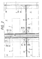
- a trough 1 planted with grass 20 lies between the rails 5, which are secured to the rail foot 6 with the fastenings 34, 35 on the wooden sleeper 4.
- Fig. 1 only one rail 5 and one half of the tub 1 is shown.
- a lawn area 3 is delimited towards the track by an angular curb 30 embedded in sand 9.
- a tub 2 covered with grass 20 is inserted; the turf is at the level of the head of the rail 5, so that the track can only be recognized by the interruption of the grass surface by the rail heads.
- the tub 1 consists of galvanized steel sheet with a thickness of 2 mm. It has 3 cm deep longitudinal ribs 11 in the bottom 10; their total depth between the floor 10 and the upper edge of the tub rim 15 is approximately 13 cm.
- the transverse ribs 12 and the transverse wall 40 (FIG. 2) are welded in.
- the tub edge 15 ends at a distance 21 for the wheel flange of the railroad wheels in front of the rail 5.
- a recess 13 in the tub 1 enables the rail fastening 34 to protrude above it.
- the tub 1 lies on the bottom 10 on an elastomer cushion 31 of 6 cm wide and 30 cm long.
- the pillow 31 has a barb-shaped nose 32 which projects into a slotted profile 33 and is thus fixed.
- the profile 33 is screwed onto the threshold 4 located in the ballast 8.
- a web 42 on the bottom 10 of the tub 1 prevents the gap 21 from becoming smaller by moving the tub 1.
- the tub 2 alternatively shows a smooth floor 25 with which this tub rests on the sleeper head in the same way as tub 1.
- the second support for the tub 1 forms one Elastomer cushion 29 on the curb 30.
- a recess 24 for the rail fastening 35 in the floor 25 allows the tub 2 with the tub rim 23 to be placed on the rail 5 except for a gap 22 necessary for inserting the tub 2.
- Both troughs 1, 2 are filled with an expanded clay layer 16 of 5 cm thick, on which a filter mat 18 or 26 lies, over which a 7 cm thick layer 17 of permanent soil is arranged, into which grass 20 has been sown.
- expanded clay instead of expanded clay, other water-storing layers, e.g. made of styrofoam or foams.
- the overflow holes 14 and 27, 28 in the tub walls serve to regulate the water level.
- the transverse ribs 12 guarantee a minimum water level in the event of a longitudinal gradient and increase the tub stiffness.
- Fig. 2 shows how two trays 1 and 2 are arranged one behind the other in the track.
- the transverse walls 40 and the longitudinal walls 15 of the tub 1 or the transverse walls 41 and the longitudinal walls 23 of the tub 2 are provided with gusset plates 36 and 38, to which eyelets 37 and 39 are fastened, around the tub with rope hooks to be able to heave the track.
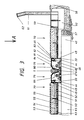
- Fig. 3 shows a section through a grass track half with a device system of a slightly different design than shown in Fig. 1.
- identical components of the system described below have the same numbering in all figures in order to clarify their identical design.
- troughs 70 made of recycled plastic, a polyethylene-containing mixture
- the plastic support strip 63 supports both adjacent troughs 70
- an impregnated wooden support strip 44 in a plastic clamping profile 33 supports the trough 70 on its support strip 49 supports form-fitting and thus prevents the tub or cassette 70 from migrating towards the rail 5.
- the support strips 44 have a height dimension adapted to the threshold height and the rail height.
- the support profiles 33 are adapted on their underside to the geometry of the threshold.
- the fastening of the rail 5 by means of ribbed plate 48 and braces 46, 47 is accessible in the free space next to the tubs 70.
- the free space can be covered by a cover profile 79. It consists of glass fiber reinforced polyethylene made of recycling material for the base body 80, which is stiffened by molded beads 81 and / or ribs 82, 83, 84. In the version shown, the ribs 82, 83 serve at the same time to hold them in the support bar 49 on the side of the tub.
- the rib 82 could also be shaped in such a way that it engages around the end face of the T-shaped support bar 49 or lies against it on the outside.
- the rib 84 supports the cover profile 79 on the rail foot 6 and carries a glued-on elastic foam cushion 85 on the rail side. This fulfills two functions by enabling the cover profile 79 to be sealed between the rail 5 and the cassette 70, and at the same time to reduce the structure-borne noise generated by the railway operation contributes.
- a further trough 70 of identical construction in a mirror image position to the trough 70 in the middle of the track.
- the bottom 51 and the side walls 45 are stiffened by ribs 50.
- In the bottom 51 there are open sleeves 52 for regulating the water level in the tub.
- the tub is filled with various substrate layers 53, 54, 55 and planted with grass 56.
- a profile element 61 is inserted with a fitting 59 in complementary recesses 66, 67 of the tub 70 (FIG. 5) and serves as a noise barrier with the frame, not shown, filled with plastic beads. If necessary, the profile element 61 can additionally be fastened to shaped stone 60.
- a cover cap 62 for example designed like the clamping profile 33, or a connector 71 (FIG. 5) locks two adjacent profile elements 61 together.
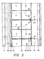
- FIG. 5 View A is shown in FIG. 5.
- the three trays 70 resting on the sleeper heads 43 are clearly visible here.
- Recesses 66, 67 are arranged on one side at the corners of the tubs 70, in which the profile elements are hooked.
- the tub 70 is divided by the ribs 50 and the side walls 45 into six fields for the - not shown here - receiving a plant substrate and for regulating the water level.
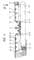
- FIG. 4 shows a further application of the device system according to the invention.
- another greening system with a tub 70 is shown in the right half of the figure, while on the left of the track center and resting on the sleeper head 43 or molded block 60, 5 other tubs 70 are arranged on the outside of the rail, the bottoms 51 of which form the surface of the device system .
- the system of tubs 70, plastic support strips 63, 72, clamping profile 33, ribs 50, support ledge 49 is identical in construction to the system according to FIG. 3.
- Only the base sleeves 52 show a closure in this application form of the tubs 70 to form a smooth surface 86 in the bottom 51, which - as mentioned - is designed as a predetermined breaking point and can be removed if necessary using a suitable tool.
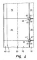
- View B is shown in FIG. 6.
- Three trays 70 and three further inverted trays 70 meet at two corner points in the middle of the track.
- a recess 66, 67 in each of the abutting corners of all tubs 70 form a composite, cloverleaf-like opening, into which a lock 65 consisting of four parallel, interconnected cylinders is inserted and thus holds four tubs 70 together.
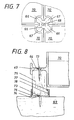
- FIG. 8 shows an embodiment of the mounting of the trough 70.
- a support strip 49 is provided on the center of the side wall 45, so that depending on the position of the trough 70 with the bottom 51 down or up the height.
- an alternative to the clamping profile 33 is arranged a clamping profile 76 with only one nose 77 made of plastic, in which a support strip 75 made of wood with a complementary thickening 78 which engages under the nose 77 after the insertion sits securely in position.
- a screw 73 in the bore 64 fastens the trough 70 on the support strip 44.
- the clamping profile 76 can be fastened by screw 73 in a bore 74 on the sleeper 69.
- Such attachment can be attached to every fifth, tenth or each tub, but is in any case necessary at the end of a tub system so that the last tub 70 is secured against removal from the track.
- a hole for a screw can be provided in the factory in each support bar. Otherwise, it is sufficient to attach the clamping profile to the sill by gluing, nailing or in some other way depending on the sleeper material and to attach the support strip and the tub without further attachment.
Landscapes
- Engineering & Computer Science (AREA)
- Architecture (AREA)
- Civil Engineering (AREA)
- Structural Engineering (AREA)
- Road Paving Structures (AREA)
- Cultivation Receptacles Or Flower-Pots, Or Pots For Seedlings (AREA)
- Manufacture, Treatment Of Glass Fibers (AREA)
- Replacement Of Web Rolls (AREA)
- Machines For Laying And Maintaining Railways (AREA)
Applications Claiming Priority (4)
| Application Number | Priority Date | Filing Date | Title |
|---|---|---|---|
| DE8911533U DE8911533U1 (de) | 1989-09-08 | 1989-09-08 | Bausatz für Begrünungssystem |
| DE8911533U | 1989-09-08 | ||
| DE4009479 | 1990-03-22 | ||
| DE4009479A DE4009479A1 (de) | 1989-09-08 | 1990-03-22 | Vorrichtungssystem zur abdeckung von gleisanlagen |
Publications (2)
| Publication Number | Publication Date |
|---|---|
| EP0420363A1 true EP0420363A1 (fr) | 1991-04-03 |
| EP0420363B1 EP0420363B1 (fr) | 1994-06-29 |
Family
ID=25891505
Family Applications (1)
| Application Number | Title | Priority Date | Filing Date |
|---|---|---|---|
| EP90250228A Expired - Lifetime EP0420363B1 (fr) | 1989-09-08 | 1990-09-07 | Système pour le recouvrement de voies ferrées |
Country Status (3)
| Country | Link |
|---|---|
| EP (1) | EP0420363B1 (fr) |
| AT (1) | ATE107983T1 (fr) |
| DE (2) | DE4009479A1 (fr) |
Cited By (11)
| Publication number | Priority date | Publication date | Assignee | Title |
|---|---|---|---|---|
| WO1993003303A1 (fr) * | 1991-07-30 | 1993-02-18 | Werner Haag | Systeme collecteur de substances organiques sous des vehicules sur rails |
| WO1993016230A1 (fr) * | 1992-02-13 | 1993-08-19 | Acappella Enterprises Ltd. | Systemes de suppression du bruit |
| EP0576939A1 (fr) * | 1992-06-25 | 1994-01-05 | RPS Recycling Produkte Systeme GmbH | Elément de construction à usage multiple en plastique |
| DE4434269A1 (de) * | 1994-09-24 | 1996-03-28 | Zueblin Ag | Micro-Lärmschutzwand |
| WO1996022423A1 (fr) * | 1995-01-20 | 1996-07-25 | Egon Turba | Element de voie ferree silencieux |
| DE19643533A1 (de) * | 1996-10-23 | 1998-04-30 | Krupp Ag Hoesch Krupp | Schallschutzauflage für Gleise |
| AT500911A1 (de) * | 2004-06-22 | 2006-04-15 | Gmundner Fertigteile Gmbh | Leiterschwellengleis |
| JP2007526412A (ja) * | 2004-03-05 | 2007-09-13 | グミュンドネル ファーチクタイル ゲゼルシャフト ミット ベシュレンクテル ハフトング ウント ツェーオー. カーゲー. | 騒音低減線路カバー |
| WO2010034048A1 (fr) * | 2008-09-24 | 2010-04-01 | Thera-S Di Kraus & Di (Fh) Maier Og | Système d'absorption du bruit pour superstructure de voie |
| CZ306897B6 (cs) * | 2016-01-26 | 2017-08-30 | Jan Eisenreich | Železniční nebo tramvajová kolej |
| CN109518548A (zh) * | 2018-12-05 | 2019-03-26 | 中国铁建重工集团有限公司 | 轨道保护装置 |
Families Citing this family (5)
| Publication number | Priority date | Publication date | Assignee | Title |
|---|---|---|---|---|
| DE4126694A1 (de) * | 1991-08-13 | 1993-02-18 | Gefinex Gmbh | Gartenzaun |
| DE4240650A1 (de) * | 1992-12-03 | 1994-06-09 | Patrick Schmidt | Solarkollektor mit Gehäuse- und Anschlußänderung |
| DE19710642A1 (de) * | 1997-03-17 | 1998-09-24 | Engelhardt Energiepark Gmbh | Sonnenkollektorgehäuse mit minimiertem Wirkungsgradverlust |
| CN112342860B (zh) * | 2020-11-10 | 2025-04-11 | 中铁第四勘察设计院集团有限公司 | 一种有轨电车地面区间绿篱植物布置结构 |
| DE202022105594U1 (de) | 2022-10-04 | 2022-11-03 | Martin Rose GmbH & Co. KG | Gleisanlage für Bahnfahrzeuge und Substratkomposition für eine solche Gleisanlage |
Citations (5)
| Publication number | Priority date | Publication date | Assignee | Title |
|---|---|---|---|---|
| DD77504A1 (fr) * | 1969-11-11 | 1970-11-05 | ||
| US4300721A (en) * | 1980-05-23 | 1981-11-17 | Oneida General Corporation | System for collecting liquid spillage at rail facilities |
| CH630681A5 (en) * | 1978-06-14 | 1982-06-30 | Alberto Vanoli | Track route upon which road vehicles can drive |
| DE8411436U1 (de) * | 1984-04-12 | 1984-07-26 | Weco Metall- und Maschinenbau GmbH, 5500 Trier | Vorrichtung zum auffangen von fluessigen schadstoffen an umschlagplaetzen im schienenbereich von schienenfahrzeugen |
| DE3737567A1 (de) * | 1986-12-18 | 1988-07-07 | Waagner Biro Ag | Laermschutzeinrichtung fuer eisenbahnstrecken |
-
1990
- 1990-03-22 DE DE4009479A patent/DE4009479A1/de not_active Withdrawn
- 1990-09-07 EP EP90250228A patent/EP0420363B1/fr not_active Expired - Lifetime
- 1990-09-07 DE DE59006300T patent/DE59006300D1/de not_active Expired - Fee Related
- 1990-09-07 AT AT90250228T patent/ATE107983T1/de active
Patent Citations (5)
| Publication number | Priority date | Publication date | Assignee | Title |
|---|---|---|---|---|
| DD77504A1 (fr) * | 1969-11-11 | 1970-11-05 | ||
| CH630681A5 (en) * | 1978-06-14 | 1982-06-30 | Alberto Vanoli | Track route upon which road vehicles can drive |
| US4300721A (en) * | 1980-05-23 | 1981-11-17 | Oneida General Corporation | System for collecting liquid spillage at rail facilities |
| DE8411436U1 (de) * | 1984-04-12 | 1984-07-26 | Weco Metall- und Maschinenbau GmbH, 5500 Trier | Vorrichtung zum auffangen von fluessigen schadstoffen an umschlagplaetzen im schienenbereich von schienenfahrzeugen |
| DE3737567A1 (de) * | 1986-12-18 | 1988-07-07 | Waagner Biro Ag | Laermschutzeinrichtung fuer eisenbahnstrecken |
Cited By (17)
| Publication number | Priority date | Publication date | Assignee | Title |
|---|---|---|---|---|
| WO1993003303A1 (fr) * | 1991-07-30 | 1993-02-18 | Werner Haag | Systeme collecteur de substances organiques sous des vehicules sur rails |
| US5492158A (en) * | 1991-07-30 | 1996-02-20 | Haag; Werner | System for collecting organic material underneath rail vehicles |
| WO1993016230A1 (fr) * | 1992-02-13 | 1993-08-19 | Acappella Enterprises Ltd. | Systemes de suppression du bruit |
| EP0576939A1 (fr) * | 1992-06-25 | 1994-01-05 | RPS Recycling Produkte Systeme GmbH | Elément de construction à usage multiple en plastique |
| DE4434269A1 (de) * | 1994-09-24 | 1996-03-28 | Zueblin Ag | Micro-Lärmschutzwand |
| WO1996022423A1 (fr) * | 1995-01-20 | 1996-07-25 | Egon Turba | Element de voie ferree silencieux |
| DE19501696A1 (de) * | 1995-01-20 | 1996-08-01 | Egon Turba | Geräuscharmer Gleiskörper |
| DE19643533C2 (de) * | 1996-10-23 | 2000-10-26 | Thyssen Krupp Materials & Serv | Begehbare und/oder befahrbare Abdeckung für Gleise mit Schallschutzelementen |
| DE19643533A1 (de) * | 1996-10-23 | 1998-04-30 | Krupp Ag Hoesch Krupp | Schallschutzauflage für Gleise |
| JP2007526412A (ja) * | 2004-03-05 | 2007-09-13 | グミュンドネル ファーチクタイル ゲゼルシャフト ミット ベシュレンクテル ハフトング ウント ツェーオー. カーゲー. | 騒音低減線路カバー |
| AT500911A1 (de) * | 2004-06-22 | 2006-04-15 | Gmundner Fertigteile Gmbh | Leiterschwellengleis |
| AT500911B1 (de) * | 2004-06-22 | 2006-10-15 | Gmundner Fertigteile Gmbh | Leiterschwellengleis |
| WO2010034048A1 (fr) * | 2008-09-24 | 2010-04-01 | Thera-S Di Kraus & Di (Fh) Maier Og | Système d'absorption du bruit pour superstructure de voie |
| CZ306897B6 (cs) * | 2016-01-26 | 2017-08-30 | Jan Eisenreich | Železniční nebo tramvajová kolej |
| US11021841B2 (en) | 2016-01-26 | 2021-06-01 | Jan Eisenreich | Railway or tramway track |
| CN109518548A (zh) * | 2018-12-05 | 2019-03-26 | 中国铁建重工集团有限公司 | 轨道保护装置 |
| CN109518548B (zh) * | 2018-12-05 | 2023-09-05 | 中国铁建重工集团股份有限公司 | 轨道保护装置 |
Also Published As
| Publication number | Publication date |
|---|---|
| DE59006300D1 (de) | 1994-08-04 |
| ATE107983T1 (de) | 1994-07-15 |
| DE4009479A1 (de) | 1991-03-28 |
| EP0420363B1 (fr) | 1994-06-29 |
Similar Documents
| Publication | Publication Date | Title |
|---|---|---|
| EP0420363B1 (fr) | Système pour le recouvrement de voies ferrées | |
| DE19641800A1 (de) | Modularer Bahnsteigbausatz | |
| AT391499B (de) | Eisenbahnoberbau, insbesondere fuer schienenfahrzeuge mit sehr hohen fahrgeschwindigkeiten | |
| EP0980931B2 (fr) | Procédé d'installation d'une voie ferrée | |
| DE4307260A1 (de) | Kabelkanalelement | |
| DE19503220A1 (de) | System für den schotterlosen Oberbau von Gleisanlagen | |
| EP0726359B1 (fr) | Voie de chemin de fer utilisée plus particulièrement sur terrain gazonné | |
| EP1644581B1 (fr) | Procédé de réalisation d'une structure de voie conçue pour des vehicles guides sur rails, en particulier des vehicules ferroviaires | |
| DE19848928C2 (de) | Feste Fahrbahn und Verfahren zu ihrer Herstellung | |
| DE102007046249A1 (de) | Gleiskörper mit geklebten Trögen | |
| DE4135445C2 (de) | Bahnsteigkante | |
| DE9003451U1 (de) | Bausatz für Abdeckung von Gleisanlagen | |
| CH623372A5 (en) | Track with flangeless lateral guidance for wheeled vehicles | |
| DE19741059C1 (de) | Verfahren zur Herstellung einer Festen Fahrbahn für schienengebundenen Verkehr, sowie eine Feste Fahrbahn zur Durchführung des Verfahrens | |
| DE3930498C1 (en) | Plant substrate for railway lines - has U=shaped rigid troughs inserted into track to support substrate | |
| DE4036232C2 (fr) | ||
| EP1106737A2 (fr) | Quai | |
| DE10158720C2 (de) | Fahrbahnplatte für Gleisanlagen | |
| DE9416319U1 (de) | Kanalsystem | |
| DE8706694U1 (de) | Lärmschutzwand | |
| DE3423566A1 (de) | Laermschutzschirm | |
| DE8911533U1 (de) | Bausatz für Begrünungssystem | |
| EP1253245A1 (fr) | Procédé d'utilisation alternative de voies ferrées | |
| DE1459763A1 (de) | Montierbare Strassen- und Wegeauflage | |
| DE4340787A1 (de) | Vorrichtung zum Auffangen von Schadstoffen im Schienenbereich |
Legal Events
| Date | Code | Title | Description |
|---|---|---|---|
| PUAI | Public reference made under article 153(3) epc to a published international application that has entered the european phase |
Free format text: ORIGINAL CODE: 0009012 |
|
| 17P | Request for examination filed |
Effective date: 19901210 |
|
| AK | Designated contracting states |
Kind code of ref document: A1 Designated state(s): AT BE CH DE DK FR GB IT LI LU NL SE |
|
| 17Q | First examination report despatched |
Effective date: 19921009 |
|
| GRAA | (expected) grant |
Free format text: ORIGINAL CODE: 0009210 |
|
| AK | Designated contracting states |
Kind code of ref document: B1 Designated state(s): AT BE CH DE DK FR GB IT LI LU NL SE |
|
| PG25 | Lapsed in a contracting state [announced via postgrant information from national office to epo] |
Ref country code: FR Effective date: 19940629 Ref country code: BE Effective date: 19940629 Ref country code: GB Effective date: 19940629 Ref country code: DK Effective date: 19940629 Ref country code: NL Effective date: 19940629 Ref country code: IT Free format text: LAPSE BECAUSE OF FAILURE TO SUBMIT A TRANSLATION OF THE DESCRIPTION OR TO PAY THE FEE WITHIN THE PRE;WARNING: LAPSES OF ITALIAN PATENTS WITH EFFECTIVE DATE BEFORE 2007 MAY HAVE OCCURRED AT ANY TIME BEFORE 2007. THE CORRECT EFFECTIVE DATE MAY BE DIFFERENT FROM THE ONE RECORDED.SCRIBED TIME-LIMIT Effective date: 19940629 |
|
| REF | Corresponds to: |
Ref document number: 107983 Country of ref document: AT Date of ref document: 19940715 Kind code of ref document: T |
|
| REF | Corresponds to: |
Ref document number: 59006300 Country of ref document: DE Date of ref document: 19940804 |
|
| PG25 | Lapsed in a contracting state [announced via postgrant information from national office to epo] |
Ref country code: SE Effective date: 19940929 |
|
| PG25 | Lapsed in a contracting state [announced via postgrant information from national office to epo] |
Ref country code: LU Free format text: LAPSE BECAUSE OF NON-PAYMENT OF DUE FEES Effective date: 19940930 |
|
| EN | Fr: translation not filed | ||
| NLV1 | Nl: lapsed or annulled due to failure to fulfill the requirements of art. 29p and 29m of the patents act | ||
| GBV | Gb: ep patent (uk) treated as always having been void in accordance with gb section 77(7)/1977 [no translation filed] |
Effective date: 19940629 |
|
| PLBE | No opposition filed within time limit |
Free format text: ORIGINAL CODE: 0009261 |
|
| STAA | Information on the status of an ep patent application or granted ep patent |
Free format text: STATUS: NO OPPOSITION FILED WITHIN TIME LIMIT |
|
| 26N | No opposition filed | ||
| PGFP | Annual fee paid to national office [announced via postgrant information from national office to epo] |
Ref country code: AT Payment date: 19960924 Year of fee payment: 7 |
|
| PGFP | Annual fee paid to national office [announced via postgrant information from national office to epo] |
Ref country code: CH Payment date: 19960930 Year of fee payment: 7 |
|
| PGFP | Annual fee paid to national office [announced via postgrant information from national office to epo] |
Ref country code: DE Payment date: 19961002 Year of fee payment: 7 |
|
| PG25 | Lapsed in a contracting state [announced via postgrant information from national office to epo] |
Ref country code: AT Free format text: LAPSE BECAUSE OF NON-PAYMENT OF DUE FEES Effective date: 19970907 |
|
| PG25 | Lapsed in a contracting state [announced via postgrant information from national office to epo] |
Ref country code: CH Free format text: LAPSE BECAUSE OF NON-PAYMENT OF DUE FEES Effective date: 19970930 Ref country code: LI Free format text: LAPSE BECAUSE OF NON-PAYMENT OF DUE FEES Effective date: 19970930 |
|
| REG | Reference to a national code |
Ref country code: CH Ref legal event code: PL |
|
| PG25 | Lapsed in a contracting state [announced via postgrant information from national office to epo] |
Ref country code: DE Free format text: LAPSE BECAUSE OF NON-PAYMENT OF DUE FEES Effective date: 19980603 |