EP0420501B1 - Gerät und Verfahren zur Feststellung der Lage eines Rotors in einem bürstenlosen Gleichstrommotor - Google Patents
Gerät und Verfahren zur Feststellung der Lage eines Rotors in einem bürstenlosen Gleichstrommotor Download PDFInfo
- Publication number
- EP0420501B1 EP0420501B1 EP90310301A EP90310301A EP0420501B1 EP 0420501 B1 EP0420501 B1 EP 0420501B1 EP 90310301 A EP90310301 A EP 90310301A EP 90310301 A EP90310301 A EP 90310301A EP 0420501 B1 EP0420501 B1 EP 0420501B1
- Authority
- EP
- European Patent Office
- Prior art keywords
- stator windings
- current
- pulse
- motor
- polarity
- Prior art date
- Legal status (The legal status is an assumption and is not a legal conclusion. Google has not performed a legal analysis and makes no representation as to the accuracy of the status listed.)
- Expired - Lifetime
Links
- 238000000034 method Methods 0.000 title claims description 24
- 238000004804 winding Methods 0.000 claims description 48
- 230000005284 excitation Effects 0.000 claims description 26
- 230000004044 response Effects 0.000 claims description 22
- 238000012544 monitoring process Methods 0.000 claims description 10
- 238000001514 detection method Methods 0.000 claims description 8
- 230000001939 inductive effect Effects 0.000 claims description 2
- 206010013710 Drug interaction Diseases 0.000 claims 1
- 230000008878 coupling Effects 0.000 claims 1
- 238000010168 coupling process Methods 0.000 claims 1
- 238000005859 coupling reaction Methods 0.000 claims 1
- 230000003993 interaction Effects 0.000 claims 1
- 230000004907 flux Effects 0.000 description 42
- 238000013459 approach Methods 0.000 description 11
- 230000010354 integration Effects 0.000 description 10
- 230000006870 function Effects 0.000 description 9
- 230000000694 effects Effects 0.000 description 6
- 238000005259 measurement Methods 0.000 description 6
- 238000010586 diagram Methods 0.000 description 4
- 230000008859 change Effects 0.000 description 3
- 230000008569 process Effects 0.000 description 3
- 230000005355 Hall effect Effects 0.000 description 2
- XEEYBQQBJWHFJM-UHFFFAOYSA-N Iron Chemical compound [Fe] XEEYBQQBJWHFJM-UHFFFAOYSA-N 0.000 description 2
- 230000004069 differentiation Effects 0.000 description 2
- 229920006395 saturated elastomer Polymers 0.000 description 2
- 230000002730 additional effect Effects 0.000 description 1
- 230000003247 decreasing effect Effects 0.000 description 1
- 230000006866 deterioration Effects 0.000 description 1
- 238000005516 engineering process Methods 0.000 description 1
- 238000002347 injection Methods 0.000 description 1
- 239000007924 injection Substances 0.000 description 1
- 229910052742 iron Inorganic materials 0.000 description 1
- 230000003287 optical effect Effects 0.000 description 1
- 230000010355 oscillation Effects 0.000 description 1
- 230000009291 secondary effect Effects 0.000 description 1
- 239000004065 semiconductor Substances 0.000 description 1
- 239000000243 solution Substances 0.000 description 1
- 230000003068 static effect Effects 0.000 description 1
- 230000001360 synchronised effect Effects 0.000 description 1
- 230000002277 temperature effect Effects 0.000 description 1
- 238000012360 testing method Methods 0.000 description 1
Images


Classifications
-
- H—ELECTRICITY
- H02—GENERATION; CONVERSION OR DISTRIBUTION OF ELECTRIC POWER
- H02P—CONTROL OR REGULATION OF ELECTRIC MOTORS, ELECTRIC GENERATORS OR DYNAMO-ELECTRIC CONVERTERS; CONTROLLING TRANSFORMERS, REACTORS OR CHOKE COILS
- H02P6/00—Arrangements for controlling synchronous motors or other dynamo-electric motors using electronic commutation dependent on the rotor position; Electronic commutators therefor
- H02P6/20—Arrangements for starting
- H02P6/22—Arrangements for starting in a selected direction of rotation
-
- H—ELECTRICITY
- H02—GENERATION; CONVERSION OR DISTRIBUTION OF ELECTRIC POWER
- H02P—CONTROL OR REGULATION OF ELECTRIC MOTORS, ELECTRIC GENERATORS OR DYNAMO-ELECTRIC CONVERTERS; CONTROLLING TRANSFORMERS, REACTORS OR CHOKE COILS
- H02P6/00—Arrangements for controlling synchronous motors or other dynamo-electric motors using electronic commutation dependent on the rotor position; Electronic commutators therefor
- H02P6/14—Electronic commutators
- H02P6/16—Circuit arrangements for detecting position
- H02P6/18—Circuit arrangements for detecting position without separate position detecting elements
- H02P6/185—Circuit arrangements for detecting position without separate position detecting elements using inductance sensing, e.g. pulse excitation
Definitions
- the present invention relates to a method and apparatus for detecting the rotor position of a brushless DC motor when the motor is stopped, without the use of known rotor position detecting elements such as Hall sensors.
- the method and apparatus may be applied to any type of motor having an excitation flux created by a permanent magnet or by DC current excitation of a winding.
- the position of magnetic poles of the rotor are conventionally detected by means of a detector directly coupled to the shaft of the rotor.
- semi-conductor switching elements such as transistors, thyristors or the like, are turned on and off so as continuously to generate torque in the motor.
- Field windings or a multi-segment permanent magnet is used for the rotor.
- the torque is created by the application of DC current to stator or field windings or phases in sequential order to produce a torque-inducing flux for moving the rotor.
- the DC current is alternately switched about the field windings to create various current paths that produce magnetic flux orientations in a synchronised fashion.
- the magnetic flux so produced results in a torque on the rotor that causes the desired rotational movement.
- sensing devices are used to provide information about the position of the rotor. Typically, this information is derived through devices such as Hall sensors (Hall effect devices), optical sensors or resolvers. These do not give an absolute position, but supply enough information in order to know the relative position of the rotor in one electrical period. Therefore, it is possible using these devices to energize the motor in such a way that it starts in every case in the correct direction.
- Hall effect sensors the best known and most commonly used, especially in motors where economy and small size are of significant importance, are Hall effect sensors.
- the position of the Hall sensors must be very precisely fixed.
- the heat resisting temperature of a Hall sensor is limited, so that deterioration of the characteristics of the motor can occur if the motor is heavily loaded.
- Another problem with these sensing devices is that they more prone to failure than most of the apparatus in which they are used.
- the Hall sensor significantly affects the overall reliability of the apparatus that incorporates the sensing device.
- incorporating these sensing devices in the motor structure itself increases the motor size, cost, complexity and power consumption.
- a number of wire leads must also be provided to each Hall sensor to bring out the information detected by the Hall sensor to a micro-processor or the like external to the motor shell.
- EP-A-251,785 One known effort to determine the starting position without the use of sensors is disclosed in EP-A-251,785. According to this method, a short current pulse is applied to each phase of the motor, and the resulting motor current is measured to determine the positional information of the rotor based on the return pulse of greatest amplitude.
- the difference between the pulses returned from the different phases may be very small, and may be affected by temperature, differences between the phase inductances, phase resistances, or the use of a relatively high frequency which can create eddy currents.
- apparatus for detecting the position of a rotor of a brushless DC motor comprising a driver for applying electrical pulses to stator windings of the motor, and monitoring means for detecting the electrical signal generated in the stator windings in response to said electrical pulses, characterised in that the driver is arranged to apply both a electrical pulse of one polarity and a electrical pulse of an opposite polarity to different ones or sets of the stator windings in succession, and in that there are provided comparison means for determining for each said one or set of the stator windings the sign of the difference between a first value representing the electrical signal detected by the monitoring means in response to said electrical pulse of one polarity and a second value representing the electrical signal detected by the monitoring means in response said electrical pulse of an opposite polarity, and means for identifying the position of the rotor on the basis of outputs from the comparison means.
- a method for detecting the position of a rotor of a brushless DC motor comprising the steps of applying electrical pulses to stator windings of the motors detecting the electrical signal generated in the stator windings in response to said electrical pulses, and determining the position of the rotor on the basis of the detected electrical signal, and characterised in that the step of applying comprises applying both a electrical pulse of one polarity and a electrical pulse of an opposite polarity to different ones or sets of the stator windings in succession, and in that the step of determining comprises determining for each said one or set of the stator windings the sign of the difference between a first value representing the electrical signal detected in response to said electrical pulse of one polarity and a second value representing the electrical signal detected in response to said electrical pulse of an opposite polarity, and identifying the position of the rotor on the basis of the signs determined.
- a closed loop mode may be switched on, using a dynamic indirect position detection as is already well known in the technology.
- the position at start is determined by the injection of short electrical pulses in different motor phases, each phase or set of phases being energised first by a pulse of one polarity and then by a pulse of the opposite polarity.
- the sign of the differences of the pulses injected in the same phase or set of phases is detected, for example by detecting the sign of the difference in the induced voltages.
- This technique in effect, indirectly detects the saturation level of the different motor phases.
- the measurement is made in such a way that the influence of the temperature on the electrical time constants and the different possible variations in winding parameters do not affect the final detection of the motor position. Starting in the correct direction is thus assured, and can be achieved without back oscillation.
- the present invention may be used in a motor such as that shown in U. S. Application Serial No. 115,268, filed on October 30, 1987.
- Any polarized motor such as a brushless DC motor, including permanent magnets or excitation windings, has a local stator and rotor saturation level.
- phase inductances are a function of rotor position.
- the approach taken in the present invention is to measure the saturation level of the phase flux versus the current in a phase for each corresponding phase in such a way that the following parameters cannot influence measurement accuracy:
- the method disclosed below and the apparatus used to implement it provide a reliable and efficient approach to determining the starting position for a motor, particularly a small power motor.
- the total flux ⁇ phase can be increased or decreased by the current effect, thus modifying the saturation level.
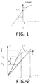
- FIG 1 represents the two possible cases for a given position when motor is in a standstill state.
- phase current can be written as:
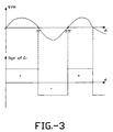
- FIG 2 shows the two different currents, where current i- is represented by its absolute value.
- the sign of the current difference ⁇ i is a characteristic of the current effect superimposed to the excitation flux ⁇ PM effect. Three cases have to be considered:
- ⁇ i is greater than zero, it means that the current i + creates a flux of the same direction as the excitation flux created by the permanent-magnet (or the DC current excitation winding flux).
- the current i - creates a flux of opposite direction, to the excitation flux.
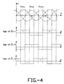
- FIG 3 shows the correlation between the excitation flux ⁇ PM and the sign of the current difference ⁇ i versus the rotor position (motor at standstill).
- the measurements of the current difference ⁇ i in each phase permits to determine the rotor position with an accuracy of ⁇ /3 ⁇ 60 electrical degrees.
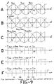
- FIG 4 shows such a configuration, and the correlation between the different excitation flux ⁇ PM and the corresponding current differences ⁇ i, for a three-phase motor.
- a decision on rotor position can be made based on the difference in the current integration Aii rather than the difference in the current Ai.
- FIG 5 shows the corresponding currents and the difference of the current integration Aii. This figure illustrates that integration emphasizes the difference between the flux induced by the currents of opposite direction, and thereby enhances the accuracy of the method. Thus, integration is considered the preferred approach, which gives the most accurate results.
- the sign of ⁇ di permits determination of the rotor position similarly to the approach defined when using the sign of the current difference Ai.
- FIG 7 An example of the process used to measure motor position at standstill using the method of the present invention is given with respect to FIG 7 for a three-phase motor.
- the process as described in the apparatus and step shown are not intended to be exhaustive, but merely as an example.
- each phase of a motor 14 is supplied first with a positive current through the driver 12.
- the resulting current is converted to a voltage through a current voltage converter 16.
- Each phase is supplied the current for a time T.
- the final value of the current, after time T, is stored by use of a switch 18 in a peak detector 20.
- the same phase is now energized using a negative current through driver 12, and the resulting current converted to a voltage at converter 16 and through switch 18 stored at peak detector 22.
- the two peak current values are compared at comparator 24, with the difference in magnitude not being established, but only the sign of the magnitude.
- the sign of the current difference is routed via switch 26 to a memory 28.
- the measurement of the current difference is made when two phases in series are energized for each possible configuration. These configurations are Phase 1 and Phase 2 in series; Phase 1 and Phase 3 in series; and Phase 2 and Phase 3 in series.
- the first combination of Phase 1 and Phase 2 is energized to cause a current to pass therethrough by turning on transistors G1 and G5, causing the current to pass from G1 through Phase 1 to Phase 2 and through the resistor R6 to ground, with the current being measured at the point A.
- transistors G2, G4 are switched off, and a current in the opposite direction is caused to pass through the same series pair of phases by turning on transistors G2, G4 with the current being measured at the same point.
- the difference in the currents is then determined either by subtraction of the values, or by first integration and then determination of the difference, or differentiation and determination of the difference, all as explained as above.
- the difference is stored as a one or zero representing positive or negative.
- the convention to be adopted in explaining this specific example is that if the signs of the current difference is positive, the function will be considered to be equal to be one; if the sign of the current difference is negative, then the function is considered to be equal to zero.
- the remaining current differences for the phase configuration are measured by appropriate switching of the transistor G1-G6.
- the top line, Line A represents the different excitation flux in the phases, ⁇ PM1, A PM2, ⁇ PM3, versus the motor rotor position.
- the second line, Line B represents the different phase torques, T1, T2, T3, and thereby illustrates the static torque which can be created.
- the third line, line C shows the flux differences, the first difference f PM1 - f PM2, the second difference ⁇ PM2 - f PM3, the third difference ⁇ PM3 - f PM1.
- the fourth line, Line D represents the current difference ⁇ i1.
- the fifth line, Line E represents the current difference sign Ai2.
- the sixth line, Line F represents the current difference sign Ai3.
- the torque is then determined as follows:
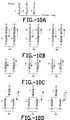
- FIG 10C currents run in opposite directions through one phase at a time.
- the current difference ( * ) is measured between each phase and the center tap.
- a combination of phases comprising a phase connected in series with the two other phases connected in parallel.
- the current difference ( * ) is then measured as indicated between the phase combination and the center tap.
Landscapes
- Engineering & Computer Science (AREA)
- Power Engineering (AREA)
- Control Of Motors That Do Not Use Commutators (AREA)
- Brushless Motors (AREA)
Claims (10)
dadurch gekennzeichnet, daß die Überwachungseinrichtungen einen Strom-/Spannungswandler (16), der so ausgebildet ist, daß er mit jeder der Statorwicklungen oder dem Satz von Statorwicklungen verbindbar ist, und Spitzenspannungs-Detektoreinrichtungen (20, 22) zur Feststellung eines Spitzenspannungs-Ausgangssignals von dem Strom-/Spannungswandler in Abhängigkeit von der Zuführung jedes der Impulse umfassen.
dadurch gekennzeichnet, daß die Überwachungseinrichtungen Einrichtungen zur Integration des festgestellten Signals zur Lieferung der ersten und zweiten Werte umfassen.
dadurch gekennzeichnet, daß die Überwachungseinrichtungen Einrichtungen zum Differenzieren des festgestellten Signals zur Lieferung der ersten und zweiten Werte umfassen.
dadurch gekennzeichnet, daß der Schritt der Zuführung der Impulse die Zuführung sowohl eines elektrischen Impulses mit einer Polarität als auch eines elektrischen Impulses mit einer entgegengesetzten Polarität an verschiedene der Statorwicklungen oder Sätze der Statorwicklungen in einer Folge umfaßt, und daß der Schritt der Bestimmung der Position die Bestimmung, für jede der Statorwicklungen oder den Satz von Statorwicklungen, des Vorzeichens der Differenz zwischen einem ersten Wert, der das in Abhängigkeit von dem Impuls mit einer Polarität festgestellte elektrische Signal darstellt, und einem zweiten Wert, der das elektrische Signal darstellt, das in Abhängigkeit von dem Impuls mit einer entgegengesetzten Polarität festgestellt wird, sowie die Identifikation der Position des Rotors auf der Grundlage der festgestellten Vorzeichen umfaßt.
dadurch gekennzeichnet, daß der Schritt derZuführung der Impulse die Zuführung des Impulses mit einer Polarität und des Impulses mit der entgegengesetzten Polarität an jeweilige Serienverbindungen der Statorwicklungen in einer Folge umfaßt.
dadurch gekennzeichnet, daß der Schritt derZuführung der Impulse die Zuführung des Impulses mit einer Polarität und des Impulses mit einer entgegengesetzten Polarität an jeweilige Sätze der Statorwicklungen in einer Folge umfaßt, wobei jeder Satz eine erste Statorwicklung umfaßt, die in Serie mit zwei zueinander parallel geschalteten Statorwicklungen geschaltet ist.
dadurch gekennzeichnet, daß der Schritt derZuführung der Impulse die Zuführung des Impulses mit einer Polarität und des Impulses mit einer entgegengesetzten Polarität zunächst an jede jeweilige der Statorwicklungen und danach an jeweilige in Serie geschaltete Paare von Statorwicklungen umfaßt.
dadurch gekennzeichnet, daß Treibereinrichtungen (12) mit der Vielzahl von Statorwicklungen zurZuführung von elektrischen Kurzzeit-Impulsen, zunächst mit einer Polarität und dann mit einer entgegengesetzten Polarität an zumindestens eine Phase hiervon verbunden sind, um zumindestens ein zweites gesteuertes Magnetfeld zu induzieren, daß Überwachungseinrichtungen (16,20,22) zur Feststellung jedes elektrischen Signals vorgesehen sind, das durch die angelegten Impulse ausgebildet wird, wobei jedes derartige Signal eine Wechselwirkung des ersten festen Magnetfeldes und des zweiten gesteuerten Magnetfeldes darstellt, daß Vergleichereinrichtungen (24) zur Bestimmung des Vorzeichens der Differenz zwischen der Antwort auf den Impuls mit der ersten Polarität und der Antwort auf den Impuls mit der zweiten entgegengesetzten Polarität für jede der zumindestens einen angesteuerten Phase vorgesehen sind, und daß Detektoreinrichtungen (34) zur Identifikation der Drehposition des Magneten relativ zu den Statorwicklungen auf der Grundlage des Vorzeichens der Differenz zwischen den Antworten auf die Impulse vorgesehen sind.
Applications Claiming Priority (2)
| Application Number | Priority Date | Filing Date | Title |
|---|---|---|---|
| US413311 | 1989-09-27 | ||
| US07/413,311 US5001405A (en) | 1989-09-27 | 1989-09-27 | Position detection for a brushless DC motor |
Publications (2)
| Publication Number | Publication Date |
|---|---|
| EP0420501A1 EP0420501A1 (de) | 1991-04-03 |
| EP0420501B1 true EP0420501B1 (de) | 1995-02-01 |
Family
ID=23636754
Family Applications (1)
| Application Number | Title | Priority Date | Filing Date |
|---|---|---|---|
| EP90310301A Expired - Lifetime EP0420501B1 (de) | 1989-09-27 | 1990-09-20 | Gerät und Verfahren zur Feststellung der Lage eines Rotors in einem bürstenlosen Gleichstrommotor |
Country Status (4)
| Country | Link |
|---|---|
| US (1) | US5001405A (de) |
| EP (1) | EP0420501B1 (de) |
| JP (1) | JPH0813196B2 (de) |
| DE (1) | DE69016550T2 (de) |
Families Citing this family (94)
| Publication number | Priority date | Publication date | Assignee | Title |
|---|---|---|---|---|
| US5028852A (en) * | 1990-06-21 | 1991-07-02 | Seagate Technology, Inc. | Position detection for a brushless DC motor without hall effect devices using a time differential method |
| US5117165A (en) * | 1990-06-29 | 1992-05-26 | Seagate Technology, Inc. | Closed-loop control of a brushless DC motor from standstill to medium speed |
| US5235264A (en) * | 1990-06-30 | 1993-08-10 | Nippon Densan Corporation | Method of and circuit for starting sensorless motor |
| US5703449A (en) * | 1990-10-19 | 1997-12-30 | Seiko Epson Corporation | Controller for brushless DC motor without position sensor |
| US5245256A (en) * | 1991-02-15 | 1993-09-14 | Seagate Technology, Inc. | Closed loop control of a brushless DC motor at nominal speed |
| US5191270A (en) * | 1991-06-07 | 1993-03-02 | Sgs-Thomson Microelectronics, Inc. | Method for starting a motor |
| US5223771A (en) * | 1991-06-17 | 1993-06-29 | Western Digital (Singapore) Pte., Ltd. | Polyphase brushless DC Motor control |
| US5323094A (en) * | 1992-02-24 | 1994-06-21 | Nippon Densen Corporation | Method of starting a sensorless multiphase dc motor |
| US5576910A (en) * | 1993-06-04 | 1996-11-19 | Cirrus Logic, Inc. | Burst comparison and sequential technique for determining servo control in a mass storage disk device |
| US5477103A (en) * | 1993-06-04 | 1995-12-19 | Cirrus Logic, Inc. | Sequence, timing and synchronization technique for servo system controller of a computer disk mass storage device |
| US5557180A (en) * | 1993-06-30 | 1996-09-17 | Sgs-Thomson Microelectronics, Inc. | Circuit and method for operating a 3-phase motor with a uni-coil phase commutation scheme |
| US5384524A (en) * | 1993-09-02 | 1995-01-24 | Cirrus Logic, Inc. | Voice coil motor control circuit and method for servo system control in a computer mass storage device |
| US5448149A (en) * | 1994-06-20 | 1995-09-05 | Texas A&M University | Indirect rotor position sensor for a sinusoidal synchronous reluctance machine |
| US5497064A (en) * | 1995-03-14 | 1996-03-05 | A. O. Smith Corporation | Apparatus for starting a switched reluctance motor |
| US5537019A (en) * | 1995-03-14 | 1996-07-16 | A. O. Smith Corporation | Switched reluctance motor providing rotor position detection at high speeds without a separate rotor shaft position sensor |
| US5525887A (en) * | 1995-03-14 | 1996-06-11 | A. O. Smith Corporation | Switched reluctance motor providing rotor position detection at low speeds without a separate rotor shaft position sensor |
| US5841252A (en) * | 1995-03-31 | 1998-11-24 | Seagate Technology, Inc. | Detection of starting motor position in a brushless DC motor |
| US5569990A (en) * | 1995-03-31 | 1996-10-29 | Seagate Technology, Inc. | Detection of starting motor position in a brushless DC motor |
| AT405352B (de) * | 1995-05-30 | 1999-07-26 | Lst Laser & Strahl Gmbh | Verfahren zur läuferpositionsbestimmung für einen rotations- oder linear-motor und schaltungsanordnung zur durchführung dieses verfahrens |
| US5838122A (en) * | 1996-02-08 | 1998-11-17 | Seiberco Incorporated | Motor initialization method and apparatus |
| US6051942A (en) * | 1996-04-12 | 2000-04-18 | Emerson Electric Motor Co. | Method and apparatus for controlling a switched reluctance machine |
| US5744921A (en) * | 1996-05-02 | 1998-04-28 | Siemens Electric Limited | Control circuit for five-phase brushless DC motor |
| US5675464A (en) * | 1996-05-02 | 1997-10-07 | Siemens Electric Limited | Stall or reduced-speed protection system for electric motor |
| US6091222A (en) * | 1997-06-30 | 2000-07-18 | Stmicroelectronics, Inc. | Statistical phase detection and go start-up algorithm |
| US5998946A (en) * | 1997-10-08 | 1999-12-07 | Daewoo Electronics Co., Ltd. | Method and apparatus for controlling a rotation of a sensorless and brushless DC motor |
| DE19838227A1 (de) * | 1998-08-22 | 2000-02-24 | Frankl & Kirchner | Verfahren zur Bestimmung der Rotorlage eines Synchronmotors |
| DE69909449T2 (de) * | 1999-04-23 | 2004-04-15 | Stmicroelectronics S.R.L., Agrate Brianza | Antriebssystem für bürstenlosem Motor mit Hallsensoren und selbsttätiger Bestimmung der Phasenlage der instalierten Sensoren |
| KR20010079868A (ko) * | 1999-07-20 | 2001-08-22 | 요트.게.아. 롤페즈 | 브러시리스 모터를 위한 센서리스 제어 유닛 및 이 제어유닛을 포함하는 기록/판독 장치 |
| ES2252043T3 (es) * | 1999-08-17 | 2006-05-16 | Black & Decker Inc. | Control de una maquina electrica de reclutancia. |
| WO2001045247A1 (en) * | 1999-12-14 | 2001-06-21 | The Penn State Research Foundation | Detection of rotor angle in a permanent magnet synchronous motor at zero speed |
| JP3673964B2 (ja) * | 2000-03-29 | 2005-07-20 | 株式会社ルネサステクノロジ | ブラシレスモータ駆動制御用半導体集積回路およびブラシレスモータ駆動制御装置 |
| US6369534B1 (en) | 2000-04-26 | 2002-04-09 | Stmicroelectronics, Inc. | Circuit and method for detecting backward spin of a spindle motor for a disk drive |
| US6437525B1 (en) | 2000-08-18 | 2002-08-20 | Stmicroelectronics, Inc. | Method and apparatus for spinning a multiphase motor for a disk drive system from an inactive state |
| US6598000B1 (en) | 2000-08-18 | 2003-07-22 | Stmicroelectronics, Inc. | Method and apparatus for detecting motion of a motor for a disk drive system |
| JP3979561B2 (ja) * | 2000-08-30 | 2007-09-19 | 株式会社日立製作所 | 交流電動機の駆動システム |
| US6710567B2 (en) | 2000-11-27 | 2004-03-23 | Seagate Technology Llc | Velocity dependent reference profile for spindle motor acceleration control |
| US6541928B2 (en) | 2000-12-29 | 2003-04-01 | Stmicroelectronics, Inc. | Adaptive system and method for spinning a polyphase disk drive motor from a stationary position |
| GB0100552D0 (en) * | 2001-01-09 | 2001-02-21 | Switched Reluctance Drives Ltd | A method and system for determining rotor position in a switched reluctance machine |
| US6577088B2 (en) | 2001-02-09 | 2003-06-10 | Seagate Technology Llc | Closed loop spindle motor acceleration control in a disc drive |
| US6664749B2 (en) | 2001-04-06 | 2003-12-16 | Seagate Technology Llc | Spindle motor initialization after a control processor reset condition in a disc drive |
| US6744587B2 (en) | 2001-06-29 | 2004-06-01 | Seagate Technology Llc | Motor control circuit with adaptive controller path selection for different load conditions |
| US6707269B2 (en) | 2001-09-11 | 2004-03-16 | Seagate Technology Llc | Motor control circuit with adaptive dynamic range selection |
| JP3998960B2 (ja) * | 2001-12-12 | 2007-10-31 | 株式会社ルネサステクノロジ | センサレスモータ駆動制御システム |
| DE10162380A1 (de) * | 2001-12-19 | 2003-07-03 | Bosch Gmbh Robert | Verfahren zum Starten eines bürstenlosen Gleichstrommotors |
| US7012391B2 (en) * | 2002-08-09 | 2006-03-14 | Seagate Technology Llc | Motor acceleration using continuous sequence of current limit values |
| AU2003289936A1 (en) * | 2002-08-20 | 2004-03-11 | Seagate Technology Llc | Rotor position determination for a multi-phase motor |
| FR2844403B1 (fr) * | 2002-09-05 | 2004-12-17 | Alstom | Procede et calculateur de determination de la position angulaire a l'arret d'un rotor, unite de commande et systeme incorporant ce calculateur |
| US7023155B2 (en) * | 2003-06-05 | 2006-04-04 | Seagate Technology Llc | Spindle motor acceleration control |
| US7404073B2 (en) * | 2003-06-26 | 2008-07-22 | Seagate Technology Llc | Transitioning from startup code to application code during initialization of a processor based device |
| US7514887B2 (en) * | 2003-10-24 | 2009-04-07 | A. O. Smith Corporation | Electrical machine and method of controlling the same |
| JP4263582B2 (ja) * | 2003-11-17 | 2009-05-13 | 本田技研工業株式会社 | ブラシレスモータ制御装置 |
| TW200616321A (en) | 2004-05-24 | 2006-05-16 | Rohm Co Ltd | Rotation control apparatus and method, and electronic device wherein the rotation control apparatus can be used |
| JP4455981B2 (ja) * | 2004-11-30 | 2010-04-21 | 株式会社日立産機システム | 同期電動機の駆動装置 |
| DE102005007995A1 (de) * | 2005-02-22 | 2006-08-31 | Robert Bosch Gmbh | Rotorlagendetektion |
| US7855523B2 (en) | 2005-06-20 | 2010-12-21 | Rohm Co., Ltd. | Motor driving circuit and disc apparatus using the same |
| US7652441B2 (en) * | 2005-07-01 | 2010-01-26 | International Rectifier Corporation | Method and system for starting a sensorless motor |
| JP4745745B2 (ja) * | 2005-07-21 | 2011-08-10 | パナソニック株式会社 | モータ駆動装置及びモータ駆動方法 |
| GB0517907D0 (en) * | 2005-09-02 | 2005-10-12 | Melexis Gmbh | Improvements in or relating to driving brushless DC (BLDC) motors |
| JP4860980B2 (ja) | 2005-10-20 | 2012-01-25 | ローム株式会社 | モータ駆動回路およびそれを用いたディスク装置 |
| DE102006004166A1 (de) * | 2006-01-30 | 2007-08-02 | Robert Bosch Gmbh | Verfahren und Schaltungsanordnung zur Bestimmung der Rotorlage eines EC-Motors im Stillstand |
| JP4880339B2 (ja) * | 2006-03-29 | 2012-02-22 | ローム株式会社 | モータ駆動回路および方法ならびにそれを用いたディスク装置 |
| KR101322985B1 (ko) | 2006-03-29 | 2013-10-29 | 로무 가부시키가이샤 | 모터 구동 회로, 방법 및 이를 이용한 디스크 장치 |
| JP4877764B2 (ja) | 2006-08-01 | 2012-02-15 | ローム株式会社 | モータ駆動回路、方法およびそれらを用いたディスク装置 |
| US7334854B1 (en) * | 2006-09-20 | 2008-02-26 | Aimtron Technology Corp. | Sensorless start-up method for driving a brushless DC motor |
| JP4632157B2 (ja) * | 2006-12-04 | 2011-02-16 | 日立アプライアンス株式会社 | 永久磁石モータの駆動システム |
| JP4963246B2 (ja) * | 2007-03-16 | 2012-06-27 | ローム株式会社 | モータ駆動回路、駆動方法ならびにそれらを用いたディスク装置 |
| JP5171079B2 (ja) * | 2007-03-16 | 2013-03-27 | ローム株式会社 | モータ駆動回路、駆動方法ならびにそれらを用いたディスク装置 |
| US7855521B2 (en) | 2007-03-16 | 2010-12-21 | Rohm Co., Ltd. | Motor drive circuit |
| GB0717851D0 (en) * | 2007-09-13 | 2007-10-24 | Melexis Nv | Improvements relating to driving brushless dc (bldc) motors |
| GB0722740D0 (en) * | 2007-11-20 | 2008-01-02 | Melexis Nv | Improvements in or relating to bldc motors |
| JP5566044B2 (ja) | 2008-05-22 | 2014-08-06 | ローム株式会社 | モータ駆動回路および駆動方法、および波形データの生成方法、それらを利用したハードディスク装置 |
| CA2725818C (en) * | 2008-06-02 | 2013-12-31 | Dentsply International Inc. | Methods for designing a customized dental prosthesis using digital images of a patient |
| JPWO2009150794A1 (ja) | 2008-06-13 | 2011-11-10 | ローム株式会社 | モータ駆動回路 |
| GB0815672D0 (en) * | 2008-08-28 | 2008-10-08 | Melexis Nv | Improvements of accuracy of rotor position detection relating to the control of brushless dc motors |
| GB0822515D0 (en) * | 2008-12-10 | 2009-01-14 | Melexis Nv | Operation of BLDC motors |
| TWI382650B (zh) * | 2009-01-22 | 2013-01-11 | Richtek Techohnology Corp | 永磁式同步馬達的轉子位置偵測裝置及方法 |
| CN101800509B (zh) * | 2009-02-10 | 2013-09-18 | 立锜科技股份有限公司 | 永磁式同步马达的转子位置检测装置及方法 |
| GB0916543D0 (en) * | 2009-09-21 | 2009-10-28 | Melexis Tessenderlo Nv | Control of sinusoidally driven brushless dc (bldc) motors |
| JP5594160B2 (ja) * | 2011-01-20 | 2014-09-24 | 株式会社豊田自動織機 | 電動モータ内蔵磁石の劣化検知方法及び装置 |
| US8901867B2 (en) | 2011-04-28 | 2014-12-02 | Regal Beloit America, Inc. | Electrical machine, method of controlling an electrical machine, and system including an electrical machine |
| JP5997458B2 (ja) | 2012-02-22 | 2016-09-28 | ローム株式会社 | 回転制御装置及び方法、並びに、これを用いたディスク駆動装置 |
| JP5970227B2 (ja) * | 2012-04-17 | 2016-08-17 | 日立オートモティブシステムズ株式会社 | 同期電動機の駆動システム |
| EP2951918B1 (de) | 2013-01-09 | 2021-06-16 | NXP USA, Inc. | Vorrichtung zur bestimmung einer position eines rotors eines mehrphasigen elektromotors |
| TWI485972B (zh) | 2013-01-31 | 2015-05-21 | Rhymebus Corp | 馬達轉子角度偵測模組及其方法 |
| US9559623B2 (en) | 2013-08-30 | 2017-01-31 | Regal Beloit America, Inc. | Method of controlling an electrical machine |
| US10312847B2 (en) | 2016-05-09 | 2019-06-04 | Allegro Microsystems, Llc | Motor control using phase current and phase voltage |
| US10181810B2 (en) | 2016-06-16 | 2019-01-15 | Allegro Microsystems, Llc | Determining motor position with complementary driving and detection and current injection |
| US10116243B2 (en) | 2016-06-16 | 2018-10-30 | Allegro Microsystems, Llc | Determining motor position with complementary drive and detect and slight move |
| EP3264586B1 (de) * | 2016-06-28 | 2020-04-29 | STMicroelectronics Design and Application s.r.o. | Verfahren zur steuerung von elektromotoren, zugehörige vorrichtung und motor |
| JP7152875B2 (ja) * | 2018-05-16 | 2022-10-13 | キヤノン株式会社 | モータ制御装置及び画像形成装置 |
| GB2579184B (en) | 2018-11-22 | 2022-02-09 | Dyson Technology Ltd | A method of controlling a brushless permanent magnet motor |
| US11303235B2 (en) | 2019-04-25 | 2022-04-12 | Black & Decker Inc. | Dual-controller system for a sensorless brushless motor control |
| EP3751723A1 (de) | 2019-06-10 | 2020-12-16 | Black & Decker Inc. | Feldorientierte steuerung eines sensorlosen bürstenlosen motors in einem elektrowerkzeug |
| CN112511062B (zh) * | 2020-10-23 | 2022-06-17 | 中颖电子股份有限公司 | 一种永磁同步电机启动及低速运行方法 |
Family Cites Families (8)
| Publication number | Priority date | Publication date | Assignee | Title |
|---|---|---|---|---|
| JPS61132064A (ja) * | 1984-11-29 | 1986-06-19 | Sony Corp | ブラシレスモ−タ |
| DE3602227A1 (de) * | 1986-01-25 | 1987-07-30 | Philips Patentverwaltung | Kommutierungsschaltung fuer einen kollektorlosen gleichstrommotor |
| US4876491A (en) * | 1986-07-01 | 1989-10-24 | Conner Peripherals, Inc. | Method and apparatus for brushless DC motor speed control |
| JP2547778B2 (ja) * | 1986-07-01 | 1996-10-23 | コナ− ペリフエラルズ インコ−ポレ−テツド | ブラシレス直流モ−タおよび該モ−タの制御方法 |
| EP0282598B1 (de) * | 1986-08-06 | 1993-03-17 | Fujitsu Limited | Gleichstrommotorantriebssystem |
| US4678973A (en) * | 1986-10-07 | 1987-07-07 | General Motors Corporation | Sensorless starting control for a brushless DC motor |
| US4673849A (en) * | 1986-10-10 | 1987-06-16 | Allied Corporation | Permanent magnet motor closed loop restarting system |
| GB2208190B (en) * | 1987-07-09 | 1991-06-05 | Johnson Electric Ind Mfg | Brushless electric motor |
-
1989
- 1989-09-27 US US07/413,311 patent/US5001405A/en not_active Expired - Lifetime
-
1990
- 1990-09-20 EP EP90310301A patent/EP0420501B1/de not_active Expired - Lifetime
- 1990-09-20 DE DE69016550T patent/DE69016550T2/de not_active Expired - Fee Related
- 1990-09-26 JP JP2256784A patent/JPH0813196B2/ja not_active Expired - Fee Related
Also Published As
| Publication number | Publication date |
|---|---|
| DE69016550T2 (de) | 1995-06-01 |
| EP0420501A1 (de) | 1991-04-03 |
| JPH0813196B2 (ja) | 1996-02-07 |
| DE69016550D1 (de) | 1995-03-16 |
| JPH03207250A (ja) | 1991-09-10 |
| US5001405A (en) | 1991-03-19 |
Similar Documents
| Publication | Publication Date | Title |
|---|---|---|
| US5001405A (en) | Position detection for a brushless DC motor | |
| US5028852A (en) | Position detection for a brushless DC motor without hall effect devices using a time differential method | |
| US4992710A (en) | Position detection for a brushless DC motor with sample time optimization | |
| US5254914A (en) | Position detection for a brushless DC motor without Hall effect devices using a mutual inductance detection method | |
| EP0517393B1 (de) | Verfahren zur Bestimmung der Anlaufrichtung eines bürstenlosen, mehrphasigen Gleichstrommotors und Steuerungssystem dafür | |
| US5117165A (en) | Closed-loop control of a brushless DC motor from standstill to medium speed | |
| US5525886A (en) | Low speed position estimator for switched reluctance machine using flux/current model | |
| US5841252A (en) | Detection of starting motor position in a brushless DC motor | |
| US5569990A (en) | Detection of starting motor position in a brushless DC motor | |
| KR970003207B1 (ko) | 무센서 무브러시 모터 | |
| US5949204A (en) | Method and apparatus for driving a brushless DC motor without rotor position sensors | |
| US5051680A (en) | Simple starting sequence for variable reluctance motors without rotor position sensor | |
| US6246193B1 (en) | Encoderless rotor position detection method and apparatus | |
| US5497064A (en) | Apparatus for starting a switched reluctance motor | |
| JP2004040943A (ja) | センサレスモータのロータ停止位置検出方法及び装置並びに起動方法及び起動装置 | |
| JP2002218791A (ja) | 切換式リラクタンス機械における回転子位置を判定する方法およびシステム | |
| US7119512B2 (en) | Switched reluctance machine control system and method | |
| CN101517885B (zh) | 运行电子整流电机的方法 | |
| US8907606B2 (en) | Method and device for determining a rotor position of a synchronous machine | |
| KR100645304B1 (ko) | 무 브러시 다상 dc 모터의 회전 각도 검출 장치 및 구동 시스템과 위치 판정 방법 | |
| EP0507835B1 (de) | Verfahren und vorrichtung zum starten einer elektrischen maschine mit variabler reluktanz | |
| US20040108826A1 (en) | Method for characterizing a rotating electromagnetic machine | |
| JP2018014773A (ja) | センサレスモータの回転子位置検出方法及びセンサレスモータ駆動装置 | |
| US20190280631A1 (en) | Method and circuit arrangement for determining the position of a rotor in an electric motor | |
| Feuersänger et al. | Initial rotor position identification in medium voltage synchronous machines |
Legal Events
| Date | Code | Title | Description |
|---|---|---|---|
| PUAI | Public reference made under article 153(3) epc to a published international application that has entered the european phase |
Free format text: ORIGINAL CODE: 0009012 |
|
| AK | Designated contracting states |
Kind code of ref document: A1 Designated state(s): DE FR GB IT NL |
|
| 17P | Request for examination filed |
Effective date: 19910911 |
|
| 17Q | First examination report despatched |
Effective date: 19930513 |
|
| GRAA | (expected) grant |
Free format text: ORIGINAL CODE: 0009210 |
|
| AK | Designated contracting states |
Kind code of ref document: B1 Designated state(s): DE FR GB IT NL |
|
| RAP1 | Party data changed (applicant data changed or rights of an application transferred) |
Owner name: SEAGATE TECHNOLOGY INTERNATIONAL |
|
| ET | Fr: translation filed | ||
| REF | Corresponds to: |
Ref document number: 69016550 Country of ref document: DE Date of ref document: 19950316 |
|
| ITF | It: translation for a ep patent filed | ||
| PLBE | No opposition filed within time limit |
Free format text: ORIGINAL CODE: 0009261 |
|
| STAA | Information on the status of an ep patent application or granted ep patent |
Free format text: STATUS: NO OPPOSITION FILED WITHIN TIME LIMIT |
|
| 26N | No opposition filed | ||
| PGFP | Annual fee paid to national office [announced via postgrant information from national office to epo] |
Ref country code: FR Payment date: 19960822 Year of fee payment: 7 |
|
| PGFP | Annual fee paid to national office [announced via postgrant information from national office to epo] |
Ref country code: NL Payment date: 19960910 Year of fee payment: 7 |
|
| PG25 | Lapsed in a contracting state [announced via postgrant information from national office to epo] |
Ref country code: FR Free format text: THE PATENT HAS BEEN ANNULLED BY A DECISION OF A NATIONAL AUTHORITY Effective date: 19970930 |
|
| PG25 | Lapsed in a contracting state [announced via postgrant information from national office to epo] |
Ref country code: NL Free format text: LAPSE BECAUSE OF NON-PAYMENT OF DUE FEES Effective date: 19980401 |
|
| NLV4 | Nl: lapsed or anulled due to non-payment of the annual fee |
Effective date: 19980401 |
|
| REG | Reference to a national code |
Ref country code: FR Ref legal event code: ST |
|
| REG | Reference to a national code |
Ref country code: GB Ref legal event code: 732E |
|
| REG | Reference to a national code |
Ref country code: GB Ref legal event code: IF02 |
|
| PGFP | Annual fee paid to national office [announced via postgrant information from national office to epo] |
Ref country code: GB Payment date: 20020902 Year of fee payment: 13 |
|
| PGFP | Annual fee paid to national office [announced via postgrant information from national office to epo] |
Ref country code: DE Payment date: 20021129 Year of fee payment: 13 |
|
| PG25 | Lapsed in a contracting state [announced via postgrant information from national office to epo] |
Ref country code: GB Free format text: LAPSE BECAUSE OF NON-PAYMENT OF DUE FEES Effective date: 20030920 |
|
| PG25 | Lapsed in a contracting state [announced via postgrant information from national office to epo] |
Ref country code: DE Free format text: LAPSE BECAUSE OF NON-PAYMENT OF DUE FEES Effective date: 20040401 |
|
| GBPC | Gb: european patent ceased through non-payment of renewal fee |
Effective date: 20030920 |
|
| PG25 | Lapsed in a contracting state [announced via postgrant information from national office to epo] |
Ref country code: IT Free format text: LAPSE BECAUSE OF NON-PAYMENT OF DUE FEES;WARNING: LAPSES OF ITALIAN PATENTS WITH EFFECTIVE DATE BEFORE 2007 MAY HAVE OCCURRED AT ANY TIME BEFORE 2007. THE CORRECT EFFECTIVE DATE MAY BE DIFFERENT FROM THE ONE RECORDED. Effective date: 20050920 |