EP0420503A2 - Entgasen von Flüssigkeiten - Google Patents
Entgasen von Flüssigkeiten Download PDFInfo
- Publication number
- EP0420503A2 EP0420503A2 EP90310308A EP90310308A EP0420503A2 EP 0420503 A2 EP0420503 A2 EP 0420503A2 EP 90310308 A EP90310308 A EP 90310308A EP 90310308 A EP90310308 A EP 90310308A EP 0420503 A2 EP0420503 A2 EP 0420503A2
- Authority
- EP
- European Patent Office
- Prior art keywords
- flow
- fluid
- degassing
- vortex
- vessel
- Prior art date
- Legal status (The legal status is an assumption and is not a legal conclusion. Google has not performed a legal analysis and makes no representation as to the accuracy of the status listed.)
- Withdrawn
Links
- 239000012530 fluid Substances 0.000 title claims abstract description 25
- 238000007872 degassing Methods 0.000 title claims description 12
- 239000007789 gas Substances 0.000 claims abstract description 22
- 230000001105 regulatory effect Effects 0.000 claims abstract description 5
- 238000000034 method Methods 0.000 claims description 7
- 230000001276 controlling effect Effects 0.000 claims 1
- 239000007788 liquid Substances 0.000 description 22
- 238000011144 upstream manufacturing Methods 0.000 description 4
- 239000002002 slurry Substances 0.000 description 2
- 125000006850 spacer group Chemical group 0.000 description 2
- 238000005553 drilling Methods 0.000 description 1
Images


Classifications
-
- B—PERFORMING OPERATIONS; TRANSPORTING
- B01—PHYSICAL OR CHEMICAL PROCESSES OR APPARATUS IN GENERAL
- B01D—SEPARATION
- B01D19/00—Degasification of liquids
- B01D19/0073—Degasification of liquids by a method not covered by groups B01D19/0005 - B01D19/0042
- B01D19/0078—Degasification of liquids by a method not covered by groups B01D19/0005 - B01D19/0042 by vibration
Definitions
- the present invention concerns fluid degassing or cavitation.
- Degassing or cavitation can occur in a flowing liquid, slurry or like fluid when the flow encounters a pressure drop which is sufficient to release dissolved gases from the flow.
- cavitation can occur when a liquid flow in a pipeline encounters a constriction in the bore of the pipeline which can cause dissolved gas to be released from the liquid.
- a method of degassing a fluid flow which comprises locating a vortex valve having a vortex chamber with radial inlet, axial outlet and tangential control ports in the fluid flow line, regulating the pressure drop across the vortex chamber to cause cavitation with the release of dissolved gases in the flow at the outlet and removing said gases from the fluid flow.
- the axial outlet from the vortex chamber forms a constriction to the flow and released gas can be removed from the remainder of the flow by locating a collection pipe at the outlet.
- the outlet can be connected directly to an enlarged volume or disentrainment vessel.
- an axial diffuser can be arranged between the outlet from the vortex chamber and the disentrainment vessel.
- the gas can be taken off from the top of the vessel and degassed liquid can be collected at the bottom of the vessel.
- the degassed liquid can be returned to the main fluid flow upstream or downstream of the outlet from the vortex chamber.
- the degassed liquid can be introduced at the tangential control ports into the vortex chamber.
- a pump and an adjustable valve can be provided in the flow line to the tangential control ports.
- the control flow can be taken from the main fluid flow from a position upstream of the vortex valve.
- the control flow can be from a separate independent supply.
- a liquid flowing along a pipe 1 encounters a constriction 2 formed by a sharp, sudden reduction in the bore of the pipe.
- a diffuser section 3 is formed immediately downstream of the constriction 2.
- a conduit 4 having an end 5 positioned centrally at the constriction is located axially in the diffuser section 3. The conduit 4 emerges through the wall of the pipe downstream of the constriction.
- liquid flowing along the pipe 1 is forced through the constriction 2.
- the liquid velocity is such that cavitation occurs in the liquid at the constriction 2 and dissolved gas or gases released from the liquid.
- the dissolved gases so released are collected by the conduit 4.
- the degassed liquid emerging from the constriction 2 flows along the diffuser section 3 where pressure is recovered.
- FIG. 2 is similar to Figure 1 but with the addition of a vortex valve immediately upstream of the constriction 2.
- a vortex valve is a fluidic device which does not have moving parts or seals which can deteriorate during use.
- the vortex valve comprises a vortex chamber through which a main flow passes radially to emerge at an axial outlet, the main flow being regulated by a control flow introduced tangentially into the vortex chamber.
- An example of a vortex valve is disclosed in European Patent Specification 0089186.
- the vortex chamber 10 is formed by a plate 11 located within the bore of the pipe 1 at a position adjacent to and parallel to the constriction 2.
- the plate can be located in position by spacers 12 which also define tangentially directed parts of the control flow.
- Main flow in the pipe passes over the edge or rim of the plate 11 to enter the vortex chamber in an inwardly radial direction.
- the flow emerges at the constriction 2 which constitutes the axial outlet from the chamber 10 of the vortex valve.
- Flow through the vortex chamber is regulated by the control flow introduced along flow line 13 to the tangentially directed ports in the spacers 12.
- the control flow along line 11 can be from an independent, separate supply and a pump can be included in the flow line 11.
- the diffuser section 3 downstream of the constriction serves to recover pressure in the swirling flow emerging from the constriction.
- conduit 4 having one end positioned centrally at the constriction 2 is located axially in the diffuser section.
- the conduit 4 emerges through the wall of the pipe 1 downstream of the constriction.
- Control flow can be taken directly from the main flow at a position upstream of the vortex valve and a flow ratio control valve can be included in the main flow line or pipe 1 at a position between the control flow take up position and the vortex valve.
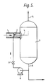
- an enlarged volume or disentrainment vessel 6 is coupled to the end of the conduit 4 emerging through the wall of the pipe 1.
- any liquid passing along the conduit 4 will be separated from the gas released by cavitation at the constriction 2.
- An ejector 7 driven by compressed gas may be required to maintain a depression within the vessel 6. Gas is drawn off at the top of the vessel and through the ejector. Degassed liquid is recovered at the bottom of the vessel. The degassed liquid can be returned to the pipe 1.
- the degassed liquid from the disentrainment vessel provides the control flow to the tangential parts of the vortex valve.
- a pump 8 and an adjustable valve 9 can be included in the flow line of the control flow.
- the flow along the pipe 1 can be a liquid or a slurry.
- the flow can be "mud" as used in the oil and gas industries for drilling.
Landscapes
- Chemical & Material Sciences (AREA)
- Chemical Kinetics & Catalysis (AREA)
- Degasification And Air Bubble Elimination (AREA)
- Structures Of Non-Positive Displacement Pumps (AREA)
Applications Claiming Priority (2)
| Application Number | Priority Date | Filing Date | Title |
|---|---|---|---|
| GB8921566 | 1989-09-23 | ||
| GB898921566A GB8921566D0 (en) | 1989-09-23 | 1989-09-23 | Degassing apparatus |
Publications (2)
| Publication Number | Publication Date |
|---|---|
| EP0420503A2 true EP0420503A2 (de) | 1991-04-03 |
| EP0420503A3 EP0420503A3 (en) | 1991-10-23 |
Family
ID=10663561
Family Applications (1)
| Application Number | Title | Priority Date | Filing Date |
|---|---|---|---|
| EP19900310308 Withdrawn EP0420503A3 (en) | 1989-09-23 | 1990-09-20 | Fluid degassing |
Country Status (7)
| Country | Link |
|---|---|
| US (1) | US5064449A (de) |
| EP (1) | EP0420503A3 (de) |
| JP (1) | JPH03118803A (de) |
| AU (1) | AU631248B2 (de) |
| CA (1) | CA2025709A1 (de) |
| GB (2) | GB8921566D0 (de) |
| NO (1) | NO904096L (de) |
Cited By (4)
| Publication number | Priority date | Publication date | Assignee | Title |
|---|---|---|---|---|
| GB2382787A (en) * | 2001-12-04 | 2003-06-11 | Thomas Tsoi-Hei Ma | A cavitation fuel separator |
| WO2003029739A3 (en) * | 2001-09-28 | 2003-08-28 | Shell Int Research | Cyclonic fluid separator with vortex generator in inlet section |
| WO2012161721A1 (en) * | 2011-05-24 | 2012-11-29 | Parker-Hannifin Corporation | Hydraulic system de-aeration device |
| US9283502B2 (en) | 2011-08-31 | 2016-03-15 | Orbital Atk, Inc. | Inertial extraction system |
Families Citing this family (11)
| Publication number | Priority date | Publication date | Assignee | Title |
|---|---|---|---|---|
| DE19650407A1 (de) * | 1996-12-05 | 1998-06-10 | Kevin Business Corp | Blut-Gas-Trennverfahren und -Trennvorrichtung |
| GB9701797D0 (en) * | 1997-01-29 | 1997-03-19 | Univ Coventry | Cavitation inducer |
| US6730214B2 (en) * | 2001-10-26 | 2004-05-04 | Angelo L. Mazzei | System and apparatus for accelerating mass transfer of a gas into a liquid |
| TW200702035A (en) | 2005-03-07 | 2007-01-16 | Univ Okayama Nat Univ Corp | Deaerator and deaerating method |
| JP4159574B2 (ja) * | 2005-06-21 | 2008-10-01 | 株式会社カイジョー | 脱気装置およびこれを用いた超音波洗浄装置 |
| CN1895719B (zh) * | 2005-06-21 | 2012-06-27 | 株式会社海上 | 脱气装置以及使用其的超声波清洗装置 |
| JP5216996B2 (ja) | 2006-02-15 | 2013-06-19 | 国立大学法人 岡山大学 | 脱気・溶解装置 |
| MX2017011742A (es) | 2015-03-24 | 2017-11-13 | Arisdyne Systems Inc | Aparato y metodo para la desgasificacion de liquidos. |
| JP7198770B2 (ja) * | 2017-04-21 | 2023-01-04 | ニューサウス イノベーションズ ピーティーワイ リミテッド | キャビテーションの防止 |
| US20210255098A1 (en) * | 2018-04-23 | 2021-08-19 | Insight Analytical Solutions Inc. | System and method for improving precision in optical measurements |
| US10712248B2 (en) * | 2018-09-27 | 2020-07-14 | Kuwait University | Apparatus for measuring disentrainment rate of air |
Family Cites Families (9)
| Publication number | Priority date | Publication date | Assignee | Title |
|---|---|---|---|---|
| US3358425A (en) * | 1966-06-14 | 1967-12-19 | Sr Gerald E Burnham | Degassing apparatus |
| US3529405A (en) * | 1968-07-09 | 1970-09-22 | Ashbrook Clifford L | Separator |
| US3778969A (en) * | 1972-04-12 | 1973-12-18 | Chicago Bridge & Iron Co | Ejector vapor recovery system for stored volatile liquids |
| US3973930A (en) * | 1973-10-09 | 1976-08-10 | Burgess Harry L | Drilling mud degasser apparatus and method |
| US4345920A (en) * | 1976-05-17 | 1982-08-24 | Borg-Warner Corporation | Vacuum deaerator |
| DE2723111C2 (de) * | 1977-05-23 | 1984-05-03 | Hartmann & Braun Ag, 6000 Frankfurt | Vorrichtung zur Entgasung eines Flüssigkeitsstromes |
| JPS5836606A (ja) * | 1981-08-26 | 1983-03-03 | Ishikawajima Harima Heavy Ind Co Ltd | 流体中の気泡集合方法 |
| EP0089186B1 (de) * | 1982-03-16 | 1985-10-30 | United Kingdom Atomic Energy Authority | Strömungsmittelbetriebenes Steuerelement |
| DE3428534A1 (de) * | 1984-08-02 | 1986-02-13 | Siekmann, Helmut E., Prof.Dr.-Ing., 1000 Berlin | Verfahren und vorrichtung zur trennung von fluiden mit unterschiedlichen dampfdruecken |
-
1989
- 1989-09-23 GB GB898921566A patent/GB8921566D0/en active Pending
-
1990
- 1990-09-19 CA CA002025709A patent/CA2025709A1/en not_active Abandoned
- 1990-09-20 NO NO90904096A patent/NO904096L/no unknown
- 1990-09-20 EP EP19900310308 patent/EP0420503A3/en not_active Withdrawn
- 1990-09-20 AU AU63055/90A patent/AU631248B2/en not_active Ceased
- 1990-09-21 JP JP2253996A patent/JPH03118803A/ja active Pending
- 1990-09-21 GB GB9020804A patent/GB2236060B/en not_active Expired - Fee Related
- 1990-09-21 US US07/586,408 patent/US5064449A/en not_active Expired - Fee Related
Cited By (10)
| Publication number | Priority date | Publication date | Assignee | Title |
|---|---|---|---|---|
| WO2003029739A3 (en) * | 2001-09-28 | 2003-08-28 | Shell Int Research | Cyclonic fluid separator with vortex generator in inlet section |
| EA005482B1 (ru) * | 2001-09-28 | 2005-02-24 | Шелл Интернэшнл Рисерч Маатсхаппий Б.В. | Циклонный сепаратор текучей среды с вихрегенератором во впускной секции |
| AU2002338824B2 (en) * | 2001-09-28 | 2007-09-13 | Twister B.V. | Cyclonic fluid separator with vortex generator in inlet section |
| AU2002338824B9 (en) * | 2001-09-28 | 2008-03-20 | Twister B.V. | Cyclonic fluid separator with vortex generator in inlet section |
| US7357825B2 (en) | 2001-09-28 | 2008-04-15 | Shell Oil Company | Cyclonic fluid separator with vortex generator in inlet section |
| CN100385190C (zh) * | 2001-09-28 | 2008-04-30 | 国际壳牌研究有限公司 | 入口段内具有涡流发生器的旋风流体分离器 |
| GB2382787A (en) * | 2001-12-04 | 2003-06-11 | Thomas Tsoi-Hei Ma | A cavitation fuel separator |
| WO2012161721A1 (en) * | 2011-05-24 | 2012-11-29 | Parker-Hannifin Corporation | Hydraulic system de-aeration device |
| US9212672B2 (en) | 2011-05-24 | 2015-12-15 | Parker-Hannifin Corporation | Hydraulic system de-aeration device |
| US9283502B2 (en) | 2011-08-31 | 2016-03-15 | Orbital Atk, Inc. | Inertial extraction system |
Also Published As
| Publication number | Publication date |
|---|---|
| GB8921566D0 (en) | 1989-11-08 |
| US5064449A (en) | 1991-11-12 |
| AU631248B2 (en) | 1992-11-19 |
| NO904096L (no) | 1991-03-25 |
| GB9020804D0 (en) | 1990-11-07 |
| NO904096D0 (no) | 1990-09-20 |
| EP0420503A3 (en) | 1991-10-23 |
| CA2025709A1 (en) | 1991-03-24 |
| GB2236060A (en) | 1991-03-27 |
| AU6305590A (en) | 1991-03-28 |
| GB2236060B (en) | 1993-08-18 |
| JPH03118803A (ja) | 1991-05-21 |
Similar Documents
| Publication | Publication Date | Title |
|---|---|---|
| US5064449A (en) | Fluid degassing | |
| EP0305163B1 (de) | Verfahren zur Strömungsregelung | |
| US5456837A (en) | Multiple cyclone apparatus for downhole cyclone oil/water separation | |
| CA2667620A1 (en) | Liquid treatment apparatus and methods | |
| CA1329148C (en) | Suction system gas separator from fluid | |
| EP0715871A2 (de) | Verfahren und Vorrichtung zur Entfernung von Blasen aus einer Flüssigkeit | |
| EP0530967B1 (de) | Durchfluss-Regelsystem | |
| GB2384027A (en) | Removing gas from low pressure wells | |
| CA1087110A (en) | Apparatus for removing gas from a liquid system | |
| US4662908A (en) | Device for removing bubbles from liquid | |
| WO1999054630A1 (en) | Pump-ejector compressor apparatus and variants | |
| CA1314819C (en) | Dynamic filter apparatus and method | |
| US5091082A (en) | Apparatus for diverting fluid-entrained solids around a centrifugal pump | |
| EP0830494B1 (de) | Verfahren zum zykloneabscheiden im bohrloch | |
| US4740317A (en) | Pump filter apparatus and method | |
| SU866298A1 (ru) | Насосна установка | |
| JPH034907A (ja) | 液体中の気泡除去システム | |
| GB2254659A (en) | Jet pump with annular nozzle and central plug | |
| RU1779796C (ru) | Насосна установка дл перекачивани газожидкостной смеси | |
| JP2000093710A (ja) | 濾過装置 | |
| SU1139512A1 (ru) | Способ управлени разделительным процессом в гидроциклоне | |
| RU1789759C (ru) | Насосна установка | |
| SU912252A1 (ru) | Эмульгатор | |
| SU918541A1 (ru) | Скважинна гидроциклонна насосна установка | |
| SU1765535A1 (ru) | Гидровихревой сепаратор центробежного насоса |
Legal Events
| Date | Code | Title | Description |
|---|---|---|---|
| PUAI | Public reference made under article 153(3) epc to a published international application that has entered the european phase |
Free format text: ORIGINAL CODE: 0009012 |
|
| AK | Designated contracting states |
Kind code of ref document: A2 Designated state(s): BE CH DE DK ES FR GR IT LI NL SE |
|
| PUAL | Search report despatched |
Free format text: ORIGINAL CODE: 0009013 |
|
| AK | Designated contracting states |
Kind code of ref document: A3 Designated state(s): BE CH DE DK ES FR GR IT LI NL SE |
|
| 17P | Request for examination filed |
Effective date: 19920312 |
|
| RAP1 | Party data changed (applicant data changed or rights of an application transferred) |
Owner name: UNITED KINGDOM ATOMIC ENERGY AUTHORITY |
|
| 17Q | First examination report despatched |
Effective date: 19930415 |
|
| STAA | Information on the status of an ep patent application or granted ep patent |
Free format text: STATUS: THE APPLICATION IS DEEMED TO BE WITHDRAWN |
|
| 18D | Application deemed to be withdrawn |
Effective date: 19940705 |