EP0420505B1 - Verfahren zur Abstimmung und zum Ausgleich von Leistungspegeln in einem Funktelefon - Google Patents
Verfahren zur Abstimmung und zum Ausgleich von Leistungspegeln in einem Funktelefon Download PDFInfo
- Publication number
- EP0420505B1 EP0420505B1 EP90310312A EP90310312A EP0420505B1 EP 0420505 B1 EP0420505 B1 EP 0420505B1 EP 90310312 A EP90310312 A EP 90310312A EP 90310312 A EP90310312 A EP 90310312A EP 0420505 B1 EP0420505 B1 EP 0420505B1
- Authority
- EP
- European Patent Office
- Prior art keywords
- radio telephone
- adjustment
- logic section
- power level
- interface
- Prior art date
- Legal status (The legal status is an assumption and is not a legal conclusion. Google has not performed a legal analysis and makes no representation as to the accuracy of the status listed.)
- Expired - Lifetime
Links
Images
Classifications
-
- H—ELECTRICITY
- H03—ELECTRONIC CIRCUITRY
- H03J—TUNING RESONANT CIRCUITS; SELECTING RESONANT CIRCUITS
- H03J3/00—Continuous tuning
- H03J3/02—Details
- H03J3/04—Arrangements for compensating for variations of physical values, e.g. temperature
-
- H—ELECTRICITY
- H04—ELECTRIC COMMUNICATION TECHNIQUE
- H04B—TRANSMISSION
- H04B17/00—Monitoring; Testing
- H04B17/10—Monitoring; Testing of transmitters
- H04B17/11—Monitoring; Testing of transmitters for calibration
- H04B17/13—Monitoring; Testing of transmitters for calibration of power amplifiers, e.g. gain or non-linearity
-
- H—ELECTRICITY
- H04—ELECTRIC COMMUNICATION TECHNIQUE
- H04B—TRANSMISSION
- H04B17/00—Monitoring; Testing
- H04B17/20—Monitoring; Testing of receivers
- H04B17/21—Monitoring; Testing of receivers for calibration; for correcting measurements
Definitions
- the invention relates to a method of adjusting and compensating power levels in a radio telephone having a logic section which controls the operation, and to the use of this method in series production and maintenance.
- the invention also relates to an adjustment system for a radio telephone, which is adjusted with a method according to the invention.
- the power levels in a radio telephone are adjusted by adjusting built-in trimmer potentiometers and monitoring the output power of the radio telephone.
- the adjustment is generally made manually, although in some cases adjustment with the aid of robots could be possible. It is however common to these prior art methods to adjust electromechanical components, such as trimmer potentiometers, with the aid of tools.
- the power of the transmitter may vary with the operating conditions of the radio telephone.
- the operating conditions are influenced by the selected channel frequency, the radio telephone's internal temperature and the supply voltage (accumulator or battery voltage).
- the supply voltage accumulate or battery voltage
- Diodes or NTC resistors are used to compensate for power variations due to temperature changes, for example.
- the transmitter output power of individual radio telephone units can behave in very different ways at various temperatures and with various voltages, and thus the compensating circuitry designed for a radio telephone type does not necessarily function in a desired manner for every unit in series production.
- the known methods entail many problems and drawbacks.
- the trimmer potentiometers being electromechanical components, are less reliable than the electronic components used in the radio telephone and they take up a substantial area on the device's circuit board.
- the need for a large space is a problem, particularly concerning handsets.
- adjustment of the trimmers is slow and requires a skilled person performing adjustment. Adjustment precision depends on the person, and thus human errors are possible.
- the radio telephone casing has to be opened for adjustment in order to get access to the various components.
- the power levels are usually compensated for temperature and battery voltage variations by analog techniques, so that the accuracy of the compensation depends on component tolerances, and a fully individual compensation will not be possible in series production.
- the object of the invention is to devise a method, with which the above mentioned prior art problems and drawbacks are obviated.
- the radio telephone's memory it is essential to store individual adjustment results for chosen operating conditions into the radio telephone's memory as compensating values, whereby the transmitter's respective power level is controlled in accordance to the adjustment results by the logic section via a D/A-converter when the radio telephone is in operation.
- the adjustment is made by connecting the adjusting equipment to the normal external connections of the radio telephone, the adjustment being made without opening the radio telephone casing.
- This adjustment arrangement may be applied to the final testing in series production of radio telephones, and to the maintenance of radio telephones.
- the adjustment system as set out in Claim 6 of set A and in Claim 5 of set B, according to the invention comprises a radio telephone which includes sensors connected to the logic section and detecting the radio telephone's operating conditions, and between the logic section and the transmitter a D/A-converter is arranged, which converts data corrected with compensating constants and output by the logic section into a voltage controlling the transmitter power.
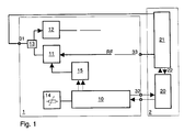
- the adjusting equipment 2 is connected to the radio telephone's 1 antenna interface 31 and auxiliary equipment interface 32 including the low frequency interface 33.
- the test signal selected for the adjustment (e.g. a constant microphone voltage or sound pressure to the microphone) is connected from the measuring device 21 of the adjusting equipment 2 to the low frequency interface 33 of the radio telephone.
- the measuring computer 20 of the adjusting equipment is connected to the logic section 10 through the auxiliary interface 32.
- the measuring computer 20 can via the logic section 10 control the radio telephone to select a desired channel (radio frequency). Through the logic section 10 it can also control the A/D-converter 15, whose output voltage is used to control the output power of the transmitter 11.
- the transmitter output power is connected to the antenna interface 31, e.g. through a duplex filter 13, and it will be measured with measuring devices 21 (i.a. a power level meter), the measuring results of which are transmitted on an internal bus 22 to the measuring computer 20.
- the radio telephone receiver 12 is also connected to the antenna interface 31.
- the radio telephone also includes a temperature sensor 14 to detect the internal temperature of the radio telephone.
- the logic section 10 i.a. also includes a microprocessor, memories -especially a non-volatile memory to store programs and compensating data - and an A/D-converter, with which the operating temperature of the batteries or accumulators and the voltage from the temperature sensor 14 is converted into a digital format which can be used by the microprocessor.
- the microprocessor is connected to the measuring computer 20 via the auxiliary equipment interface 32, through which information is transferred in both directions, e.g. information about the temperature measured by the sensor 14 to the measuring computer and set values from the measuring computer to the microprocessor.
- the operating channel (or channel range), the temperature (or temperature range) measured with the sensor 14, and the operating voltage (or the operating voltage range) measured with the D/A-converter, constitute the operating conditions of the radio telephone.
- the adjustment of the radio telephone according to the invention is carried out in the following manner.
- the adjustment is initially made at room temperature, on the middle channel and with nominal operating voltage.
- the radio telephone is placed in a climate chamber (cold/hot chamber), and the measuring devices 21 are connected to the antenna interface 31 and the low frequency interface 33.
- the adjustment may also be carried out with operating conditions in an order differing from the above order, depending on the available climate chamber arrangement and other productions reasons.
- the number of operating conditions to be adjusted may be chosen to suit the production and the operation of the radio telephone.
- the number of the operating conditions can be reduced in a convenient way by using e.g. only one adjustment point representing a middle range, a higher range and a lower range, respectively, for each variable (channel, temperature, operating voltage).
- the ranges could be:
- the adjustment can be made in the final testing, when the radio telephone is otherwise completely ready.
- the adjustment can now be made without opening the telephone's casing.
- the adjustment can be made completely automatically, whereby the results of the adjustment will become more reliable (no human errors), and individually for each radio telephone. Due to the automation the testing throughput time and the amount of required personnel will be reduced. From a production management standpoint the inventive method signifies a great advantage, when for example the production is transferred to another plant, because the automatic adjustment program does not require much training of personnel for the adjustment tasks, as all information required in the adjustment can be incorporated in the adjustment programs of the measuring computer.
- the adjustment method according to the invention can also conveniently be used in the maintenance of radio telephones, whereby the adjusting equipment may be replaced by simpler service equipment, with which e.g. the adjustment of the radio telephone is checked, and/or adjustment is made only at room temperature.
- the range of the operating conditions is measured during operation with a sensor 14 and A/D-converters (not shown).
- the microprocessor 10 selects from its non-volatile memory a compensating constant or value adjusted for the respective operating conditions, and the transmitter power level is set according to this value.
- the invention can be applied to different types of analog and digital radio telephones, cellular radio telephones, portable and mobile radio telephones.
Landscapes
- Physics & Mathematics (AREA)
- Electromagnetism (AREA)
- Engineering & Computer Science (AREA)
- Computer Networks & Wireless Communication (AREA)
- Signal Processing (AREA)
- Nonlinear Science (AREA)
- Circuits Of Receivers In General (AREA)
- Input Circuits Of Receivers And Coupling Of Receivers And Audio Equipment (AREA)
- Transceivers (AREA)
- Transmitters (AREA)
- Developing Agents For Electrophotography (AREA)
- Nitrogen Condensed Heterocyclic Rings (AREA)
Claims (9)
- Verfahren zur Einstellung eines Funktelefons, das einen seinen Betrieb steuernden Logikteil (10) enthält. dadurch gekennzeichnet, daß- eine externe Einstelleinrichtung (2) an den Antennenanschluß (31) und an einen Zusatzanschluß (32) oder entsprechende Anschlüsse des Funktelefons (1) angeschlossen wird,- ein Testsignal von einer Meßvorrichtung (21) der Einstelleinrichtung (2) an einen Niederfrequenzanschluß (33) des Funktelefons angelegt wird.- der am Antennenanschluß (31) anliegende Leistungspegel eines Senders (11) des Funktelefons von der Meßvorrichtung (21) der Einstelleinrichtung (2) gemessen und die Einstellung des Leistungspegels mittels einer den Logikteil (10) enthaltenen Rückkopplungsschleife (32, 1, 31, 2) durchgeführt wird, bis der gewünschte Leistungspegel erreicht wird.- die einzelnen Ergebnisse der Einstellung des Funktelefons (1) als Kompensationswerte in einem nichtflüchtigen Speicher des Logikteils (10) gespeichert werden, wobei- der jeweilige Leistungspegel des Senders (11) mittels eines D/A Wandlers (15) in Übereinstimmung mit den im Logikteil (10) gespeicherten Ergebnissen der Einstellung geregelt wird, wenn sich das Funktelefon (1) im Betriebszustand befindet.
- Verfahren nach Anspruch 1, dadurch gekennzeichnet, daß die Einstellung durchgeführt wird, ohne das Gehäuse des Funktelefons (1) zu öffnen.
- Verfahren nach Anspruch 1 oder 2, dadurch gekennzeichnet, daß die Einstelleinrichtung (2) ein Meßgerät (21) zum Messen eines Leistungspegels an einem Antennenanschluß (31) und einen Computer (20) mit einem gespeicherten Programm und gespeicherten Referenzwerten des Leistungspegels enthält, auf deren Grundlage die Einstellung wahlweise automatisch oder halbautomatisch durchgeführt wird.
- Verfahren nach einem der vorhergehenden Ansprüche, dadurch gekennzeichnet, daß die Einstellung sequentiell für mehrere ausgewählte Betriebsbedingungen des Funktelefons oder für mehrere Kanäle oder Kanalbereiche und für einen oder mehrere Betriebstemperaturbereiche durchgeführt wird, wobei die Einstelleinrichtung (2) Information über die Betriebsbedingungen des Funktelefons (1), die von Sensoren (14) detektiert wurden, über den Anschluß für Zusatzgeräte (32) erhält, und wobei jedes Einstellergebnis als Kompensationswert im nichtflüchtigen Speicher des Logikteils (10) des Funktelefons gespeichert wird.
- Verfahren zur Einstellung eines Funklelefons nach Anspruch 3 oder 4 bei einer Serienfertigung, dadurch gekennzeichnet, daß der Computer (20) bei der Einstellung eines Funktelefons einer Serie die Langzeit Mittelwerte des Satzes von Kompensationswerten der vorher abgestimmten Funktelefone als ersten Satz von Kompensationswerten in den Logikteil (10) des Funktelefons eingibt.
- Vorrichtung zur Einstellung eines Funktelefons, mit einem Funktelefon und einer externen Einstelleinrichtung, wobei das Funktelefon einen Antennenanschluß (31); einen Niederfrequenzanschluß (33) und Zusatzanschlüsse (32) oder entsprechende Anschlüsse; einen Logikteil (10), der den Betrieb des Funktelefons steuert und einen nichtflüchtigen Speicher enthält; an den Logikteil (10) angeschlossene Sensoren (14) zum Detektieren der Betriebsbedingungen des Funktelefons; einen Sender (11), der Leistung an denAntennenanschluß (31) liefert; und einen den Leistungspegel des Senders (11) regelnden D/A Wandler (15) aufweist, der zwischen dem Logikteil (10) und dem Sender (11) angeordnet ist, wobei der Wandler (15) so aufgebaut und angeordnet ist, daß mit einem Kompensationswert korrigierte und vom Logikteil (10) ausgegebene Daten in eine die Leistung des Senders (11) regelnde Spannung gewandelt werden, und wobei die externe Einstelleinrichtung an den Antennenanschluß und den Zusatzanschluß oder entsprechende Anschlüsse des Funktelefons angeschlossen ist und folgendes enthält:- eine Vorrichtung (21) zum Anlegen eines Testsignals über den Niederfrequenzanschluß des Funktelefons an das Funktelefon und zum Messen eines Ausgangssignals des Antennensensors, das durch das angelegte Testsignal erzeugt wurde, und- einen Meßcomputer (20) zur Einstellung des Ausgangssignals des Funktelefons mittels einer Rückkopplungsschleife über den Logikteil, bis ein gewünschter Leistungspegel des Ausgangssignals erreicht ist.
- Funktelefon nach Anspruch 6, dadurch gekennzeichnet, daß der Logikteil (10) des Funktelefons einen Mikroprozessor enthält.
- Funktelefon nach Anspruch 6 oder 7, dadurch gekennzeichnet, daß die Sensoren (10, 14) des Funktelefons. die die Betriebsbedingungen detektieren, eine Vorrichtung (10) zum Detektieren des Betriebskanals oder Kanalbereichs und/oder einen Temperatursensor (14) und/oder einen Versorgungsspannungssensor (10) aufweisen.
- Funktelefon nach einem der Ansprüche 6 bis 8, dadurch gekennzeichnet, daß es keine Einstellpotentiometer oder entsprechende elektromechanisch arbeitenden Komponenten zur Einstellung und/oder Kompensation des Leistungspegels enthält.
Applications Claiming Priority (2)
| Application Number | Priority Date | Filing Date | Title |
|---|---|---|---|
| FI894529 | 1989-09-25 | ||
| FI894529A FI83717C (fi) | 1989-09-25 | 1989-09-25 | Foerfarande foer intrimning och kompensation av effektnivaoer i en radiotelefon. |
Publications (3)
| Publication Number | Publication Date |
|---|---|
| EP0420505A2 EP0420505A2 (de) | 1991-04-03 |
| EP0420505A3 EP0420505A3 (en) | 1992-04-29 |
| EP0420505B1 true EP0420505B1 (de) | 1996-11-27 |
Family
ID=8529049
Family Applications (1)
| Application Number | Title | Priority Date | Filing Date |
|---|---|---|---|
| EP90310312A Expired - Lifetime EP0420505B1 (de) | 1989-09-25 | 1990-09-20 | Verfahren zur Abstimmung und zum Ausgleich von Leistungspegeln in einem Funktelefon |
Country Status (5)
| Country | Link |
|---|---|
| US (1) | US5230091A (de) |
| EP (1) | EP0420505B1 (de) |
| AT (1) | ATE145773T1 (de) |
| DE (1) | DE69029243T2 (de) |
| FI (1) | FI83717C (de) |
Families Citing this family (50)
| Publication number | Priority date | Publication date | Assignee | Title |
|---|---|---|---|---|
| FI83715C (fi) * | 1989-09-25 | 1991-08-12 | Nokia Mobile Phones Ltd | Logikstyrd intrimning och kompensation av signalnivaoer och deviationer i en radiotelefon. |
| HUT69370A (en) * | 1992-05-08 | 1995-09-28 | Motorola Inc | Arrangement for selective tuning of a radio receiver |
| US5711001A (en) * | 1992-05-08 | 1998-01-20 | Motorola, Inc. | Method and circuit for acquisition by a radio receiver |
| US5438699A (en) * | 1992-06-09 | 1995-08-01 | Coveley; Michael | Adaptive system for self-tuning a receiver in an RF communication system |
| GB2281461A (en) * | 1993-08-27 | 1995-03-01 | Nokia Telecommunications Oy | Control of output power in radio transmitters using look-up table |
| FI100152B (fi) * | 1993-11-22 | 1997-09-30 | Nokia Telecommunications Oy | Menetelmä lähetystehon säätämiseksi sekä tukiasemalaitteisto |
| FI101505B1 (fi) * | 1995-05-10 | 1998-06-30 | Nokia Mobile Phones Ltd | Menetelmä suuntakytkimellä toteutetun tehonmittauksen parantamiseksi pienillä tehotasoilla |
| US5752172A (en) * | 1996-08-16 | 1998-05-12 | Nokia Mobile Phones Limited | Distributed transmitter output power control circuit and method for a radio telephone |
| FI963389A7 (fi) * | 1996-08-30 | 1998-03-01 | Nokia Corp | Käsipuhelimen opastusjärjestelmä |
| FI106759B (fi) | 1996-11-13 | 2001-03-30 | Nokia Mobile Phones Ltd | Matkaviestimen lähetystehon rajoitinjärjestelmä |
| US6173160B1 (en) | 1996-11-18 | 2001-01-09 | Nokia Mobile Phones Limited | Mobile station having drift-free pulsed power detection method and apparatus |
| FI108177B (fi) | 1997-01-03 | 2001-11-30 | Nokia Mobile Phones Ltd | Matkaviestinlaitteiden lähetin |
| US5884149A (en) * | 1997-02-13 | 1999-03-16 | Nokia Mobile Phones Limited | Mobile station having dual band RF detector and gain control |
| DE19705735A1 (de) * | 1997-02-14 | 1998-08-20 | Nokia Mobile Phones Ltd | Verfahren und Vorrichtung zur Inspektion wenigstens eines Antennenzweigs, insbesondere in einem Fahrzeug |
| KR19990040843A (ko) | 1997-11-20 | 1999-06-15 | 윤종용 | 코드분할 다중접속 디지털 이동통신 시스템의 기지국 송신출력측정 및 기지국 호 시험을 위한 전력 검출 및 시험 단말장치 |
| FI105611B (fi) * | 1998-03-13 | 2000-09-15 | Nokia Mobile Phones Ltd | Radiotajuusvahvistimet |
| GB9811382D0 (en) | 1998-05-27 | 1998-07-22 | Nokia Mobile Phones Ltd | A transmitter |
| GB9811381D0 (en) | 1998-05-27 | 1998-07-22 | Nokia Mobile Phones Ltd | Predistortion control for power reduction |
| GB2339113B (en) | 1998-06-30 | 2003-05-21 | Nokia Mobile Phones Ltd | Data transmission in tdma system |
| US6418301B1 (en) * | 1999-08-04 | 2002-07-09 | Harris Corporation | Methods for radio calibration at room temperature |
| US8744384B2 (en) | 2000-07-20 | 2014-06-03 | Blackberry Limited | Tunable microwave devices with auto-adjusting matching circuit |
| US7027789B2 (en) * | 2000-09-11 | 2006-04-11 | Xytrans, Inc. | Self-tuned millimeter wave RF transceiver module |
| CN1324849C (zh) * | 2003-10-17 | 2007-07-04 | 智捷科技股份有限公司 | 无线网路产品调整输出功率的方法 |
| EP1583265B1 (de) * | 2004-04-01 | 2012-12-12 | Intel Mobile Communications GmbH | Verfahren zur Kalibrierung der Sende- und Empfängerwege eines Kommunikationsgeräts, und Testsystem dafür |
| DE102005004631A1 (de) | 2004-09-29 | 2006-04-13 | Rohde & Schwarz Gmbh & Co. Kg | Verfahren und System zur Sende- und/oder Empfangskalibrierung von Mobilfunkgeräten |
| US7647028B2 (en) * | 2005-04-06 | 2010-01-12 | Skyworks Solutions, Inc. | Internal calibration system for a radio frequency (RF) transmitter |
| US9406444B2 (en) | 2005-11-14 | 2016-08-02 | Blackberry Limited | Thin film capacitors |
| US7711337B2 (en) | 2006-01-14 | 2010-05-04 | Paratek Microwave, Inc. | Adaptive impedance matching module (AIMM) control architectures |
| US7535312B2 (en) | 2006-11-08 | 2009-05-19 | Paratek Microwave, Inc. | Adaptive impedance matching apparatus, system and method with improved dynamic range |
| US7714676B2 (en) | 2006-11-08 | 2010-05-11 | Paratek Microwave, Inc. | Adaptive impedance matching apparatus, system and method |
| US7917104B2 (en) | 2007-04-23 | 2011-03-29 | Paratek Microwave, Inc. | Techniques for improved adaptive impedance matching |
| US7991363B2 (en) | 2007-11-14 | 2011-08-02 | Paratek Microwave, Inc. | Tuning matching circuits for transmitter and receiver bands as a function of transmitter metrics |
| US8072285B2 (en) | 2008-09-24 | 2011-12-06 | Paratek Microwave, Inc. | Methods for tuning an adaptive impedance matching network with a look-up table |
| US9026062B2 (en) | 2009-10-10 | 2015-05-05 | Blackberry Limited | Method and apparatus for managing operations of a communication device |
| US8803631B2 (en) | 2010-03-22 | 2014-08-12 | Blackberry Limited | Method and apparatus for adapting a variable impedance network |
| CN102948083B (zh) | 2010-04-20 | 2015-05-27 | 黑莓有限公司 | 通信设备中管理干扰的方法和装置 |
| US9379454B2 (en) | 2010-11-08 | 2016-06-28 | Blackberry Limited | Method and apparatus for tuning antennas in a communication device |
| US8712340B2 (en) | 2011-02-18 | 2014-04-29 | Blackberry Limited | Method and apparatus for radio antenna frequency tuning |
| US8655286B2 (en) | 2011-02-25 | 2014-02-18 | Blackberry Limited | Method and apparatus for tuning a communication device |
| US8594584B2 (en) | 2011-05-16 | 2013-11-26 | Blackberry Limited | Method and apparatus for tuning a communication device |
| WO2013022826A1 (en) | 2011-08-05 | 2013-02-14 | Research In Motion Rf, Inc. | Method and apparatus for band tuning in a communication device |
| US8948889B2 (en) | 2012-06-01 | 2015-02-03 | Blackberry Limited | Methods and apparatus for tuning circuit components of a communication device |
| US9853363B2 (en) | 2012-07-06 | 2017-12-26 | Blackberry Limited | Methods and apparatus to control mutual coupling between antennas |
| US9246223B2 (en) | 2012-07-17 | 2016-01-26 | Blackberry Limited | Antenna tuning for multiband operation |
| US9350405B2 (en) | 2012-07-19 | 2016-05-24 | Blackberry Limited | Method and apparatus for antenna tuning and power consumption management in a communication device |
| US9413066B2 (en) | 2012-07-19 | 2016-08-09 | Blackberry Limited | Method and apparatus for beam forming and antenna tuning in a communication device |
| US9362891B2 (en) * | 2012-07-26 | 2016-06-07 | Blackberry Limited | Methods and apparatus for tuning a communication device |
| US9374113B2 (en) | 2012-12-21 | 2016-06-21 | Blackberry Limited | Method and apparatus for adjusting the timing of radio antenna tuning |
| US10404295B2 (en) | 2012-12-21 | 2019-09-03 | Blackberry Limited | Method and apparatus for adjusting the timing of radio antenna tuning |
| US9438319B2 (en) | 2014-12-16 | 2016-09-06 | Blackberry Limited | Method and apparatus for antenna selection |
Family Cites Families (8)
| Publication number | Priority date | Publication date | Assignee | Title |
|---|---|---|---|---|
| US4613990A (en) * | 1984-06-25 | 1986-09-23 | At&T Bell Laboratories | Radiotelephone transmission power control |
| US4870699A (en) * | 1986-03-26 | 1989-09-26 | General Electric Company | Method and apparatus for controlling the frequency of operation and at least one further variable operating parameter of a radio communications device |
| GB8826918D0 (en) * | 1988-11-17 | 1988-12-21 | Motorola Inc | Power amplifier for radio frequency signal |
| GB8830282D0 (en) * | 1988-12-28 | 1989-02-22 | Astec Int Ltd | The setting of electronic circuits |
| US4903327A (en) * | 1989-02-03 | 1990-02-20 | Motorola, Inc. | Cellular telephone with transmission-on and radio-on timers |
| US5091919A (en) * | 1989-02-08 | 1992-02-25 | Nokia-Mobira Oy | Transmitter arrangement for digitally modulated signals |
| US5034697A (en) * | 1989-06-09 | 1991-07-23 | United States Of America As Represented By The Secretary Of The Navy | Magnetic amplifier switch for automatic tuning of VLF transmitting antenna |
| FI83715C (fi) * | 1989-09-25 | 1991-08-12 | Nokia Mobile Phones Ltd | Logikstyrd intrimning och kompensation av signalnivaoer och deviationer i en radiotelefon. |
-
1989
- 1989-09-25 FI FI894529A patent/FI83717C/fi active IP Right Grant
-
1990
- 1990-09-17 US US07/583,942 patent/US5230091A/en not_active Expired - Lifetime
- 1990-09-20 AT AT90310312T patent/ATE145773T1/de not_active IP Right Cessation
- 1990-09-20 EP EP90310312A patent/EP0420505B1/de not_active Expired - Lifetime
- 1990-09-20 DE DE69029243T patent/DE69029243T2/de not_active Expired - Fee Related
Also Published As
| Publication number | Publication date |
|---|---|
| FI83717B (fi) | 1991-04-30 |
| EP0420505A2 (de) | 1991-04-03 |
| ATE145773T1 (de) | 1996-12-15 |
| FI83717C (fi) | 1991-08-12 |
| EP0420505A3 (en) | 1992-04-29 |
| FI894529A0 (fi) | 1989-09-25 |
| US5230091A (en) | 1993-07-20 |
| DE69029243D1 (de) | 1997-01-09 |
| DE69029243T2 (de) | 1997-04-24 |
Similar Documents
| Publication | Publication Date | Title |
|---|---|---|
| US5230091A (en) | Method and apparatus for tuning and compensating power levels in a radio telephone | |
| EP0420508B1 (de) | Digital gesteuerte Anpassung und Ausgleich von Signalpegeln und Abweichungen in einem Funktelefon | |
| US5335362A (en) | Method of tuning and compensating the received signal strength indicator in a radio telephone | |
| US5101173A (en) | Stored program controlled module amplifier bias and amplitude/phase compensation apparatus | |
| US4726071A (en) | Microprocessor controlled self-tuning resonant cavity and method | |
| US4418392A (en) | Measuring device | |
| EP0540908B1 (de) | Verfahren und Einrichtung zur automatischen Abstimmkalibrierung von elektronisch abgestimmten Filtern | |
| EP0376666A1 (de) | Einrichtung von elektronischen Schaltungen | |
| US4545445A (en) | Span adjusting system of electronic weighing apparatus | |
| US9148133B2 (en) | Trimming circuit, power supply including trimming circuit, and trimming method | |
| GB2313723A (en) | Controlling the output power of a mobile phone using a look-up table for attenuation values and frequencies | |
| EP0420506B1 (de) | Verfahren zur Vereinfachung der Anpassung eines Funk-Telefons | |
| US6311044B1 (en) | Method and apparatus for determining failure modes of a transceiver | |
| WO1992008299A1 (en) | A base station for a radio system | |
| US7392405B2 (en) | Digitally controlled power supply | |
| CN118337214A (zh) | 模拟量处理电路及方法 | |
| EP0446073A1 (de) | Verfahren zur Genauigkeitsverbesserung von Leistungsregelung in einem Funktelefon | |
| WO1995015037A1 (en) | A method for adjusting transmission power, and a base station | |
| RU2173501C2 (ru) | Способ и устройство для автоматической регулировки передаваемой мощности | |
| JP2704141B2 (ja) | 無線装置およびこの無線装置の計測調整方式 | |
| JPH11112364A (ja) | 送信回路 | |
| EP0772786A1 (de) | Radar-vorrichtung mit einer anordnung zur eichung der stabilisierung | |
| JP2668166B2 (ja) | データ伝送システムにおける端末調整装置 | |
| SU919099A1 (ru) | Корректор соединительных линий | |
| EP1160995B1 (de) | Mobiles Endgerät für drahtloses Telekommunikationssystem |
Legal Events
| Date | Code | Title | Description |
|---|---|---|---|
| PUAI | Public reference made under article 153(3) epc to a published international application that has entered the european phase |
Free format text: ORIGINAL CODE: 0009012 |
|
| AK | Designated contracting states |
Kind code of ref document: A2 Designated state(s): AT BE CH DE DK ES FR GB GR IT LI LU NL SE |
|
| PUAL | Search report despatched |
Free format text: ORIGINAL CODE: 0009013 |
|
| AK | Designated contracting states |
Kind code of ref document: A3 Designated state(s): AT BE CH DE DK ES FR GB GR IT LI LU NL SE |
|
| 17P | Request for examination filed |
Effective date: 19920904 |
|
| 17Q | First examination report despatched |
Effective date: 19940826 |
|
| GRAH | Despatch of communication of intention to grant a patent |
Free format text: ORIGINAL CODE: EPIDOS IGRA |
|
| GRAH | Despatch of communication of intention to grant a patent |
Free format text: ORIGINAL CODE: EPIDOS IGRA |
|
| GRAA | (expected) grant |
Free format text: ORIGINAL CODE: 0009210 |
|
| AK | Designated contracting states |
Kind code of ref document: B1 Designated state(s): AT BE CH DE DK ES FR GB GR IT LI LU NL SE |
|
| PG25 | Lapsed in a contracting state [announced via postgrant information from national office to epo] |
Ref country code: AT Effective date: 19961127 Ref country code: DK Effective date: 19961127 Ref country code: BE Effective date: 19961127 Ref country code: CH Effective date: 19961127 Ref country code: GR Free format text: LAPSE BECAUSE OF FAILURE TO SUBMIT A TRANSLATION OF THE DESCRIPTION OR TO PAY THE FEE WITHIN THE PRESCRIBED TIME-LIMIT Effective date: 19961127 Ref country code: ES Free format text: THE PATENT HAS BEEN ANNULLED BY A DECISION OF A NATIONAL AUTHORITY Effective date: 19961127 Ref country code: LI Effective date: 19961127 Ref country code: NL Free format text: LAPSE BECAUSE OF FAILURE TO SUBMIT A TRANSLATION OF THE DESCRIPTION OR TO PAY THE FEE WITHIN THE PRESCRIBED TIME-LIMIT Effective date: 19961127 |
|
| REF | Corresponds to: |
Ref document number: 145773 Country of ref document: AT Date of ref document: 19961215 Kind code of ref document: T |
|
| ET | Fr: translation filed | ||
| REF | Corresponds to: |
Ref document number: 69029243 Country of ref document: DE Date of ref document: 19970109 |
|
| ITF | It: translation for a ep patent filed | ||
| NLV1 | Nl: lapsed or annulled due to failure to fulfill the requirements of art. 29p and 29m of the patents act | ||
| REG | Reference to a national code |
Ref country code: CH Ref legal event code: PL |
|
| PG25 | Lapsed in a contracting state [announced via postgrant information from national office to epo] |
Ref country code: LU Free format text: LAPSE BECAUSE OF NON-PAYMENT OF DUE FEES Effective date: 19970930 |
|
| PLBE | No opposition filed within time limit |
Free format text: ORIGINAL CODE: 0009261 |
|
| STAA | Information on the status of an ep patent application or granted ep patent |
Free format text: STATUS: NO OPPOSITION FILED WITHIN TIME LIMIT |
|
| 26N | No opposition filed | ||
| REG | Reference to a national code |
Ref country code: GB Ref legal event code: IF02 |
|
| REG | Reference to a national code |
Ref country code: GB Ref legal event code: 732E |
|
| PGFP | Annual fee paid to national office [announced via postgrant information from national office to epo] |
Ref country code: SE Payment date: 20020904 Year of fee payment: 13 |
|
| PG25 | Lapsed in a contracting state [announced via postgrant information from national office to epo] |
Ref country code: SE Free format text: LAPSE BECAUSE OF NON-PAYMENT OF DUE FEES Effective date: 20030921 |
|
| EUG | Se: european patent has lapsed | ||
| PGFP | Annual fee paid to national office [announced via postgrant information from national office to epo] |
Ref country code: FR Payment date: 20050823 Year of fee payment: 16 |
|
| PGFP | Annual fee paid to national office [announced via postgrant information from national office to epo] |
Ref country code: GB Payment date: 20050914 Year of fee payment: 16 |
|
| PGFP | Annual fee paid to national office [announced via postgrant information from national office to epo] |
Ref country code: DE Payment date: 20050915 Year of fee payment: 16 |
|
| PG25 | Lapsed in a contracting state [announced via postgrant information from national office to epo] |
Ref country code: IT Free format text: LAPSE BECAUSE OF NON-PAYMENT OF DUE FEES Effective date: 20050920 |
|
| PG25 | Lapsed in a contracting state [announced via postgrant information from national office to epo] |
Ref country code: DE Free format text: LAPSE BECAUSE OF NON-PAYMENT OF DUE FEES Effective date: 20070403 |
|
| GBPC | Gb: european patent ceased through non-payment of renewal fee |
Effective date: 20060920 |
|
| REG | Reference to a national code |
Ref country code: FR Ref legal event code: ST Effective date: 20070531 |
|
| PG25 | Lapsed in a contracting state [announced via postgrant information from national office to epo] |
Ref country code: GB Free format text: LAPSE BECAUSE OF NON-PAYMENT OF DUE FEES Effective date: 20060920 |
|
| PG25 | Lapsed in a contracting state [announced via postgrant information from national office to epo] |
Ref country code: FR Free format text: LAPSE BECAUSE OF NON-PAYMENT OF DUE FEES Effective date: 20061002 |