EP0420799A2 - Elément de fixation pour panneaux d'isolation - Google Patents
Elément de fixation pour panneaux d'isolation Download PDFInfo
- Publication number
- EP0420799A2 EP0420799A2 EP90810693A EP90810693A EP0420799A2 EP 0420799 A2 EP0420799 A2 EP 0420799A2 EP 90810693 A EP90810693 A EP 90810693A EP 90810693 A EP90810693 A EP 90810693A EP 0420799 A2 EP0420799 A2 EP 0420799A2
- Authority
- EP
- European Patent Office
- Prior art keywords
- hollow shaft
- fastening element
- nail
- sleeve
- abutment
- Prior art date
- Legal status (The legal status is an assumption and is not a legal conclusion. Google has not performed a legal analysis and makes no representation as to the accuracy of the status listed.)
- Granted
Links
Images
Classifications
-
- E—FIXED CONSTRUCTIONS
- E04—BUILDING
- E04B—GENERAL BUILDING CONSTRUCTIONS; WALLS, e.g. PARTITIONS; ROOFS; FLOORS; CEILINGS; INSULATION OR OTHER PROTECTION OF BUILDINGS
- E04B1/00—Constructions in general; Structures which are not restricted either to walls, e.g. partitions, or floors or ceilings or roofs
- E04B1/62—Insulation or other protection; Elements or use of specified material therefor
- E04B1/74—Heat, sound or noise insulation, absorption, or reflection; Other building methods affording favourable thermal or acoustical conditions, e.g. accumulating of heat within walls
- E04B1/76—Heat, sound or noise insulation, absorption, or reflection; Other building methods affording favourable thermal or acoustical conditions, e.g. accumulating of heat within walls specifically with respect to heat only
- E04B1/762—Exterior insulation of exterior walls
- E04B1/7629—Details of the mechanical connection of the insulation to the wall
- E04B1/7633—Dowels with enlarged insulation retaining head
-
- E—FIXED CONSTRUCTIONS
- E04—BUILDING
- E04D—ROOF COVERINGS; SKY-LIGHTS; GUTTERS; ROOF-WORKING TOOLS
- E04D3/00—Roof covering by making use of flat or curved slabs or stiff sheets
- E04D3/36—Connecting; Fastening
- E04D3/3601—Connecting; Fastening of roof covering supported by the roof structure with interposition of a insulating layer
- E04D3/3603—Connecting; Fastening of roof covering supported by the roof structure with interposition of a insulating layer the fastening means being screws or nails
-
- F—MECHANICAL ENGINEERING; LIGHTING; HEATING; WEAPONS; BLASTING
- F16—ENGINEERING ELEMENTS AND UNITS; GENERAL MEASURES FOR PRODUCING AND MAINTAINING EFFECTIVE FUNCTIONING OF MACHINES OR INSTALLATIONS; THERMAL INSULATION IN GENERAL
- F16B—DEVICES FOR FASTENING OR SECURING CONSTRUCTIONAL ELEMENTS OR MACHINE PARTS TOGETHER, e.g. NAILS, BOLTS, CIRCLIPS, CLAMPS, CLIPS OR WEDGES; JOINTS OR JOINTING
- F16B43/00—Washers or equivalent devices; Other devices for supporting bolt-heads or nuts
-
- F—MECHANICAL ENGINEERING; LIGHTING; HEATING; WEAPONS; BLASTING
- F16—ENGINEERING ELEMENTS AND UNITS; GENERAL MEASURES FOR PRODUCING AND MAINTAINING EFFECTIVE FUNCTIONING OF MACHINES OR INSTALLATIONS; THERMAL INSULATION IN GENERAL
- F16B—DEVICES FOR FASTENING OR SECURING CONSTRUCTIONAL ELEMENTS OR MACHINE PARTS TOGETHER, e.g. NAILS, BOLTS, CIRCLIPS, CLAMPS, CLIPS OR WEDGES; JOINTS OR JOINTING
- F16B19/00—Bolts without screw-thread; Pins, including deformable elements; Rivets
- F16B19/14—Bolts or the like for shooting into concrete constructions, metal walls or the like by means of detonation-operated nailing tools
Definitions
- the invention relates to a fastening element for fastening insulation plates to components, with a large-area head and a hollow shaft protruding therefrom, with a crumple zone and an abutment for a nail.
- EP-A-0 187 168 discloses an essentially mushroom-shaped fastening element for fastening insulation plates, which mostly consist of material with low compressive strength, to components, which is fixed to the component by means of a nail.
- the drive-in resistance of the nail can change due to the uneven strength of the component, for example made of concrete, which leads to different drive-in depths when the nails are driven in with a predetermined amount of energy-powered setting tools.
- a wall section is designed as a crumple zone. Depending on the driving depth of the nail, the crumple zone is compressed to a greater or lesser extent by overexertion, as a result of which the fastening element is shortened overall.
- the head of the fastening element penetrates more or less deeply into the insulation plates, whereby damage to the insulation plates on the upper side can occur in the area of the fastening points.
- immersing the head at different depths in the insulation plates leads to an uneven contour of the top of the insulation plates, which can have an optically disadvantageous effect.
- the invention has for its object to provide a fastener for attaching insulation panels to components, which ensures the retention of the mounting height of the head even with different driving depth of the nails.
- the object is achieved in that the crumple zone is arranged between the abutment and the hollow shaft.
- a nail driven, for example, by means of powder-powered setting tools runs up against the abutment, any excess energy being reduced by shortening the crumple zone, while the nail remains in contact with the abutment which has migrated in the driving direction in accordance with the shortening of the crumple zone.
- the fastening height between the head of the fastening element and the component does not change, so that regardless of the driving depth of the nail, the head of the fastening element does not enter the insulation plates.
- the crumple zone is advantageously designed as a free-standing, compressible part which projects into the hollow shaft.
- the compressible part can be arranged in a section of the hollow shaft facing away from the head of the fastening element, as a result of which short nails can be used since, in the driven-in state, they only have to protrude beyond the component over part of the length of the hollow shaft.
- the compressible part is expediently designed as a sleeve in order to ensure an evenly distributed transmission of the forces introduced by the nail via the abutment. In this way, a defined, largely continuous deformation of the crumple zone is achieved.
- the free-standing length of the sleeve corresponds, for example, to 2 to 5 times the bore diameter and the wall thickness to 0.2 to 0.5 times the bore diameter of the sleeve.
- the crumple zone is preferably connected in one piece to the hollow shaft, which has manufacturing advantages leads, especially in the injection molding of the fastening element made of plastic.
- the sleeve is fastened as a separate part, for example by means of a clamp fit in the hollow shaft. While steel is suitable as the material for the sleeve, which allows a thin wall thickness, the remaining part of the fastening element can be made of plastic. This embodiment is particularly suitable for fastening cases where hollow layers between the insulation plates and the components must be expected.
- the end of the sleeve facing away from the abutment is expediently aligned with the end of the hollow shaft facing away from the head, which means that when any hollow layers occur, the sleeve only has to be displaced towards the component to the extent of the gap provided by the hollow layer.
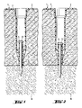
- the fastening element 1 shown in FIGS. 1 and 2 has a large-area head 2, from which a hollow shaft 3 protrudes.
- a radially compressible sleeve 4 protrudes into the hollow shaft 3, the free-standing end of which serves as an abutment 5. With the end facing away from the abutment 5, the sleeve 4 is integrally connected to the hollow shaft 3 and is thus axially supported.
- the hollow shaft 3 is tapered and provided with longitudinal ribs 6 to increase the bending rigidity.
- the fastening element 1 is used to fasten an insulation plate 7 to a component 8.
- the fastening element 1 is first pushed through the insulation plate 7 with the hollow shaft 3. Depending on the strength of the insulation plate 7, this is pre-drilled for this.
- the head 2 comes into contact with the insulation plate 7, while the free end of the hollow shaft 3 can be supported on the component 8.
- a nail 9 with a shank 11 is driven into the component 8 through the hollow shank 3 by means of a preferably powder-powered setting tool.
- a nail head 12 runs onto the abutment 5 at the end of the driving process, as a result of which the fastening element 1 and thus also the insulation plate 7 attaches to the component 8.
- the nail 9 has been driven in with excessive energy, which is the case, for example, when the component 8, due to inhomogeneity at the fastening point, opposes the nail 9 with a lower driving resistance than that at the fastening point according to FIG. 1 Case is.
- the shaft 11 being driven deeper into the component 8, the sleeve 4 is compressed into a bellows-like shape while reducing the excess energy, the nail head 12 always remaining in contact with the abutment 5.
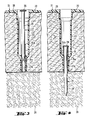
- the fastening element 21 according to FIGS. 3 and 4 in turn has a head 22 and a protruding hollow shaft 23.
- the sleeve 24 is slidably held in the central bore 23a of the end section of the hollow shaft 23 facing away from the head 22, as shown in FIG. 3.
- the sleeve 24 In the region protruding into the end section of the hollow shaft 23, the sleeve 24 has a circumferential bead 24a, which is supported radially in the central bore 23a.
- the free end of the sleeve 24 forms an abutment 24b.
- the fastening element 21 provided for fastening an insulation plate 25 to a component 26 is fixed to the component 26 by means of a nail 27.
- the fastening element 21 with the hollow shaft 23 is pushed through the possibly predrilled insulation plate 25, the head 22 resting against the top of the insulation plate 25.
- the free end of the hollow shaft 23 and the end of the region of the sleeve 24 contained in the hollow shaft 23 protrude to the underside of the insulation plate 25.
- the insulation plate 25 does not rest on the component 26 which has an uneven surface in the region of the fastening point - there is therefore a so-called hollow support which can be bridged by the sleeve 24 as follows.
- this overcomes the clamping force between the sleeve 24 and the hollow shaft 23 and takes the sleeve 24 in the driving-in direction until it runs up on the top of the component 26. Then the nail 27 moves relative to the sleeve 24 to penetrate the component 26.
- the sleeve 24 is widened by the shaft 28 of the nail 27 in the region of the bead 24a, as a result of which the latter is positively pressed into the wall of the hollow shaft 23, as shown in FIG. 4.
- the sleeve 24 is thus reliably axially fixed in the hollow shaft 23.
- the nail head 29 runs on the abutment 24b. If there is any excess energy, as shown in FIG. 4, the sleeve 24 projecting into the hollow shaft 23 can be compressed.
- the upsetting causes the free-standing sleeve 24 to increase in diameter, thereby creating an axial support for the hollow shaft 23.
Landscapes
- Engineering & Computer Science (AREA)
- Architecture (AREA)
- General Engineering & Computer Science (AREA)
- Mechanical Engineering (AREA)
- Civil Engineering (AREA)
- Structural Engineering (AREA)
- Physics & Mathematics (AREA)
- Acoustics & Sound (AREA)
- Electromagnetism (AREA)
- Joining Of Building Structures In Genera (AREA)
- Insertion Pins And Rivets (AREA)
- Connection Of Plates (AREA)
- Finishing Walls (AREA)
- Dowels (AREA)
Priority Applications (1)
| Application Number | Priority Date | Filing Date | Title |
|---|---|---|---|
| AT90810693T ATE97186T1 (de) | 1989-09-23 | 1990-09-13 | Befestigungselement zum befestigen von isolationsplatten. |
Applications Claiming Priority (2)
| Application Number | Priority Date | Filing Date | Title |
|---|---|---|---|
| DE3931833 | 1989-09-23 | ||
| DE3931833A DE3931833A1 (de) | 1989-09-23 | 1989-09-23 | Befestigungselement zum befestigen von isolationsplatten |
Publications (3)
| Publication Number | Publication Date |
|---|---|
| EP0420799A2 true EP0420799A2 (fr) | 1991-04-03 |
| EP0420799A3 EP0420799A3 (en) | 1991-11-06 |
| EP0420799B1 EP0420799B1 (fr) | 1993-11-10 |
Family
ID=6390062
Family Applications (1)
| Application Number | Title | Priority Date | Filing Date |
|---|---|---|---|
| EP90810693A Expired - Lifetime EP0420799B1 (fr) | 1989-09-23 | 1990-09-13 | Elément de fixation pour panneaux d'isolation |
Country Status (6)
| Country | Link |
|---|---|
| US (1) | US5054983A (fr) |
| EP (1) | EP0420799B1 (fr) |
| JP (1) | JP2899092B2 (fr) |
| AT (1) | ATE97186T1 (fr) |
| CA (1) | CA2025936C (fr) |
| DE (2) | DE3931833A1 (fr) |
Cited By (9)
| Publication number | Priority date | Publication date | Assignee | Title |
|---|---|---|---|---|
| EP0578923A1 (fr) * | 1992-07-17 | 1994-01-19 | EJOT KUNSTSTOFFTECHNIK GmbH & Co. KG | Broche d'assemblage |
| EP0602313A3 (fr) * | 1992-08-05 | 1994-08-03 | Itw Befestigungssysteme | |
| EP0620335A1 (fr) * | 1993-04-05 | 1994-10-19 | UPAT GMBH & CO | Elément de fixation de panneaux isolants |
| EP0636754A1 (fr) * | 1993-07-26 | 1995-02-01 | EJOT KUNSTSTOFFTECHNIK GmbH & Co. KG | Elément de fixation et outil d'enfoncement pour un tel élément de fixation |
| EP0728882A1 (fr) * | 1995-02-21 | 1996-08-28 | HILTI Aktiengesellschaft | Elément de fixation pour plaques d'épaisseur élévée sur des éléments de construction |
| EP0676551A3 (fr) * | 1994-04-09 | 1996-10-30 | Hilti Ag | Dispositif de fixation pour l'enfoncement dans des matériaux durs au moyen d'appareils de scellement à actionnement pyrotechnique. |
| WO2013045172A1 (fr) * | 2011-09-27 | 2013-04-04 | Endress+Hauser Flowtec Ag | Manchon pour vis |
| AT522756A1 (de) * | 2019-07-12 | 2021-01-15 | Austrotherm Gmbh | Platte zum Befestigen von Wärmedämmplatten |
| EP4187034A1 (fr) * | 2021-11-30 | 2023-05-31 | Hilti Aktiengesellschaft | Procédé et dispositif de fixation d'un composant à un substrat |
Families Citing this family (25)
| Publication number | Priority date | Publication date | Assignee | Title |
|---|---|---|---|---|
| DE4041819A1 (de) * | 1990-12-24 | 1992-06-25 | Hilti Ag | Befestigungselement fuer isolationsplatten |
| US5212927A (en) * | 1991-01-30 | 1993-05-25 | J. P. Sheahan Associates, Inc. | Leak localizing using a combination of penetrating devices and barriers |
| DE4135500A1 (de) * | 1991-10-28 | 1993-04-29 | Hilti Ag | Nagel mit huelse und rondelle |
| DE9206380U1 (de) * | 1992-05-12 | 1993-09-09 | Fischerwerke Artur Fischer Gmbh & Co Kg, 72178 Waldachtal | Befestigungselement für Dämmstoffplatten |
| DE4318965C2 (de) * | 1993-06-08 | 1996-04-11 | Hilti Ag | Verfahren zum Setzen von Befestigungselementen |
| DE4403717A1 (de) * | 1994-02-07 | 1995-08-10 | Hilti Ag | Befestigungselement zum Befestigen von Isolationsplatten |
| US5511918A (en) * | 1994-04-26 | 1996-04-30 | Rotter; Martin J. | Nail |
| US5607272A (en) * | 1995-01-06 | 1997-03-04 | Illinois Tool Works Inc. | Attachment plate for insulation panels |
| DE19504984A1 (de) * | 1995-02-15 | 1996-08-22 | Hilti Ag | Befestigungselement für Isolationsmaterialien |
| DE19536171A1 (de) * | 1995-09-28 | 1997-04-03 | Ejot Kunststofftech Gmbh | Befestigungselement für die Befestigung von wärmeisolierenden Materialien |
| US5704572A (en) * | 1995-10-06 | 1998-01-06 | Illinois Tool Works Inc. | Method and apparatus for fastening |
| US5626451A (en) * | 1995-10-12 | 1997-05-06 | Wind-Lock Corporation | Washer for use with exterior insulation |
| US5907938A (en) * | 1997-10-08 | 1999-06-01 | Sheahan; James P. | Anti-backout roof fasteners |
| US6171042B1 (en) | 1997-12-19 | 2001-01-09 | Illinois Tool Works Inc. | Hardened steel pin, pin and washer fastener, washer for fastener, and pin-making method |
| US6513301B1 (en) | 1999-10-20 | 2003-02-04 | Robert Snyder | Method of and instrument or arrangement for installing thermal insulation sheets in confined areas |
| FR2800813B1 (fr) * | 1999-11-10 | 2002-02-15 | Prospection & Inventions | Embase de fixation d'une piece perforee a un support |
| US8250823B2 (en) * | 2003-08-26 | 2012-08-28 | Ejot Gmbh & Co. Kg | Dowels and methods for the assembly of insulating panels |
| US20060107612A1 (en) * | 2004-10-01 | 2006-05-25 | Pelc Robert J | Anchoring device |
| DE102008041036A1 (de) * | 2008-08-06 | 2010-02-11 | Hilti Aktiengesellschaft | Nagelförmiges Befestigungselement |
| US8791375B2 (en) * | 2010-12-16 | 2014-07-29 | The Boeing Company | Electrically conductive bushing connection to structure for current path |
| US10228007B2 (en) * | 2015-12-09 | 2019-03-12 | Illinois Tool Works Inc. | Panel fastener |
| US10167885B2 (en) * | 2016-03-21 | 2019-01-01 | United Technologies Corporation | Mechanical joint with a flanged retainer |
| EP3258025A1 (fr) * | 2016-06-16 | 2017-12-20 | EJOT Baubefestigungen GmbH | Système de fixation de composants sur un support avec une couche isolante |
| US11536308B2 (en) | 2018-12-03 | 2022-12-27 | Arrowhead Design and Innovation, LLC | Adjustable fastener system |
| PL3751069T3 (pl) * | 2019-06-13 | 2022-03-07 | Rautaruukki Oyj | System mocowania do zamocowania paneli kompozytowych o strukturze warstwowej do konstrukcji podporowej |
Family Cites Families (8)
| Publication number | Priority date | Publication date | Assignee | Title |
|---|---|---|---|---|
| DE2504816A1 (de) * | 1974-02-05 | 1975-08-07 | Olin Corp | Zusammengesetztes befestigungsteil |
| US4380413A (en) * | 1980-11-03 | 1983-04-19 | Illinois Tool Works Inc. | Load-distributive washer for use with compressible material |
| US4545270A (en) * | 1981-05-07 | 1985-10-08 | Illinois Tool Works Inc. | Device for assuring predetermined joint loading in roof insulation assemblies |
| EP0187168A1 (fr) * | 1984-12-22 | 1986-07-16 | EJOT Adolf Böhl GmbH & Co. KG | Dispositif de fixation |
| DE3538271A1 (de) * | 1985-10-28 | 1987-04-30 | Niederberg Chemie | Halter fuer flachdaecher |
| US4757661A (en) * | 1986-03-17 | 1988-07-19 | Illinois Tool Works, Inc. | Washer with axial ribs |
| DE3707424A1 (de) * | 1987-03-07 | 1988-09-15 | Hilti Ag | Befestigungselement mit nagel und huelse |
| DE3743049A1 (de) * | 1987-12-18 | 1989-06-29 | Hilti Ag | Nagel mit stauchbarer huelse |
-
1989
- 1989-09-23 DE DE3931833A patent/DE3931833A1/de not_active Withdrawn
-
1990
- 1990-09-13 AT AT90810693T patent/ATE97186T1/de not_active IP Right Cessation
- 1990-09-13 DE DE90810693T patent/DE59003450D1/de not_active Expired - Lifetime
- 1990-09-13 EP EP90810693A patent/EP0420799B1/fr not_active Expired - Lifetime
- 1990-09-21 JP JP2250401A patent/JP2899092B2/ja not_active Expired - Fee Related
- 1990-09-21 CA CA002025936A patent/CA2025936C/fr not_active Expired - Fee Related
- 1990-09-24 US US07/587,224 patent/US5054983A/en not_active Expired - Lifetime
Cited By (14)
| Publication number | Priority date | Publication date | Assignee | Title |
|---|---|---|---|---|
| EP0578923A1 (fr) * | 1992-07-17 | 1994-01-19 | EJOT KUNSTSTOFFTECHNIK GmbH & Co. KG | Broche d'assemblage |
| EP0602313A3 (fr) * | 1992-08-05 | 1994-08-03 | Itw Befestigungssysteme | |
| EP0620335A1 (fr) * | 1993-04-05 | 1994-10-19 | UPAT GMBH & CO | Elément de fixation de panneaux isolants |
| EP0636754A1 (fr) * | 1993-07-26 | 1995-02-01 | EJOT KUNSTSTOFFTECHNIK GmbH & Co. KG | Elément de fixation et outil d'enfoncement pour un tel élément de fixation |
| EP0676551A3 (fr) * | 1994-04-09 | 1996-10-30 | Hilti Ag | Dispositif de fixation pour l'enfoncement dans des matériaux durs au moyen d'appareils de scellement à actionnement pyrotechnique. |
| US5632585A (en) * | 1995-02-21 | 1997-05-27 | Hilti Aktiengesellschaft | Attachment member for securing plates of considerable thickness to structural members |
| EP0728882A1 (fr) * | 1995-02-21 | 1996-08-28 | HILTI Aktiengesellschaft | Elément de fixation pour plaques d'épaisseur élévée sur des éléments de construction |
| WO2013045172A1 (fr) * | 2011-09-27 | 2013-04-04 | Endress+Hauser Flowtec Ag | Manchon pour vis |
| CN103857929A (zh) * | 2011-09-27 | 2014-06-11 | 恩德斯+豪斯流量技术股份有限公司 | 螺栓套筒 |
| US9322423B2 (en) | 2011-09-27 | 2016-04-26 | Endress + Hauser Flowtec Ag | Magnetoinductive flow measuring device including core sheets bolted together within an insulating bolt sleeve |
| AT522756A1 (de) * | 2019-07-12 | 2021-01-15 | Austrotherm Gmbh | Platte zum Befestigen von Wärmedämmplatten |
| AT522756B1 (de) * | 2019-07-12 | 2022-04-15 | Austrotherm Gmbh | Platte zum Befestigen von Wärmedämmplatten |
| EP4187034A1 (fr) * | 2021-11-30 | 2023-05-31 | Hilti Aktiengesellschaft | Procédé et dispositif de fixation d'un composant à un substrat |
| WO2023099231A1 (fr) * | 2021-11-30 | 2023-06-08 | Hilti Aktiengesellschaft | Procédé et dispositif de fixation d'un composant sur une structure de support |
Also Published As
| Publication number | Publication date |
|---|---|
| JP2899092B2 (ja) | 1999-06-02 |
| CA2025936A1 (fr) | 1991-03-24 |
| EP0420799A3 (en) | 1991-11-06 |
| EP0420799B1 (fr) | 1993-11-10 |
| JPH03119234A (ja) | 1991-05-21 |
| CA2025936C (fr) | 1998-09-15 |
| ATE97186T1 (de) | 1993-11-15 |
| US5054983A (en) | 1991-10-08 |
| DE59003450D1 (de) | 1993-12-16 |
| DE3931833A1 (de) | 1991-04-04 |
Similar Documents
| Publication | Publication Date | Title |
|---|---|---|
| EP0420799B1 (fr) | Elément de fixation pour panneaux d'isolation | |
| EP0702159B1 (fr) | Clou projectile muni d'une douille compressible | |
| EP0192913B1 (fr) | Cheville expansible à indication de serrage | |
| EP3060823B2 (fr) | Procédé de fabrication d'un corps support comportant une masse antivibratoire pour modifier l'oscillation pour une garniture de frein d'un frein à disque | |
| WO2000047363A1 (fr) | Systeme de support fonctionnel | |
| EP0420797A2 (fr) | Cale pour coffrages à béton | |
| DE1955606A1 (de) | Durchsteckmutter und Vorrichtung sowie Verfahren zum Einsetzen der Mutter | |
| EP0555542B1 (fr) | Ancre pour l'ancrage au moyen d'une masse de liaison dans le trou prépercé d'une pièce en béton | |
| EP0683325B1 (fr) | Dispositif de fixation ayant un élément d'écartement | |
| EP0527296A1 (fr) | Boulon d'ancrage pour l'ancrage au moyen d'une résine synthétique | |
| EP2812534B1 (fr) | Outil de pose et procédé de montage d'une tige d'ancrage | |
| EP1375932B1 (fr) | Elément de fixation | |
| EP0546990A1 (fr) | Cheville pour augmenter la capacité d'ancrage d'une vis | |
| EP0728882B1 (fr) | Elément de fixation pour plaques d'épaisseur élévée sur des éléments de construction | |
| EP1650445B1 (fr) | Dispositif de fixation pour panneaux isolants | |
| DE102008001552A1 (de) | Befestigungsanordnung | |
| DE2612265B2 (de) | Ankerbolzen | |
| DE102006033442A1 (de) | Befestigungskit und Verfahren zum Befestigen eines Schaftes in einer Halterung mittels Klebstoff | |
| DE19636653C2 (de) | Schraubenartiges Verbindendungselement sowie Verfahren zum Verbinden von Hartschaumplatten miteinander | |
| DE4423234A1 (de) | Befestigungselement | |
| DE1658874C3 (de) | Verfahren zum Befestigen von Isoliermaterial | |
| DE4236159C2 (de) | Platzhalter für Schienenbefestigung | |
| EP4332391B1 (fr) | Elément de fixation et procédé de fixation | |
| EP0578923B1 (fr) | Broche d'assemblage | |
| DE4211482C2 (de) | Markierungsvorrichtung |
Legal Events
| Date | Code | Title | Description |
|---|---|---|---|
| PUAI | Public reference made under article 153(3) epc to a published international application that has entered the european phase |
Free format text: ORIGINAL CODE: 0009012 |
|
| AK | Designated contracting states |
Kind code of ref document: A2 Designated state(s): AT BE CH DE FR GB LI SE |
|
| PUAL | Search report despatched |
Free format text: ORIGINAL CODE: 0009013 |
|
| AK | Designated contracting states |
Kind code of ref document: A3 Designated state(s): AT BE CH DE FR GB LI SE |
|
| 17P | Request for examination filed |
Effective date: 19911123 |
|
| 17Q | First examination report despatched |
Effective date: 19921117 |
|
| GRAA | (expected) grant |
Free format text: ORIGINAL CODE: 0009210 |
|
| AK | Designated contracting states |
Kind code of ref document: B1 Designated state(s): AT BE CH DE FR GB LI SE |
|
| REF | Corresponds to: |
Ref document number: 97186 Country of ref document: AT Date of ref document: 19931115 Kind code of ref document: T |
|
| REF | Corresponds to: |
Ref document number: 59003450 Country of ref document: DE Date of ref document: 19931216 |
|
| ET | Fr: translation filed | ||
| GBT | Gb: translation of ep patent filed (gb section 77(6)(a)/1977) |
Effective date: 19940107 |
|
| PLBE | No opposition filed within time limit |
Free format text: ORIGINAL CODE: 0009261 |
|
| STAA | Information on the status of an ep patent application or granted ep patent |
Free format text: STATUS: NO OPPOSITION FILED WITHIN TIME LIMIT |
|
| 26N | No opposition filed | ||
| EAL | Se: european patent in force in sweden |
Ref document number: 90810693.3 |
|
| REG | Reference to a national code |
Ref country code: GB Ref legal event code: IF02 |
|
| PGFP | Annual fee paid to national office [announced via postgrant information from national office to epo] |
Ref country code: SE Payment date: 20050906 Year of fee payment: 16 |
|
| PGFP | Annual fee paid to national office [announced via postgrant information from national office to epo] |
Ref country code: GB Payment date: 20050907 Year of fee payment: 16 |
|
| PGFP | Annual fee paid to national office [announced via postgrant information from national office to epo] |
Ref country code: AT Payment date: 20050913 Year of fee payment: 16 |
|
| PGFP | Annual fee paid to national office [announced via postgrant information from national office to epo] |
Ref country code: CH Payment date: 20050914 Year of fee payment: 16 |
|
| PGFP | Annual fee paid to national office [announced via postgrant information from national office to epo] |
Ref country code: BE Payment date: 20051121 Year of fee payment: 16 |
|
| PG25 | Lapsed in a contracting state [announced via postgrant information from national office to epo] |
Ref country code: AT Free format text: LAPSE BECAUSE OF NON-PAYMENT OF DUE FEES Effective date: 20060913 |
|
| PG25 | Lapsed in a contracting state [announced via postgrant information from national office to epo] |
Ref country code: SE Free format text: LAPSE BECAUSE OF NON-PAYMENT OF DUE FEES Effective date: 20060914 |
|
| PG25 | Lapsed in a contracting state [announced via postgrant information from national office to epo] |
Ref country code: BE Free format text: LAPSE BECAUSE OF NON-PAYMENT OF DUE FEES Effective date: 20060930 Ref country code: LI Free format text: LAPSE BECAUSE OF NON-PAYMENT OF DUE FEES Effective date: 20060930 Ref country code: CH Free format text: LAPSE BECAUSE OF NON-PAYMENT OF DUE FEES Effective date: 20060930 |
|
| REG | Reference to a national code |
Ref country code: CH Ref legal event code: PL |
|
| EUG | Se: european patent has lapsed | ||
| GBPC | Gb: european patent ceased through non-payment of renewal fee |
Effective date: 20060913 |
|
| PG25 | Lapsed in a contracting state [announced via postgrant information from national office to epo] |
Ref country code: GB Free format text: LAPSE BECAUSE OF NON-PAYMENT OF DUE FEES Effective date: 20060913 |
|
| BERE | Be: lapsed |
Owner name: *HILTI A.G. Effective date: 20060930 |
|
| PGFP | Annual fee paid to national office [announced via postgrant information from national office to epo] |
Ref country code: FR Payment date: 20080915 Year of fee payment: 19 |
|
| PGFP | Annual fee paid to national office [announced via postgrant information from national office to epo] |
Ref country code: DE Payment date: 20090821 Year of fee payment: 20 |
|
| REG | Reference to a national code |
Ref country code: FR Ref legal event code: ST Effective date: 20100531 |
|
| PG25 | Lapsed in a contracting state [announced via postgrant information from national office to epo] |
Ref country code: FR Free format text: LAPSE BECAUSE OF NON-PAYMENT OF DUE FEES Effective date: 20090930 |
|
| PG25 | Lapsed in a contracting state [announced via postgrant information from national office to epo] |
Ref country code: DE Free format text: LAPSE BECAUSE OF EXPIRATION OF PROTECTION Effective date: 20100913 |