EP0420981A1 - Dispositif pour generer des oscillations acoustiques dans un milieu liquide - Google Patents
Dispositif pour generer des oscillations acoustiques dans un milieu liquide Download PDFInfo
- Publication number
- EP0420981A1 EP0420981A1 EP89903486A EP89903486A EP0420981A1 EP 0420981 A1 EP0420981 A1 EP 0420981A1 EP 89903486 A EP89903486 A EP 89903486A EP 89903486 A EP89903486 A EP 89903486A EP 0420981 A1 EP0420981 A1 EP 0420981A1
- Authority
- EP
- European Patent Office
- Prior art keywords
- stator
- rotor
- cylindrical
- channels
- liquid medium
- Prior art date
- Legal status (The legal status is an assumption and is not a legal conclusion. Google has not performed a legal analysis and makes no representation as to the accuracy of the status listed.)
- Withdrawn
Links
Images



Classifications
-
- G—PHYSICS
- G10—MUSICAL INSTRUMENTS; ACOUSTICS
- G10K—SOUND-PRODUCING DEVICES; METHODS OR DEVICES FOR PROTECTING AGAINST, OR FOR DAMPING, NOISE OR OTHER ACOUSTIC WAVES IN GENERAL; ACOUSTICS NOT OTHERWISE PROVIDED FOR
- G10K7/00—Sirens
- G10K7/005—Ultrasonic sirens
-
- G—PHYSICS
- G10—MUSICAL INSTRUMENTS; ACOUSTICS
- G10K—SOUND-PRODUCING DEVICES; METHODS OR DEVICES FOR PROTECTING AGAINST, OR FOR DAMPING, NOISE OR OTHER ACOUSTIC WAVES IN GENERAL; ACOUSTICS NOT OTHERWISE PROVIDED FOR
- G10K7/00—Sirens
Definitions
- the present invention relates to devices which are intended for carrying out physico-chemical and chemical-technological processes in liquid media, in particular it relates to a device for generating acoustic vibrations in a liquid medium.
- the acoustic vibrations influence the chemical-technological processes that are carried out in liquid media via so-called effects of the first order (frequency, intensity and speed of the acoustic vibrations) and effects of the second order, i.e. non-linear effects that occur in the liquid during the propagation develop powerful acoustic waves.
- Second-order effects include cavitation (interruption of the liquid's continuity), acoustic direct currents (sound wind), pulsations of the gas bubbles and other effects.
- Hydrodynamic converters of the rotor type which contain a stator which is accommodated in a housing and which comprises a rotor.
- the stator and the rotor are designed in the form of cylindrical bushings with channels for the passage of the liquid medium.
- the channels in the rotor and stator are periodically covered and opened when the channels match. If the channels are covered, the resistance to the passage of the liquid medium increases and its pressure increases, but if the channels come into agreement, the pressure in the flow of the liquid medium drops suddenly. In this way, acoustic vibrations with periodically consecutive compression and dilution are generated in the liquid medium, which pass into the liquid medium as acoustic waves.
- the effect of the direct hydraulic impact in the flowing liquid medium is used in combination with the increase in pressure, the centrifugal forces and the speed of the action on the flowing liquid medium.
- the known device allows acoustic vibrations to be generated in the liquid medium with a predetermined operating frequency and a sufficient output, the implementation of physical-technological and chemical-technological processes is difficult in a number of cases.
- the design is complex and unreliable. This is explained by the fact that the revolving hollow rotor, which is housed inside the cylindrical bushing of the stator, has two bearings on its shaft, while the stator, which is mounted in the same housing where these bearings are, is fixed, whereby the size of the radial gap between their mutually facing surfaces changes when the rotor rotates within the limits of striking a bracket which is formed by the rotor part protruding from the bearings.
- the device requires a mechanical seal to isolate the bearings from the technological medium, which reduces the reliability of the device.
- the invention has for its object a Einrich development for the generation of acoustic vibrations in a liquid medium, the design of which would ensure the greatest possible simplification of the same and an increase in reliability under the condition of generation in the liquid medium of powerful acoustic vibrations which cause acoustic cavitation in the liquid medium, which is required to intensify the implementation of physico-chemical and chemical-technological processes.
- the stator and rotor are accommodated in the interior of the device for generating acoustic vibrations in a liquid medium, which contains a housing with connecting pieces for the supply and discharge of the liquid medium, arranged concentrically , which are designed in the form of cylindrical bushings with continuous channels in their side surfaces for the passage of the liquid medium
- the rotor comprises the stator and the number of continuous channels, which are evenly distributed in the side surface of the cylindrical bushing of the rotor, is greater than in is the side surface of the cylindrical bushing of the stator, at least one through channel in the side surface of the cylindrical bushing of the rotor coinciding with a through channel in the side surface of the cylindrical bushing of the stator and the inner cavity of the cylindrical bushing of the stator with the connecting piece f r the feeding of the working medium is connected while the connection piece for the discharge of the working medium with the continuous channels on the side surface of the cylindrical sleeve of the rotor stands in connection.
- two rows of the continuous channels are formed, which are formed by three sections, two of which on the outer and the inner side surface of the cylindrical bushing of the stator is made substantially parallel to the longitudinal axis of the stator and are connected to one another by means of the third radial section, while two rows of the through channels on the periphery of the side surface of the cylindrical bushing of the rotor are also formed by three sections of two of which are each embodied in the outer and inner side surfaces of the cylindrical bush of the rotor, in each of which the longitudinal axis is essentially parallel to the longitudinal axis of the rotor, and are connected to one another by means of the tangential third section.
- the inner cavity of the cylindrical socket of the stator is divided by a blind partition which is arranged symmetrically with respect to two rows of the through channels which are made on the side surface of the cylindrical socket of the stator.
- the device is provided with an additional stator and an additional rotor, which are arranged in the housing coaxially with the main stator and the main rotor and are separated from these by a blind partition, while a mixing chamber is provided in the housing, which of the Housing walls, the side surfaces of the cylindrical bushes of the rotors and a jacket section is formed, the end faces of which are connected to the housing walls, the mixing chamber being connected to the through channels on the side surfaces of the rotors and to a connection piece for the discharge of the liquid medium via an opening stands, which is carried out in the cylindrical side surface of the jacket section.
- the housing is designed in the form of a stepped cylindrical housing with a cover, to which a stator is rigidly attached, which is arranged in the first step of the stepped cylindrical housing and which represents a cylindrical bushing which is connected to a End is closed, while on the other end of the inner cavity of the cylindrical socket of the stator with a nozzle for the supply of liquid medium is connected, wherein the cylindrical sleeve of the rotor, which comprises the cylindrical sleeve of the stator, is arranged with a gap with respect to the cover and is rigidly connected to a drive shaft which is in a bearing in the second stage of the stepped cylindrical housing is arranged, a labyrinth seal is also provided, which prevents the penetration of the liquid medium into the storage.
- a ring recess is made, while the cavity formed by the recess is connected to the inner cavity of the cylindrical socket of the stator by means of the through radial channels, the number of which is divisible by three.
- the stator is made from two axially spaced cylindrical bushings which are connected to the housing, while the cylindrical bushing of the rotor comprises the cylindrical bushings of the stator and is connected to a drive shaft mounted in the housing via a stiffening rib , which is fixed to the inner surface of the cylindrical sleeve of the rotor symmetrically between the rows of through channels, which are formed in the side surface of the cylindrical sleeve of the rotor, and is arranged in the space between the cylindrical sleeves of the stator.
- the device according to the invention for generating acoustic vibrations ensures, due to its special construction, which relates to the arrangement of the rotor, which includes the stator, and the number of channels on the stator and rotor, and their arrangement, that the liquid medium passes through under pressure with an insignificant increase the load on the pressure source.
- the construction is significantly simplified.
- the rotation of the rotor is mainly due to the pressure of the pumped medium and the special design of the channels in the rotor and in the stator, whereby a drive for rotating the rotor is only necessary in the cases when highly viscous products are treated.
- the temperature range of the media to be treated is expanded, and by the fact that the change in the speed of the rotor and consequently the change in the frequency of the acoustic vibrations depends on the level of the delivery pressure of the liquid medium, the selection of the optimal conditions becomes the acoustic influence on the physico-chemical or chemical-technological process carried out simplified.
- Figure 1 shows the device according to the invention for generating acoustic vibrations (in longitudinal section).
- Fig. 2 shows the section along line II - II Fig. 1;
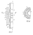
- FIG. 3 shows the second embodiment of the device according to the invention for generating acoustic vibrations
- Fig. 4 shows the section along line IV-IV of Fig. 3;
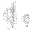
- FIG. 5 shows a third embodiment of the device according to the invention for generating acoustic vibrations
- FIG. 6 shows the section along line VI - VI of FIG. 5;
- FIG. 7 shows a fourth embodiment of the device according to the invention for generating acoustic vibrations (in longitudinal section);
- FIG. 9 shows a fifth embodiment of the device according to the invention for generating acoustic vibrations (in longitudinal section;
- the device for generating acoustic vibrations contains a housing (FIG. 1), which consists of joined flanges 1 and 2, the flange 1 with a nozzle 3 for supplying the liquid medium and the flange 2 with a nozzle 4 is provided for the discharge of the liquid medium.
- a stator 5 is attached, which is designed in the form of a cylindrical sleeve, the end parts an outer diameter is smaller than the outer diameter of the central part of the cylindrical bushing of the stator 5, and an external thread is formed on the end parts of the cylindrical bushing of the stator 5.
- One of the end parts of the cylindrical socket of the stator is screwed into the flange 1 of the housing.
- the outer side surface of the central part of the cylindrical bushing of the stator 5 is surrounded by a rotor 6, which is also in the form of a cylindrical bushing, leaving a gap.
- a closure 7 On the side opposite the flange 1, the end faces of the stator 5 and the rotor 6 are delimited by a closure 7, which is connected to the second end part of the cylindrical bushing of the stator 5 by means of a threaded connection.
- the generatrix of the side surface of the cylindrical bush of the rotor 6 is slightly smaller than the generatrix of the central part of the cylindrical bush of the stator 5, as a result of which the rotor 6 is arranged with a gap in relation to the end face of the flange 1 and the end face of the closure 7, so that its free rotation is ensured during the work of the device.
- two rows of through channels 8 and 9 are made.
- the number "Z p " of the channels 8, which are located in the side surface of the cylindrical sleeve of the rotor 6, is greater than the number "Z c " of the channels 9, which are located in the side surface of the central part of the cylindrical sleeve 5, the channels 9 in the side surface of the central part of the cylindrical sleeve of the stator 5 are made radially, while the channels 8 in the side surface of the cylindrical sleeve of the rotor 6 are made tangential.
- the radial channels 9 are formed on the stator 5 by three sections, two of which are carried out on the outer and the inner side surface of the central part of the cylindrical socket of the stator 5 substantially parallel to the longitudinal axis of the stator 5 and by means of a third radial section are connected.
- the tangential channels 8 on the side surface of the cylindrical sleeve of the rotor 6 are also formed by three sections, two of which are each carried out on the outer and inner side surface of the cylindrical sleeve of the rotor 6, the longitudinal axis of each of which is substantially parallel to the Is the longitudinal axis of the rotor 6 and wherein they are interconnected by means of a third tangential section.
- the number of radial and tangential channels 9, 8, which are evenly arranged in a row in the stator 5 and on the rotor 6, is designed so that at least one tangential channel 8 of the rotor 6 always matches a radial channel 9 of the stator 5.
- the radial channels 9 in the side surface of the central part of the cylindrical bushing of the stator 5 have the same width in cross section over the entire length of the radial channel 9, while the tangential channels 8 on the inner side surface of the cylindrical bushing of the rotor 6 have a width that is the same as the width the radial channels 9 on the side surface of the central part of the cylindrical bushing of the stator 5 is the same and decreases depending on the inclination of the axis of the tangential channel 8 from the radial direction to the periphery.
- the flanges 1 and 2 of the housing, the generatrix of the rotor 6 and the outer surface of the closure 7 form a cavity A which communicates with the connector 4 for the detection of the working medium and with the tangential channels 8 in the side surface of the cylindrical sleeve of the rotor 6 stands.
- the radial channels 9 in the cylindrical side surface of the bushing of the stator 5 and the tangential channels 8 in the cylindrical side surface of the bushing of the rotor 6 are called, for brevity, channels 9 of the stator 5 and channels 8 of the rotor 6.
- the liquid medium is supplied to the interior 10 (FIG. 2) of the cylindrical bushing of the stator 5 via the nozzle 3 (FIG. 1).
- the ge in the cavity 10 of the stator 5 Pumped liquid medium fills all radial channels 9 of the stator 5 and strives to flow through those tangential channels 8 of the rotor that coincide or partially coincide with the radial channels 9 of the stator 5.
- the liquid medium is always striving to move the rotor 6 comprising the stator 5 along the circumference.
- the rotor 6 is rotated by the forces of the liquid medium which are applied to the inclined surface of the tangential portion of the channel 8 of the rotor 6, and at Exit of the liquid medium from the channels 8 of the rotor 6, when the cross section of the collapsed channels is maximum, also by the reactive forces of the liquid medium which flows out of the channels 8 essentially along a tangent to the cylindrical outer surface of the rotor.
- the width of the radial sections of the channels 9 in the stator 5 is greater than the width of the tangential sections of the channels 8 in the rotor 6, which is why the velocity of the outflow of the liquid medium in the channels 8 increases when they match the channels 9.
- the construction of the device for generating acoustic vibrations undergoes a certain change.
- the inner cavity of the cylindrical bushing of the stator 11 (FIG. 3) is divided by a blind partition wall 12, which is arranged symmetrically with respect to two rows of continuous radial channels 13 of the stator 11 (FIG. 4).
- the outer side surface of the central part of the cylindrical bushing of the stator 11 (FIG. 3) is also covered while leaving a gap by a rotor 14, while the end faces of the stator 11 and the rotor 14 are limited by flanges 15 and 16 which are screwed onto the thread of the end parts of the cylindrical bushing of the stator 11.
- the generatrix of the cylindrical bushing of the rotor 14 is chosen to be smaller than the generatrix of the central part of the cylindrical bushing of the stator 11, as a result of which the rotor 14 is arranged with a gap with respect to the end faces of the flanges 15 and 16, thereby freeing it during rotation work is ensured.
- the inner cavity is the cylindrical socket of the stator 11, which is divided by the blind partition 12, forms two cavities 17 and 18, the cavity 17 with a nozzle 19 for the supply of the liquid medium and the cavity 18 with a nozzle 20 for the Discharge of the liquid medium is connected.
- Two rows of tangential channels 21 are embodied in the side surface of the cylindrical bushing of the rotor 14.
- one row of the tangential channels 21 of the rotor 14 is connected to the cavity 17 of the stator 11 by matching one row of the radial channels 13 of the stator 11, while the other row of the tangential channels 21, which are connected to the radial channels 13 Agreement comes, with the cavity 18 of the stator 11 is connected.
- Such an embodiment of the device allows the same or different liquid media to be conveyed simultaneously into the cavities 17 and 18 according to their structure and the device itself can be immersed directly in a liquid medium which is mixed with liquid media having the same or different structure .
- the number of channels 13 and 21 in the respective row can be the same or different. With the same number of channels 13 and 21 in the rows of the stator 11 and the rotor 14, the frequency of the acoustic vibrations corresponds to that of one row to the frequency of the vibrations of the other row. In those cases when the number of channels 13, 21 in the rows is different, each row of channels generates vibrations in the liquid medium with its own, of the frequency different from the other series, which is required to generate such acoustic vibrations in the third medium, which would ensure the presence of cavitation processes in the third medium.
- Such a design of the device allows physico-chemical and chemical-technological processes to be carried out with liquid media, the reaction to which depends on the degree of acoustic influence and which have a selectivity of contacting with one another depending on the speed of the intermediate phase state.
- the variations of the process are simplified in that the outflow of the components of the other liquid media from the cavities 17 and 18 into the total volume of the liquid medium in which the device is immersed is actually superimposed on the vibration effect of each row of the channels, and the acoustic field generated in the third medium is, according to its acoustic characteristics, dependent on the hydraulic characteristics of the liquid media conveyed into the cavities 17 and 18 of the device.
- a third embodiment of the device according to the invention for generating acoustic vibrations is possible.
- the device is additionally provided with a stator 22 and a rotor 23 (FIG. 5), which are arranged in the housing coaxially with the main stator 5 and the main rotor 6 and are separated from them by a blind partition wall 24.
- a mixing chamber 25 is provided in the device housing, which is connected to the continuous tangential channels 8 and 26 of the respective rotors 6 and 23 and with a nozzle 27 for the discharge of the liquid medium and is delimited by housing walls 28, 29 and a jacket section 30, which is connected via its end faces to the housing walls 28, 29 of the housing and has an opening 31 which is connected to the connecting piece 27.
- the walls 28, 29 of the housing are each with Stubs 32 and 33 are provided for the supply of the liquid medium into the cavities 34, 35 of the stators 5 and 22, respectively.
- One end part of the stator 5 is screwed into the housing wall 28, while the other end part of the stator 5 is screwed into the blind partition wall 24.
- one end part of the stator 22 is screwed into the blind partition 24 and the other end part of the stator 22 is screwed into the housing wall 29.
- Continuous radial channels 36 are embodied in the side surface of the central part of the cylindrical bushing of the stator 22, which are identical to the channels 9 in the side surface of the central part of the cylindrical bushing of the stator 5.
- a cavity “B" (FIG. 6) is formed on the cylindrical surface of the stators 5 and 22 between the rubbing of the continuous channels 9 and 36 by means of a ring turning, which cavity has radial channels 37, the number of which can be divided by three the cavities 34, 35 (Fig. 5) is connected. Thanks to these channels 37 (FIGS. 5, 6), the working medium is always present in the cavity "B", which is conveyed from the cavities 34 and 35 by an external pressure source of the medium and after leakage flows over the gap between the cylindrical surfaces of the stator 5 , 22 and the rotor 6, 23 strives. In this way, the fluid friction between the side surfaces of the cylindrical bushes of the rotors 6 and 23 and the stators 5 and 22 is ensured.
- the components of the liquid media are conveyed separately into the cavities 34 and 35 via the respective nozzles 32 and 33.
- the liquid media pass through the channels 9, 8 and 36, 26 into the cavity 25 and flow through the opening 31 and the nozzle 27 into the corresponding main line.
- the rotors 6 and 23 are rotated at a certain speed, which depends on the pressure of the liquid medium.
- 25 acoustic vibrations with corresponding Fre frequency and intensity.
- a fourth embodiment of the device according to the invention for generating acoustic vibrations is possible.
- a stepped cylindrical housing 38 (FIG. 7) is provided with a cover 39, to which a stator 40 is rigidly attached, which is designed in the form of a cylindrical sleeve which is closed on one end face and two rows in the side face are carried out by continuous radial channels 41, while between the rows of these channels 41 there is a ring turning, the cavity of which is connected by means of continuous radial channels 42, the number of which is divisible by three, to the inner cavity 43 of the cylindrical socket of the stator 40, which cavity with a nozzle 44 is connected to the supply of the liquid medium.
- the stator 40 which is arranged in the first stage of the housing 38, can be made in one piece with the cover 39.
- the cylindrical outer surface of the sleeve of the stator 40 is surrounded by the cylindrical sleeve of a rotor 45, which is made in one piece with a drive shaft 46, while the drive shaft 46 is fixed in the second stage of the cylindrical housing 38 in a bearing 47.
- the rotor 45 is arranged leaving a gap with respect to the cover 39, which gap ensures its rotation relative to the stator 40.
- Two rows of tangential channels 48 (FIG. 8) are made in the side face of the cylindrical bushing of the rotor 45.
- the outer side surface of the cylindrical bushing of the The rotor 45, the cover 39 (FIG. 7) and the first stage of the cylindrical housing 38 form a cavity "C", into which the liquid medium passes through the channels 48 of the rotor 45.
- an opening 49 is provided in the side surface of the first stage of the cylindrical housing which is connected to a nozzle 50 for the discharge of the liquid medium. Leakage of the working fluid from chamber "C" into the bearing 47 is prevented by means of a labyrinth seal 51 and a cavity 52, which is formed by a recess in the side surface of the second stage of the cylindrical housing 38 and a channel 53 connected to the cavity 52 is.
- the rotor 45 is rotated by means of a rotary drive (not shown in the drawing) which is connected to the drive shaft 46.
- the generation of acoustic vibrations in the cavity "C" of this variant is similar to the variants described above.
- the distinguishing feature of this design is that the rotor 45 has two bearings: a sliding and a roller bearing.
- the bearing 47 functions as one of the bearings, while the contacting cylindrical surfaces of the stator 40 and the rotor 45 serve as another bearing. This allows the gap between surfaces of the rotor 45 and the stator 40 to be reduced to a minimum. As a result, transit flows of the liquid medium in the gap are excluded, which has a positive effect on the implementation of physico-chemical processes with viscous media thanks to the increase in the vibration amplitude and the reduction in the loads on the rotary drive.
- Another possible embodiment of the device for generating acoustic vibrations with forced rotation of the rotor is Another possible embodiment of the device for generating acoustic vibrations with forced rotation of the rotor.
- housing 54 (FIG. 9) in the form of a half torus with flanges 55 and 56 on its side surface, to which flanges are coaxial with the housing 54 respective covers 57 and 58 are tightly connected.
- the stator consists of two axially spaced cylindrical bushes 59 and 60 with radial channels 61 formed therein.
- the cylindrical bushes 59 and 60 are rigidly connected to the housing 54 and the covers 57 and 58, and the cylindrical bushing 62 of the rotor 63 is also connected a drive shaft 64 connected via a stiffening rib 65 which is fixed to the inner surface of the cylindrical sleeve 62 of the rotor 63 symmetrically between the rows of continuous tangential channels 66 (FIG. 10) which are made on the surface of the cylindrical sleeve 62.
- the stiffening rib 65 (FIG. 9) of the rotor 63 is located in the space between the cylindrical bushes 59 and 60.
- the liquid media are supplied via nozzles 69 and 70 for supplying the liquid medium into the cavities 71 and 72 formed by the surfaces of the covers 57 and 58 and the stiffening rib 65 of the rotor 63.
- the leakage flows of the liquid medium from the cavity 72 are prevented by a seal 76 arranged in the bearing 68.
- Such a construction of the device is necessary in the case of the use of particularly viscous liquid media and ensures a highly productive throughput of the liquid working medium, the work of the device not being dependent on the temperature conditions when carrying out the chemical-technological processes.
- the invention can be used in any branch of industrial production where the processes of mixing difficult-to-mix components, dispersing, dissolving, producing oil-in-water emulsions and water-in-oil emulsions, of suspensions or homogeneous liquids is required to intensify technological processes in liquid media.
Landscapes
- Physics & Mathematics (AREA)
- Engineering & Computer Science (AREA)
- Acoustics & Sound (AREA)
- Multimedia (AREA)
- Nitrogen And Oxygen Or Sulfur-Condensed Heterocyclic Ring Systems (AREA)
- Structures Of Non-Positive Displacement Pumps (AREA)
- Mixers With Rotating Receptacles And Mixers With Vibration Mechanisms (AREA)
- Apparatuses For Generation Of Mechanical Vibrations (AREA)
Abstract
Applications Claiming Priority (1)
| Application Number | Priority Date | Filing Date | Title |
|---|---|---|---|
| PCT/SU1988/000199 WO1990004721A1 (fr) | 1988-10-18 | 1988-10-18 | Dispositif pour generer des oscillations acoustiques dans un milieu liquide |
Publications (2)
| Publication Number | Publication Date |
|---|---|
| EP0420981A1 true EP0420981A1 (fr) | 1991-04-10 |
| EP0420981A4 EP0420981A4 (en) | 1991-04-24 |
Family
ID=21617318
Family Applications (1)
| Application Number | Title | Priority Date | Filing Date |
|---|---|---|---|
| EP19890903486 Withdrawn EP0420981A4 (en) | 1988-10-18 | 1988-10-18 | Device for generating acoustic oscillations in a liquid medium |
Country Status (4)
| Country | Link |
|---|---|
| EP (1) | EP0420981A4 (fr) |
| JP (1) | JPH03501703A (fr) |
| FI (1) | FI903040A0 (fr) |
| WO (1) | WO1990004721A1 (fr) |
Cited By (7)
| Publication number | Priority date | Publication date | Assignee | Title |
|---|---|---|---|---|
| RU2284229C2 (ru) * | 2004-04-28 | 2006-09-27 | Институт проблем машиноведения Российской академии наук | Гидроакустическая сирена |
| RU2344001C2 (ru) * | 2007-03-09 | 2009-01-20 | Институт проблем машиноведения Российской академии наук | Сирена встречных резонансных волн |
| RU2358812C1 (ru) * | 2007-11-06 | 2009-06-20 | Евгений Дмитриевич Свияженинов | Сирена встречных резонансных волн, снимаемых с единого однородного по длине ротора |
| RU2399433C1 (ru) * | 2009-11-09 | 2010-09-20 | Сергей Витальевич Матвеев | Автороторный преобразователь жидкости |
| WO2016165917A1 (fr) * | 2015-04-17 | 2016-10-20 | Bühler AG | Dispositif et procédé de mélange, en particulier de dispersion |
| RU175742U1 (ru) * | 2017-06-05 | 2017-12-18 | Федеральное государственное автономное образовательное учреждение высшего образования "Южно-Уральский государственный университет (национальный исследовательский университет)" (ФГАОУ ВО "ЮУрГУ (НИУ)") | Гидроакустический аппарат с модуляцией потока |
| RU2679666C1 (ru) * | 2018-04-10 | 2019-02-12 | Евгений Дмитриевич Свияженинов | Генератор резонансных вращающихся акустических волн |
Family Cites Families (12)
| Publication number | Priority date | Publication date | Assignee | Title |
|---|---|---|---|---|
| FR460581A (fr) * | 1912-07-29 | 1913-12-05 | Signal Gmbh | Sirène sous-marine mobile |
| GB716533A (en) * | 1952-09-24 | 1954-10-06 | Niro Atomizer As | Improvements in or relating to atomizers with rotating vanes |
| DE1040513B (de) * | 1953-09-07 | 1958-10-09 | Wilhelm Schmitz | Misch- und Emulgiervorrichtung fuer Fluessigkeiten |
| DE1026107B (de) * | 1955-06-27 | 1958-03-13 | Giovanola Freres Sa | Einrichtung zur akustischen Behandlung von fluessigen Medien |
| GB891152A (en) * | 1957-11-21 | 1962-03-14 | Peter Willems | A method and apparatus for continuously changing the structure of substances or mixtures of such substances |
| FR1249337A (fr) * | 1959-11-10 | 1960-12-30 | Procédé et dispositif de traitement à fréquence sonore ou ultra-sonore de substances portées par un support fluide | |
| US3195867A (en) * | 1962-01-23 | 1965-07-20 | Liberty Nat Bank And Trust Com | Homogenizing apparatus |
| DE2330469A1 (de) * | 1973-06-15 | 1975-01-16 | Janke & Kunkel Kg | Vorrichtung zur herstellung von dispersionen, suspensionen, emulsionen und loesungen aus stoffgemischen verschiedener aggregatzustaende |
| CH604931A5 (en) * | 1975-05-02 | 1978-09-15 | Vladimir Matveevich Varlamov | Acoustic vibration generator for liquid current |
| GB1578018A (en) * | 1976-03-11 | 1980-10-29 | Schmermund A | Glue applications |
| FI61814C (fi) * | 1980-07-22 | 1982-10-11 | Finnreg Oy | Emulgeringsanordning |
| DE3123843C2 (de) * | 1981-06-16 | 1987-05-14 | Samson Ag, 6000 Frankfurt | Klappenventil |
-
1988
- 1988-10-18 JP JP1503239A patent/JPH03501703A/ja active Pending
- 1988-10-18 FI FI903040A patent/FI903040A0/fi not_active Application Discontinuation
- 1988-10-18 WO PCT/SU1988/000199 patent/WO1990004721A1/fr not_active Ceased
- 1988-10-18 EP EP19890903486 patent/EP0420981A4/ru not_active Withdrawn
Cited By (10)
| Publication number | Priority date | Publication date | Assignee | Title |
|---|---|---|---|---|
| RU2284229C2 (ru) * | 2004-04-28 | 2006-09-27 | Институт проблем машиноведения Российской академии наук | Гидроакустическая сирена |
| RU2344001C2 (ru) * | 2007-03-09 | 2009-01-20 | Институт проблем машиноведения Российской академии наук | Сирена встречных резонансных волн |
| RU2344001C9 (ru) * | 2007-03-09 | 2009-07-10 | Институт проблем машиноведения Российской академии наук | Сирена встречных резонансных волн |
| RU2358812C1 (ru) * | 2007-11-06 | 2009-06-20 | Евгений Дмитриевич Свияженинов | Сирена встречных резонансных волн, снимаемых с единого однородного по длине ротора |
| RU2399433C1 (ru) * | 2009-11-09 | 2010-09-20 | Сергей Витальевич Матвеев | Автороторный преобразователь жидкости |
| WO2016165917A1 (fr) * | 2015-04-17 | 2016-10-20 | Bühler AG | Dispositif et procédé de mélange, en particulier de dispersion |
| RU2699108C2 (ru) * | 2015-04-17 | 2019-09-03 | Бюлер Аг | Устройство и способ для смешивания, в частности, для диспергирования |
| US11059004B2 (en) | 2015-04-17 | 2021-07-13 | Buehler Ag | Device and method for mixing, in particular dispersing |
| RU175742U1 (ru) * | 2017-06-05 | 2017-12-18 | Федеральное государственное автономное образовательное учреждение высшего образования "Южно-Уральский государственный университет (национальный исследовательский университет)" (ФГАОУ ВО "ЮУрГУ (НИУ)") | Гидроакустический аппарат с модуляцией потока |
| RU2679666C1 (ru) * | 2018-04-10 | 2019-02-12 | Евгений Дмитриевич Свияженинов | Генератор резонансных вращающихся акустических волн |
Also Published As
| Publication number | Publication date |
|---|---|
| FI903040A7 (fi) | 1990-06-15 |
| JPH03501703A (ja) | 1991-04-18 |
| WO1990004721A1 (fr) | 1990-05-03 |
| FI903040A0 (fi) | 1990-06-15 |
| EP0420981A4 (en) | 1991-04-24 |
Similar Documents
| Publication | Publication Date | Title |
|---|---|---|
| DE60120738T2 (de) | Dynamischer mischer | |
| EP1781402B1 (fr) | Dispositif pour produire par une action mecanique douce des micro et nanoemulsions finement dispersees a distribution dimensionnelle etroite des gouttes | |
| EP0512331A1 (fr) | Dispositif pour nettoyer la zone proche du trou de sondage | |
| EP0379654A1 (fr) | Injecteur rotatif pour outil de nettoyage haute pression | |
| DE2549314A1 (de) | Dekantier-zentrifuge | |
| DE69004087T2 (de) | Flüssigkeitsringmaschinen. | |
| DE2365057A1 (de) | Druckmittelbetaetigte maschine, insbesondere parallel- und innenachsige rotationskolbenkraftmaschine oder -pumpe mit kaemmeingriff | |
| EP0850106A1 (fr) | Dispositif et procede de dispersion | |
| AT395871B (de) | Vorrichtung zum sieben einer zellulosefaserbrei-suspension | |
| DE2918547A1 (de) | Rotations-arbeitsmitteldruckvorrichtung | |
| DE3413675A1 (de) | Vorrichtung zum dispergieren bzw. emulgieren einer aus wenigstens zwei produkten bestehenden menge | |
| EP1164293B1 (fr) | Pompe ? engrenages avec dispositif de nettoyage | |
| DE69716552T2 (de) | Dichtung/lagervorrichtung | |
| EP4072737B1 (fr) | Appareil de nettoyage | |
| DE2064704C3 (de) | Zentrifuge zur Reinigung eines Betnebsmittels einer Kolbenbrennkraft maschine | |
| DE69300999T2 (de) | Innenzahnradpumpe mit regelbarer Liefermenge | |
| EP1923113A1 (fr) | Centrifugeuse | |
| DE60012900T2 (de) | Mischvorrichtung | |
| DE3008832C2 (fr) | ||
| DE3522087C2 (fr) | ||
| DE1528985A1 (de) | Ventilordnung fuer hydraulische Druckvorrichtung | |
| DE2521015C3 (de) | Vorrichtung zur Erzeugung von akustischen Schwingungen in einem flüssigen Medium | |
| EP0696679B1 (fr) | Pompe à engrenages pour le refoulement de laque | |
| EP4062066B1 (fr) | Machine à fluide, en particulier machine hydraulique | |
| CH604931A5 (en) | Acoustic vibration generator for liquid current |
Legal Events
| Date | Code | Title | Description |
|---|---|---|---|
| PUAI | Public reference made under article 153(3) epc to a published international application that has entered the european phase |
Free format text: ORIGINAL CODE: 0009012 |
|
| 17P | Request for examination filed |
Effective date: 19900609 |
|
| AK | Designated contracting states |
Kind code of ref document: A1 Designated state(s): CH DE FR IT LI SE |
|
| A4 | Supplementary search report drawn up and despatched |
Effective date: 19910306 |
|
| AK | Designated contracting states |
Kind code of ref document: A4 Designated state(s): CH DE FR IT LI SE |
|
| 16A | New documents despatched to applicant after publication of the search report | ||
| 17Q | First examination report despatched |
Effective date: 19920512 |
|
| STAA | Information on the status of an ep patent application or granted ep patent |
Free format text: STATUS: THE APPLICATION IS DEEMED TO BE WITHDRAWN |
|
| 18D | Application deemed to be withdrawn |
Effective date: 19920923 |