EP0421007A1 - Dispositif de réanimation - Google Patents
Dispositif de réanimation Download PDFInfo
- Publication number
- EP0421007A1 EP0421007A1 EP89118366A EP89118366A EP0421007A1 EP 0421007 A1 EP0421007 A1 EP 0421007A1 EP 89118366 A EP89118366 A EP 89118366A EP 89118366 A EP89118366 A EP 89118366A EP 0421007 A1 EP0421007 A1 EP 0421007A1
- Authority
- EP
- European Patent Office
- Prior art keywords
- chamber
- gas
- delivery
- housing
- communication
- Prior art date
- Legal status (The legal status is an assumption and is not a legal conclusion. Google has not performed a legal analysis and makes no representation as to the accuracy of the status listed.)
- Withdrawn
Links
- 239000007789 gas Substances 0.000 claims abstract description 92
- 239000011800 void material Substances 0.000 claims abstract description 18
- 210000002345 respiratory system Anatomy 0.000 claims abstract description 15
- 230000006835 compression Effects 0.000 claims abstract description 11
- 238000007906 compression Methods 0.000 claims abstract description 11
- 239000000203 mixture Substances 0.000 claims abstract description 8
- 230000015572 biosynthetic process Effects 0.000 claims abstract description 4
- 238000007789 sealing Methods 0.000 claims description 7
- 230000007246 mechanism Effects 0.000 abstract description 4
- 230000001105 regulatory effect Effects 0.000 abstract description 4
- 230000036541 health Effects 0.000 description 7
- 210000004072 lung Anatomy 0.000 description 6
- 238000013459 approach Methods 0.000 description 4
- 210000003811 finger Anatomy 0.000 description 4
- 230000007935 neutral effect Effects 0.000 description 4
- 210000003127 knee Anatomy 0.000 description 3
- CURLTUGMZLYLDI-UHFFFAOYSA-N Carbon dioxide Chemical compound O=C=O CURLTUGMZLYLDI-UHFFFAOYSA-N 0.000 description 2
- -1 e.g. Polymers 0.000 description 2
- 210000004247 hand Anatomy 0.000 description 2
- 239000000463 material Substances 0.000 description 2
- 238000000034 method Methods 0.000 description 2
- 210000003813 thumb Anatomy 0.000 description 2
- 235000007754 Achillea millefolium Nutrition 0.000 description 1
- 240000000073 Achillea millefolium Species 0.000 description 1
- 239000004698 Polyethylene Substances 0.000 description 1
- 239000008280 blood Substances 0.000 description 1
- 210000004369 blood Anatomy 0.000 description 1
- 229910002092 carbon dioxide Inorganic materials 0.000 description 1
- 239000001569 carbon dioxide Substances 0.000 description 1
- 230000003247 decreasing effect Effects 0.000 description 1
- 239000006260 foam Substances 0.000 description 1
- 238000012986 modification Methods 0.000 description 1
- 230000004048 modification Effects 0.000 description 1
- 210000003300 oropharynx Anatomy 0.000 description 1
- 239000004033 plastic Substances 0.000 description 1
- 229920003023 plastic Polymers 0.000 description 1
- 229920000573 polyethylene Polymers 0.000 description 1
- 230000008569 process Effects 0.000 description 1
- 230000009467 reduction Effects 0.000 description 1
- 230000000241 respiratory effect Effects 0.000 description 1
- 230000029058 respiratory gaseous exchange Effects 0.000 description 1
- 229920001169 thermoplastic Polymers 0.000 description 1
- 239000004416 thermosoftening plastic Substances 0.000 description 1
- 238000009423 ventilation Methods 0.000 description 1
Images





Classifications
-
- A—HUMAN NECESSITIES
- A61—MEDICAL OR VETERINARY SCIENCE; HYGIENE
- A61M—DEVICES FOR INTRODUCING MEDIA INTO, OR ONTO, THE BODY; DEVICES FOR TRANSDUCING BODY MEDIA OR FOR TAKING MEDIA FROM THE BODY; DEVICES FOR PRODUCING OR ENDING SLEEP OR STUPOR
- A61M16/00—Devices for influencing the respiratory system of patients by gas treatment, e.g. ventilators; Tracheal tubes
- A61M16/0057—Pumps therefor
- A61M16/0075—Bellows-type
-
- A—HUMAN NECESSITIES
- A61—MEDICAL OR VETERINARY SCIENCE; HYGIENE
- A61M—DEVICES FOR INTRODUCING MEDIA INTO, OR ONTO, THE BODY; DEVICES FOR TRANSDUCING BODY MEDIA OR FOR TAKING MEDIA FROM THE BODY; DEVICES FOR PRODUCING OR ENDING SLEEP OR STUPOR
- A61M16/00—Devices for influencing the respiratory system of patients by gas treatment, e.g. ventilators; Tracheal tubes
- A61M16/0057—Pumps therefor
- A61M16/0084—Pumps therefor self-reinflatable by elasticity, e.g. resuscitation squeeze bags
Definitions
- This invention relates to manually-operated resuscitators and other devices for providing air or other appropriate gas or mixture of gases to the respiratory tract of an individual during emergency medical treatment.
- this invention relates to a single-hand resuscitation device for providing gas to the respiratory tract of an individual.
- bag-valve-mask device In many emergency medical situations it is necessary to assist the patient's breathing. When sophisticated respiratory instruments are not available, assistance is usually provided by a "portable resuscitator,” “bag-valve-mask device” or “bag-mask ventilator.”
- Prior art bag-mask resuscitators consist of a plastic or rubber face mask, a valve/conduit and a bag.
- the face mask conforms to the general contours of a human face, lips, teeth and/or gums (i.e., all or part of the maxillo-facial region) to facilitate fitting the mask to the patient.
- the valve/conduit is usually a generally L-shaped tube which is placed between the mask and the bag.
- the valve/conduit may contain one or more valves which regulate gas flow through the valve/conduit in both directions.
- the bag forms a compressible chamber which usually holds 1,000-1,600 ml of gas when filled. When the bag is compressed, gas passes out of the bag through the valve/conduit and to the patient through the mask.
- Prior art devices of this nature are typified by the Laerdal Portable Resuscitator, the Ambu® Universal Resuscitator MS-30 and the Hope II Resuscitator (all commercially available from Dynamed, Inc., 6200 Yarrow Drive, Carlsbad, California 92008, product nos. E09570, E21226 and E17236, respectively).
- the head and neck should be hyperextended, thus lifting the jaw, moving the tongue forward and creating only one angle for gas to travel around to reach the respiratory tract.
- the health professional is also trying to maintain a good seal between the mask and the patient's maxillo-facial region, he continually exerts a downward pressure against the maxillo-facial region, particularly the jaw. This downward force tends to push the patient's head and neck into a neutral or flexed position.
- Another suggested approach uses the health professional's knees to hold the head and neck in the hyperextended position while using one hand to form a seal between the mask and the patient's maxillo-facial region. This solution is also only partially effective because it cannot be conveniently used where the patient is not on the ground or other surface onto which the health professional can climb to use his knees.
- the second major problem associated with the traditional mask resuscitators is their inability to deliver a constant acceptable volume of gas to the patient.
- damage can be done to the patient's lungs if too much gas is delivered, especially when the patient is a smaller individual, e.g.. a child.
- the American Heart Association has established 800 ml as the standard volume of gas which should be delivered to an adult with each ventilation using a resuscitator.
- the traditional resuscitation device bags usually have a volume over one liter and are not calibrated to let the health professional know how much gas is being delivered.
- a resuscitation device for delivering air or other appropriate gas or mixture of gases to the respiratory tract of a patient which can be utilized using only one hand to operate the device, leaving the other hand completely free to manipulate the patient's head and neck.
- the device comprises a housing defining a chamber, means for delivering gas from the chamber to the patient and means for filling the chamber with gas.
- the delivery means is usually a mask or a mask combined with a conduit connecting the chamber to the mask.
- the housing and delivery means are oriented with respect to each other such that during operation of the device force or forces applied to the device through the single operating hand selectively compresses the chamber so as to deliver a prescribed volume of gas to the respiratory tract of the individual, causes formation of a substantial seal between the delivery means (e.g., mask) and the maxillo-facial region of the individual during the compression of the chamber, and maintains or releases the seal during refilling of the chamber.
- the delivery means e.g., mask
- the maxillo-facial region of the individual during the compression of the chamber, and maintains or releases the seal during refilling of the chamber.
- the device can also include means for limiting the void volume of the chamber or for limiting the degree to which the chamber may be compressed (delivery-limiting), thus regulating the volume of gas delivered to the patient.
- the housing 21 in its unassembled and fully extended form is a hollow elongated "accordion-like" structure having a generally oval-shaped cross section and closed ends 22.
- the housing 21 is 8.2 inches long when fully extended and the cross sectional dimensions are 8.0 inches along the long axis and 5.6 inches along the short axis.
- the housing 21 is sectioned into two end baffles 23, two intermediate baffles 24 and one central baffle 25.
- the central baffle 25 is 1.2 inches wide, the intermediate baffles 24 are each 1.5 inches wide, and the end baffles 23 are each 0.5 inches wide, with width being measured along the length of the housing 21.
- a grip 28 is molded into the surface of each closed end 22 of the housing 21.
- the housing 21 can be made from any flexible material which is substantially impermeable to gas, the housing 21 of the preferred embodiment was blow-molded from a thermoplastic, e.g., polyethylene.
- the housing 21 is hollow and defines a compressible chamber 26 as shown in Figs. 1 and 2.
- a delivery manifold 27 of cross sectional diameter 0.86 inches is located on one of the long sides of the central baffle 25 as shown in Fig. 2.
- the delivery manifold 27 extends through the housing 21 into the chamber 26 such that compression of the chamber 26 will cause gas to pass through the delivery manifold 27.
- the chamber filling means of the preferred embodiment is a filling manifold 35 located on one of the short sides of the central baffle 25, the filling manifold 35 being fitted with a one-way valve 36 which only allows gas to pass into the chamber as it is refilled.
- filling means Other means for filling the chamber with gas which are known to those skilled in the art but not specifically disclosed herein are intended to be included within the term "filling means" as that term is used in the appended claims so long as such filling means can be oriented with respect to the other elements of the devices of the present invention so as to allow single-handed delivery of gas to the patient and sealing with the patient's maxillo-facial region as described below and in the appended claims.
- the housing 21 is partially compressed by two springs 29 into a bellows-like configuration.
- the springs 29 are crafted from heavy wire to have the general shape shown in Fig. 1. Starting at one end of the spring 29, the wire extends 0.1 inches, then turns 90 degrees to the right and extends 2.9 inches, then turns 58 degrees to the left and extends 1.3 inches, then turns 58 degrees to the left and extends 2.9 inches, and finally turns 90 degrees to the right and extends 0.1 inches to the other end of the spring 29. Both ends of each spring 29 have a hook31.
- one edge of the housing 21 is compressed and the generally right-angled segment of the springs 29 are placed over the edge of the housing 21 at two positions 30 such that (1) the compressed edge of the housing 21 remains compressed and (2) the free ends of the springs 29 extend away from the ends 22 of the housing 21.
- the hooks 31 at both ends of each spring 29 are then hooked over the end baffle 23 at four positions 32 (only one shown in Fig. 1).
- the form of the springs 29 holds the housing 21 open in a bellows-like configuration as shown in Fig. 2.
- the springs 29 also resist full compression of the housing 21 during use and pull the housing 21 into its "open" position when compressive forces are not being applied to the ends 22 of the housing 21.
- the preferred embodiment has delivery means for delivering gas to the patient which includes a conduit 33 and a mask 34, A conduit 33 of diameter 0.86 inches and 6.0 inches long is connected to the housing 21, as shown in Fig. 2, such that gas passing through the delivery manifold 27 passes through the conduit 33.
- the conduit 33 may, but need not necessarily, contain valves and outlets for regulating the direction of gas flow through the conduit 33.
- the preferred embodiment incorporates a one-way valve 70 and an exhaust 71.
- the one-way valve 70 allows gas to pass from the chamber to the mask and prevents gas from passing from the patient's lungs back into the chamber. Gas leaving the patient's lungs is expelled through exhaust 71.
- the conduit 33 is attached at its other end to a mask 34, as shown in Fig. 2.
- a mask 34 is attached at its other end to a mask 34, as shown in Fig. 2.
- the delivery means can include other means for introducing gas to the respiratory tract, e.g., an endotracheal tube or esophageal obturator airway.
- delivery means means for delivering gas to the patient which are known to those skilled in the art but not specifically disclosed herein are intended to be included within the term "delivery means" as that term is used in the appended claims so long as such delivery means can be oriented with respect to the other elements of the devices of the present invention so as to allow single-handed delivery of gas to the patient and sealing with the patient's maxillo-facial region as described below and in the appended claims.
- Figs. 5 and 6 depict an alternative embodiment of the housing of the device of the present invention.
- the alternative housing 41 is, unlike the preferred embodiment, formed as a "true" bellows having two closed ends 42 of generally rectangular cross section having dimensions 8.0 inches by 5.0 inches.
- the ends 42 are each joined at one edge to a central baffle 45.
- the other edges of the ends 42 are each joined to an end baffle 43.
- the end baffles 43 are in turn joined to the central baffle 45.
- the central baffle 45 is 1.2 inches wide and the end baffles 43 are each 3.0 inches wide.
- a grip 48 is formed on the surface of each end 42 of the alternative housing 41.
- the alternative housing 41 incorporates a delivery manifold 47 which is located on one of the long sides of the central baffle 45. Delivery means described above are also useful in this alternative embodiment.
- the alternative housing 41 also incorporates as filling means a filling manifold (not shown) and a filling valve 46 which is located on one of the short sides of the central baffle 45 similar to the corresponding structure in the preferred embodiment.
- the filling means in a device of the present invention can be located at other locations on the housing or at a location not on the housing (e.g., on the conduit leading from the chamber to the mask). When the filling means is not located on the housing, gas flow throughout the device should be properly regulated so as to the chamber is refilled with fresh gas and not with gas from the patient's lungs.
- the alternative housing 41 does not, however, have two springs like those of the preferred embodiment. Compression of the housing is resisted by a single coiled spring 50 shown in Fig. 5.
- the spring 50 pushes the alternative housing 41 into the expanded position when no compressive forces are applied to the housing.
- the expanded position can be maintained by including some internal form (e.g., foam, sponge, etc.) inside the housing.
- the alternative housing 41 can be made from any flexible material which is substantially impermeable to gas, the alternative housing 41 of this alternative embodiment was constructed from cardboard and other paper products.
- housing in a device of the present invention, which will be apparent to those skilled in the art but are not specifically disclosed herein, are intended to be included within the term "housing" as that term is used in the appended claims so long as such housing can be oriented with respect to the other elements of the devices of the present invention so as to allow single-handed delivery of gas to the patient and sealing with the patient's maxillo-facial region as described below and in the appended claims.
- the preferred embodiment of the device 20 of the present invention is also fitted with means for restricting the amount of gas which fills the chamber and, as a result, is delivered to the patient when the chamber is compressed.
- Each such void-limiting means can be used with most any embodiment of the device of the present invention.
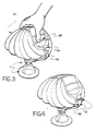
- Figs. 1, 3 and 4 show two ways of limiting the void volume of the expanded chamber.
- a punched strip 40 is attached at one end to one closed end of the housing and hangs free over most of the length of the strip.
- the punched strip 40 is inserted through slot 39 in the other closed end of the housing and engaged with tab 60 on housing 21 holding the notched strip 40 in place.
- FIG. 4 shows use of a velcro strip pair 37 and 38.
- One half of the velcro pair 37 is anchored over its entire length to one closed end of the housing.
- the other half of the velcro pair 38 is attached at one end to the other closed end of the housing and hangs free over most of the length of the strip.
- the free-hanging strip 38 is engaged with the anchored strip 37, thus preventing the housing from expanding wider than the length of the segment of the free-hanging strip 38 extending between the ends.
- the free-hanging strip 38 is marked at various places to indicate the void volume of the chamber allowed by engaging the velcro pair to that point on the free-hanging strip 38.
- Fig. 3 depicts the preferred method of operating the device 10 of the present invention.
- the palm of a single hand may be placed along the compressed or top edge of the housing 21.
- the thumb and fingers grab the device along the grips 28.
- the mask 34 is then placed over the patient's maxillo-facial region.
- the single hand then applies force to the device to form a seal between the mask 34 and the maxillo-facial region.
- compressive forces the directions of which are opposed to (i.e., in any direction other than in complete alignment with) the direction of the applied sealing force, to the ends 22 of the housing 21, thus compressing the chamber 26 and delivering the prescribed volume of gas through the mask 34 to the patient.
- the single hand releases the compressive forces on the housing, thus allowing the chamber 26 to refill through the filling manifolds 35.
- the applied sealing forces may be selectively maintained, or fully or partially released during the refilling process in order to maintain or release, as desired, the seal against the maxillo-facial region of the patient and maintain positive end expiratory pressure.
- the ability to both hold the device in place to achieve a seal and deliver compressive forces to the chamber with a single hand is one of the features that distinguishes the devices of the present invention over the prior art.
- the herein described embodiments of the devices of the present invention are also characterized by the fact that a virtually constant distance is maintained between the point on the device where the force is applied by the single hand and the patient's maxillo-facial region where that applied force results in formation of a seal.
- the embodiments described herein are characterized by that fact, the appended claims are not intended to be limited by such characteristic unless expressly stated in a given claim. Certain embodiments which are intended to be included within the coverage of some of the appended claims may not maintain such a constant distance. As long as a certain embodiment contains all of the elements and qualities described in an appended claim, that does not expressly require that such a constant distance be maintained, such embodiment is intended to be covered by such claim regardless of the fact that such a constant distance is not maintained in such embodiment.
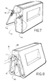
- Figs. 7-11 show five other mechanisms for limiting the void volume of the expanded chamber.
- hole 72 of tab 73 is engaged with pin 74 to reduce the volume to which the chamber can expand.
- slot 75 of tab 76 is engaged with pin 74 to limit the void volume of the chamber.
- pin 74 will be positioned within slot 75 toward the free end of tab 76 such that that half of the chamber is prevented from fully opening.
- pin 74 slides toward the other end of slot 75 until the void volume is completely delivered.
- pin 77 is engaged with holes 78 which correspond to different void volumes.
- pin 77 contacts ribs 80 and 81 preventing the housing from fully opening.
- pins 82 are engaged with clip 83 to prevent the chamber from fully expanding.
- the clip 83 can be moved to different sets of pins to vary the void volume.
- knob 84 is fitted with four internal recesses 85 which correspond to four different void volumes. When the chamber is compressed, knob 84 is pulled out, turned and pushed or pulled back in such that the internal recess corresponding to the desired void volume becomes engaged with pins 86. When the compressing force on the chamber is released, the ends of the internal recess prevent the chamber from fully expanding.
- one end of the device is fitted with a sliding member 87 which is attached to one end of string 88.
- String 88 runs through hole 89 and the other end of string 88 is attached at point 90 to the opposite end of the device.
- Sliding member 87 is then adjusted to shorten or lengthen the length of string 88 extending between hole 89 and point 90 to decrease and increase, respectively, the allowed void volume of the chamber.
- An embodiment of the present invention can also incorporate a mechanism for limiting the degree to which the housing and chamber can be compressed and, as a result, limit the volume of gas delivered to the patient.
- Figs. 12 and 13 show two possible delivery-limiting mechanisms for limiting the volume of gas delivered to the patient.
- sliding member 91 can be adjusted to various positions corresponding to various delivery volumes such that it blocks the complete compression of the chamber, thus delivering a limited volume of gas.
- pin 92 can be inserted in various holes 93 corresponding to various delivery volumes such that it blocks the complete compression of the chamber, thus delivering a limited volume of gas.
- Other delivery-limiting means may be used with the devices of the present invention and such other means are intended to fall within the scope of the invention.
Landscapes
- Health & Medical Sciences (AREA)
- Emergency Medicine (AREA)
- Pulmonology (AREA)
- Engineering & Computer Science (AREA)
- Anesthesiology (AREA)
- Biomedical Technology (AREA)
- Heart & Thoracic Surgery (AREA)
- Hematology (AREA)
- Life Sciences & Earth Sciences (AREA)
- Animal Behavior & Ethology (AREA)
- General Health & Medical Sciences (AREA)
- Public Health (AREA)
- Veterinary Medicine (AREA)
- Critical Care (AREA)
- Respiratory Apparatuses And Protective Means (AREA)
Priority Applications (2)
| Application Number | Priority Date | Filing Date | Title |
|---|---|---|---|
| EP89118366A EP0421007A1 (fr) | 1989-10-04 | 1989-10-04 | Dispositif de réanimation |
| AU42602/89A AU622222B2 (en) | 1989-10-04 | 1989-10-06 | Resuscitation device |
Applications Claiming Priority (1)
| Application Number | Priority Date | Filing Date | Title |
|---|---|---|---|
| EP89118366A EP0421007A1 (fr) | 1989-10-04 | 1989-10-04 | Dispositif de réanimation |
Publications (1)
| Publication Number | Publication Date |
|---|---|
| EP0421007A1 true EP0421007A1 (fr) | 1991-04-10 |
Family
ID=8201977
Family Applications (1)
| Application Number | Title | Priority Date | Filing Date |
|---|---|---|---|
| EP89118366A Withdrawn EP0421007A1 (fr) | 1989-10-04 | 1989-10-04 | Dispositif de réanimation |
Country Status (2)
| Country | Link |
|---|---|
| EP (1) | EP0421007A1 (fr) |
| AU (1) | AU622222B2 (fr) |
Cited By (15)
| Publication number | Priority date | Publication date | Assignee | Title |
|---|---|---|---|---|
| WO2008070794A2 (fr) | 2006-12-06 | 2008-06-12 | Artivent Corporation | Système et procédé de ventilation manuelle réglable en volume |
| WO2010024680A1 (fr) * | 2008-09-01 | 2010-03-04 | Emergency Pulmonary Care B.V. | Assistance respiratoire et procédé afférent |
| US8235043B2 (en) | 2007-12-06 | 2012-08-07 | Artivent Corporation | Volume adjustable manual ventilation device |
| WO2019123366A1 (fr) * | 2017-12-22 | 2019-06-27 | Pagani Andrea | Dispositif de limitation mécanique d'insufflation pour dispositif de ventilation manuelle |
| US20210016034A1 (en) * | 2019-07-17 | 2021-01-21 | Steve Islava | Apparatus for Adjusting the Tidal Volume Delivered by a Resuscitation Bag and Methods for Using the Same |
| US10960172B2 (en) * | 2019-05-03 | 2021-03-30 | Compact Medical Solutions, Llc | Bag and valve for advanced respiratory support |
| US11179529B2 (en) | 2019-05-03 | 2021-11-23 | Compact Medical Solutions Llc | Bag and valve for advanced respiratory support |
| US11219738B2 (en) * | 2018-09-11 | 2022-01-11 | Care 2 Innovations Inc. | Adjustable resuscitation device and method for using the same |
| USD952857S1 (en) | 2019-05-03 | 2022-05-24 | Compact Medical Solutions, Llc | Respiratory assisting device with an expandable bag |
| US11420010B1 (en) | 2021-10-01 | 2022-08-23 | Compact Medical Inc. | Bag and valve for advanced respiratory support |
| WO2022203676A1 (fr) * | 2021-03-25 | 2022-09-29 | Compact Medical Solutions, Llc | Sac et valve pour assistance respiratoire perfectionnée |
| WO2023055407A1 (fr) * | 2021-10-01 | 2023-04-06 | Compact Medical Solutions Llc | Sac et valve pour assistance respiratoire perfectionnée |
| US12209989B2 (en) | 2019-09-30 | 2025-01-28 | Dh Technologies Development Pte. Ltd. | Sampling probe with internal sampling for use in mass spectrometry systems and methods |
| US12548747B2 (en) | 2021-03-23 | 2026-02-10 | Dh Technologies Development Pte. Ltd. | Bubble based sample isolation in a transport liquid |
| US12546753B2 (en) | 2021-03-19 | 2026-02-10 | Dh Technologies Development Pte. Ltd. | Non-contact sampler with an open-port interface for liquid chromatography systems |
Citations (6)
| Publication number | Priority date | Publication date | Assignee | Title |
|---|---|---|---|---|
| FR1278040A (fr) * | 1960-10-24 | 1961-12-08 | Commeinhes & Cie | Appareil de ranimation manuel |
| US3046978A (en) * | 1960-06-22 | 1962-07-31 | Lawrence N Lea | Manually operated resuscitator |
| US3461865A (en) * | 1966-07-28 | 1969-08-19 | Chemetron Corp | Low cost resuscitator |
| GB1190877A (en) * | 1968-05-08 | 1970-05-06 | Life Aid Products Ltd | Resuscitator |
| GB1550720A (en) * | 1976-07-13 | 1979-08-15 | Aparatury Reutgenowskiej I Urz | Hand-operated resuscitator |
| US4369778A (en) * | 1981-04-08 | 1983-01-25 | Amos Norris | Method and apparatus for a portable respirator |
-
1989
- 1989-10-04 EP EP89118366A patent/EP0421007A1/fr not_active Withdrawn
- 1989-10-06 AU AU42602/89A patent/AU622222B2/en not_active Ceased
Patent Citations (6)
| Publication number | Priority date | Publication date | Assignee | Title |
|---|---|---|---|---|
| US3046978A (en) * | 1960-06-22 | 1962-07-31 | Lawrence N Lea | Manually operated resuscitator |
| FR1278040A (fr) * | 1960-10-24 | 1961-12-08 | Commeinhes & Cie | Appareil de ranimation manuel |
| US3461865A (en) * | 1966-07-28 | 1969-08-19 | Chemetron Corp | Low cost resuscitator |
| GB1190877A (en) * | 1968-05-08 | 1970-05-06 | Life Aid Products Ltd | Resuscitator |
| GB1550720A (en) * | 1976-07-13 | 1979-08-15 | Aparatury Reutgenowskiej I Urz | Hand-operated resuscitator |
| US4369778A (en) * | 1981-04-08 | 1983-01-25 | Amos Norris | Method and apparatus for a portable respirator |
Cited By (19)
| Publication number | Priority date | Publication date | Assignee | Title |
|---|---|---|---|---|
| US10682479B2 (en) | 2005-06-06 | 2020-06-16 | Artivent Corporation | Volume-adjustable manual ventilation device |
| US12097323B2 (en) | 2005-06-06 | 2024-09-24 | Artivent Corporation | Volume-adjustable manual ventilation device |
| EP2094341A4 (fr) * | 2006-12-06 | 2010-01-06 | Artivent Corp | Système et procédé de ventilation manuelle réglable en volume |
| WO2008070794A2 (fr) | 2006-12-06 | 2008-06-12 | Artivent Corporation | Système et procédé de ventilation manuelle réglable en volume |
| US8235043B2 (en) | 2007-12-06 | 2012-08-07 | Artivent Corporation | Volume adjustable manual ventilation device |
| WO2010024680A1 (fr) * | 2008-09-01 | 2010-03-04 | Emergency Pulmonary Care B.V. | Assistance respiratoire et procédé afférent |
| NL2001943C (en) * | 2008-09-01 | 2010-03-11 | Emergency Pulmonary Care B V | Respiration aid and method. |
| WO2019123366A1 (fr) * | 2017-12-22 | 2019-06-27 | Pagani Andrea | Dispositif de limitation mécanique d'insufflation pour dispositif de ventilation manuelle |
| US11219738B2 (en) * | 2018-09-11 | 2022-01-11 | Care 2 Innovations Inc. | Adjustable resuscitation device and method for using the same |
| US10960172B2 (en) * | 2019-05-03 | 2021-03-30 | Compact Medical Solutions, Llc | Bag and valve for advanced respiratory support |
| US11179529B2 (en) | 2019-05-03 | 2021-11-23 | Compact Medical Solutions Llc | Bag and valve for advanced respiratory support |
| USD952857S1 (en) | 2019-05-03 | 2022-05-24 | Compact Medical Solutions, Llc | Respiratory assisting device with an expandable bag |
| US20210016034A1 (en) * | 2019-07-17 | 2021-01-21 | Steve Islava | Apparatus for Adjusting the Tidal Volume Delivered by a Resuscitation Bag and Methods for Using the Same |
| US12209989B2 (en) | 2019-09-30 | 2025-01-28 | Dh Technologies Development Pte. Ltd. | Sampling probe with internal sampling for use in mass spectrometry systems and methods |
| US12546753B2 (en) | 2021-03-19 | 2026-02-10 | Dh Technologies Development Pte. Ltd. | Non-contact sampler with an open-port interface for liquid chromatography systems |
| US12548747B2 (en) | 2021-03-23 | 2026-02-10 | Dh Technologies Development Pte. Ltd. | Bubble based sample isolation in a transport liquid |
| WO2022203676A1 (fr) * | 2021-03-25 | 2022-09-29 | Compact Medical Solutions, Llc | Sac et valve pour assistance respiratoire perfectionnée |
| US11420010B1 (en) | 2021-10-01 | 2022-08-23 | Compact Medical Inc. | Bag and valve for advanced respiratory support |
| WO2023055407A1 (fr) * | 2021-10-01 | 2023-04-06 | Compact Medical Solutions Llc | Sac et valve pour assistance respiratoire perfectionnée |
Also Published As
| Publication number | Publication date |
|---|---|
| AU622222B2 (en) | 1992-04-02 |
| AU4260289A (en) | 1991-04-11 |
Similar Documents
| Publication | Publication Date | Title |
|---|---|---|
| AU622222B2 (en) | Resuscitation device | |
| US5558371A (en) | Resuscitator | |
| US6792947B1 (en) | Flow control valve for manual resuscitator devices | |
| KR102473341B1 (ko) | 압궤 가능 도관, 환자 인터페이스 및 헤드기어 연결부 | |
| US3039469A (en) | Direct suction tracheotomy tube | |
| US10682479B2 (en) | Volume-adjustable manual ventilation device | |
| US5540221A (en) | Resuscitator | |
| US7658188B2 (en) | Volume-adjustable manual ventilation device | |
| US5546934A (en) | Resuscitator | |
| EP0139363A1 (fr) | Appareil respiratoire | |
| US4881540A (en) | Device and method for assisting in artificial respiration | |
| JPH0596007A (ja) | 蘇生装置 | |
| US10960172B2 (en) | Bag and valve for advanced respiratory support | |
| US4942873A (en) | Resuscitation device | |
| US7121278B2 (en) | Method and apparatus for manual delivery of volume and pressure-control artificial ventilation | |
| US20080015475A1 (en) | Manual resuscitation device | |
| US20080006270A1 (en) | Resuscitation device | |
| US4944291A (en) | Device and process for hygienic mouth to mouth artificial respiration | |
| AU716597B2 (en) | A breathing bag | |
| US10398872B2 (en) | Mouthpiece for controlled delivery of a breathing gas | |
| Phillips et al. | Manual resuscitators and portable ventilators | |
| JPH03140165A (ja) | 蘇生器 | |
| US12623039B2 (en) | Medico-surgical apparatus | |
| JPS58501498A (ja) | 人工呼吸装置用ポンプエレメント |
Legal Events
| Date | Code | Title | Description |
|---|---|---|---|
| PUAI | Public reference made under article 153(3) epc to a published international application that has entered the european phase |
Free format text: ORIGINAL CODE: 0009012 |
|
| AK | Designated contracting states |
Kind code of ref document: A1 Designated state(s): AT BE CH DE ES FR GB GR IT LI LU NL SE |
|
| 17P | Request for examination filed |
Effective date: 19911004 |
|
| STAA | Information on the status of an ep patent application or granted ep patent |
Free format text: STATUS: THE APPLICATION HAS BEEN WITHDRAWN |
|
| 18W | Application withdrawn |
Withdrawal date: 19921022 |