EP0421018B1 - Méthode et dispositif de soudage de pièces métalliques par ultrasons - Google Patents
Méthode et dispositif de soudage de pièces métalliques par ultrasons Download PDFInfo
- Publication number
- EP0421018B1 EP0421018B1 EP19890118618 EP89118618A EP0421018B1 EP 0421018 B1 EP0421018 B1 EP 0421018B1 EP 19890118618 EP19890118618 EP 19890118618 EP 89118618 A EP89118618 A EP 89118618A EP 0421018 B1 EP0421018 B1 EP 0421018B1
- Authority
- EP
- European Patent Office
- Prior art keywords
- sonotrode
- welding
- lowering speed
- wires
- preset
- Prior art date
- Legal status (The legal status is an assumption and is not a legal conclusion. Google has not performed a legal analysis and makes no representation as to the accuracy of the status listed.)
- Expired - Lifetime
Links
Images


Classifications
-
- B—PERFORMING OPERATIONS; TRANSPORTING
- B23—MACHINE TOOLS; METAL-WORKING NOT OTHERWISE PROVIDED FOR
- B23K—SOLDERING OR UNSOLDERING; WELDING; CLADDING OR PLATING BY SOLDERING OR WELDING; CUTTING BY APPLYING HEAT LOCALLY, e.g. FLAME CUTTING; WORKING BY LASER BEAM
- B23K20/00—Non-electric welding by applying impact or other pressure, with or without the application of heat, e.g. cladding or plating
- B23K20/10—Non-electric welding by applying impact or other pressure, with or without the application of heat, e.g. cladding or plating making use of vibrations, e.g. ultrasonic welding
-
- H—ELECTRICITY
- H01—ELECTRIC ELEMENTS
- H01R—ELECTRICALLY-CONDUCTIVE CONNECTIONS; STRUCTURAL ASSOCIATIONS OF A PLURALITY OF MUTUALLY-INSULATED ELECTRICAL CONNECTING ELEMENTS; COUPLING DEVICES; CURRENT COLLECTORS
- H01R43/00—Apparatus or processes specially adapted for manufacturing, assembling, maintaining, or repairing of line connectors or current collectors or for joining electric conductors
- H01R43/02—Apparatus or processes specially adapted for manufacturing, assembling, maintaining, or repairing of line connectors or current collectors or for joining electric conductors for soldered or welded connections
- H01R43/0207—Ultrasonic-, H.F.-, cold- or impact welding
-
- B—PERFORMING OPERATIONS; TRANSPORTING
- B23—MACHINE TOOLS; METAL-WORKING NOT OTHERWISE PROVIDED FOR
- B23K—SOLDERING OR UNSOLDERING; WELDING; CLADDING OR PLATING BY SOLDERING OR WELDING; CUTTING BY APPLYING HEAT LOCALLY, e.g. FLAME CUTTING; WORKING BY LASER BEAM
- B23K2101/00—Articles made by soldering, welding or cutting
- B23K2101/32—Wires
-
- H—ELECTRICITY
- H10—SEMICONDUCTOR DEVICES; ELECTRIC SOLID-STATE DEVICES NOT OTHERWISE PROVIDED FOR
- H10W—GENERIC PACKAGES, INTERCONNECTIONS, CONNECTORS OR OTHER CONSTRUCTIONAL DETAILS OF DEVICES COVERED BY CLASS H10
- H10W72/00—Interconnections or connectors in packages
- H10W72/071—Connecting or disconnecting
- H10W72/0711—Apparatus therefor
-
- H—ELECTRICITY
- H10—SEMICONDUCTOR DEVICES; ELECTRIC SOLID-STATE DEVICES NOT OTHERWISE PROVIDED FOR
- H10W—GENERIC PACKAGES, INTERCONNECTIONS, CONNECTORS OR OTHER CONSTRUCTIONAL DETAILS OF DEVICES COVERED BY CLASS H10
- H10W72/00—Interconnections or connectors in packages
- H10W72/071—Connecting or disconnecting
- H10W72/075—Connecting or disconnecting of bond wires
- H10W72/07531—Techniques
- H10W72/07532—Compression bonding, e.g. thermocompression bonding
- H10W72/07533—Ultrasonic bonding, e.g. thermosonic bonding
-
- H—ELECTRICITY
- H10—SEMICONDUCTOR DEVICES; ELECTRIC SOLID-STATE DEVICES NOT OTHERWISE PROVIDED FOR
- H10W—GENERIC PACKAGES, INTERCONNECTIONS, CONNECTORS OR OTHER CONSTRUCTIONAL DETAILS OF DEVICES COVERED BY CLASS H10
- H10W72/00—Interconnections or connectors in packages
- H10W72/50—Bond wires
- H10W72/521—Structures or relative sizes of bond wires
- H10W72/522—Multilayered bond wires, e.g. having a coating concentric around a core
-
- H—ELECTRICITY
- H10—SEMICONDUCTOR DEVICES; ELECTRIC SOLID-STATE DEVICES NOT OTHERWISE PROVIDED FOR
- H10W—GENERIC PACKAGES, INTERCONNECTIONS, CONNECTORS OR OTHER CONSTRUCTIONAL DETAILS OF DEVICES COVERED BY CLASS H10
- H10W72/00—Interconnections or connectors in packages
- H10W72/50—Bond wires
- H10W72/531—Shapes of wire connectors
- H10W72/5363—Shapes of wire connectors the connected ends being wedge-shaped
-
- H—ELECTRICITY
- H10—SEMICONDUCTOR DEVICES; ELECTRIC SOLID-STATE DEVICES NOT OTHERWISE PROVIDED FOR
- H10W—GENERIC PACKAGES, INTERCONNECTIONS, CONNECTORS OR OTHER CONSTRUCTIONAL DETAILS OF DEVICES COVERED BY CLASS H10
- H10W72/00—Interconnections or connectors in packages
- H10W72/50—Bond wires
- H10W72/551—Materials of bond wires
-
- H—ELECTRICITY
- H10—SEMICONDUCTOR DEVICES; ELECTRIC SOLID-STATE DEVICES NOT OTHERWISE PROVIDED FOR
- H10W—GENERIC PACKAGES, INTERCONNECTIONS, CONNECTORS OR OTHER CONSTRUCTIONAL DETAILS OF DEVICES COVERED BY CLASS H10
- H10W72/00—Interconnections or connectors in packages
- H10W72/50—Bond wires
- H10W72/551—Materials of bond wires
- H10W72/552—Materials of bond wires comprising metals or metalloids, e.g. silver
- H10W72/5525—Materials of bond wires comprising metals or metalloids, e.g. silver comprising copper [Cu]
-
- H—ELECTRICITY
- H10—SEMICONDUCTOR DEVICES; ELECTRIC SOLID-STATE DEVICES NOT OTHERWISE PROVIDED FOR
- H10W—GENERIC PACKAGES, INTERCONNECTIONS, CONNECTORS OR OTHER CONSTRUCTIONAL DETAILS OF DEVICES COVERED BY CLASS H10
- H10W72/00—Interconnections or connectors in packages
- H10W72/50—Bond wires
- H10W72/551—Materials of bond wires
- H10W72/555—Materials of bond wires of outermost layers of multilayered bond wires, e.g. material of a coating
Definitions
- the invention relates to a method for welding enamel-insulated wires and / or strands to metallic substrates by means of ultrasound, in which a cohesive connection by means of a material deformation of at least the wires and / or strands predetermined by the welding time is applied via a sonotrode by applying force and ultrasound a predeterminable lowering speed is reached, the lowering speed being adjustable or programmable.
- the invention relates to the associated device for carrying out the method with a drive system of an ultrasonic welding press, which consists of a sonotrode that can be activated by a generator and a fixed anvil for holding the metallic workpieces, the drive system being a controlled or programmable motor drive.
- the welding time and in particular the exposure time of the ultrasound to remove the oxides and impurities in the joining area have a quality-determining influence.
- the surface quality and a coating of the wire with plastic or enamel insulation play an important role.
- the welding force is generally applied pneumatically and the lowering speed of the sonotrode is preselected by pneumatic throttles or by driving onto a hydraulic damping cylinder.
- the working speed the sonotrode can only be influenced indirectly by the sizes welding force, throttle or damper position and choice of the ultrasound amplitude.
- uncontrollable fluctuations in working speed and welding power cause fluctuations in the quality of the welded joint.
- the influencing variables welding force and welding time and the resulting deformation are determined empirically as the basis for the manufacturing process.
- this essentially requires the other influencing variables to be constant, which is not always guaranteed: when changing the coupling from the sonotrode to the joining part or from the joining part to the anvil, or a change in the surface quality in the joining area, with changes in welding force, force build-up, lowering speed
- the sonotrode shows fluctuations in welding quality. For this reason, monitoring of welding performance or welding energy and the deformation path are used as suitable quality assurance. Otherwise, random checks still have to be carried out.
- FR-A-23 02 172 which discloses a device with the features specified in the preamble of claim 4
- a device for ultrasonic welding with a lowerable sonotrode in which the sonotrode with a motor via a reduction and associated drive wheel with it engaging rack is connected, and the means for detecting the lowering speed of the sonotrode are available.
- the duration of the ultrasound exposure is to be linked with the movement of the welding head in terms of control technology, for which purpose an electrical voltage as a function of the displacement speed of the sonotrode is produced.
- lines 13 to 15 of FR-A-23 02 172 it is mentioned that it may be possible to program the lowering speed of the sonotrode depending on the results obtained.
- specific technical information is not available.
- a device for detecting the deformation during automatic ultrasonic micro-welding in which the closing of the trigger contact over a predetermined number of motor steps makes it possible to achieve the necessary deformation.
- this is intended to ensure the quality of the welded joints in mass production, depending on the workpiece shape, size and surface quality.
- DE-A-37 23 333 discloses a method for controlling ultrasonic welding machines when welding workpieces via a feed unit with a sonotrode which can be pressurized, in which the pressure of the sonotrode is changed by changes in the pressure dependent on the time and / or feed path the pressure medium acting on the feed unit is controlled in accordance with the material-related welding behavior of the workpieces to be welded.
- the object of the invention is to provide a method for welding lacquer-insulated and / or strands, in which quality assurance is accomplished in a simple manner.
- the associated device is to be provided.
- the object is achieved according to the invention in a method of the type mentioned at the outset in that the parameters for setting or regulating the lowering speed of the sonotrode are the dimensions and / or the formation of the surfaces of the wires and / or strands or their coating, the Lowering speed of the sonotrode during the material deformation is either constant or its change from lower to higher values is preprogrammed.
- the generator for the sonotrode is followed by a control unit with which the ultrasonic activation of the sonotrode and the regulation or programming of the motor drive are carried out, and means for adjusting or regulating the lowering speed of the sonotrode are correspondingly the dimensions and / or the design of the surfaces of the wires and / or the strands or their coating, which means either predetermine the lowering speed during the material deformation or pre-prime their change from low to higher values.
- the programmable motor drive of such a device preferably consists of a three-phase motor with a tachometer generator.
- the welding press can advantageously contain a displacement sensor and / or a force sensor as a signal transmitter for the control.
- the means for controlling or programming the lowering speed of the sonotrode are designed such that the speed of the feed movement of the sonotrode and its working speed during welding can be specified separately.
- the wires or the strands are deformed by the application of force with simultaneous exposure to ultrasound.
- the ultrasonic vibrations first remove surface contamination on the workpieces and, in particular in the case of insulated wires, remove the insulation, after which the cohesive connection of the metallic wires or strands to the carrier is subsequently achieved by the ultrasound-activated rubbing process.
- FIG. 1 shows an ultrasound sonotrode 1 for the above purpose, which vibrates in the horizontal direction at a frequency of 20 kHz, for example, and after a lowering movement presses down on the workpieces, for example with a force of 50 N, for example, on the workpieces fixed in the anvil 2 .
- the latter consist of a metallic carrier 5 and a wire 6, for example the thickness of 100 ⁇ m, which is surrounded by an insulation layer 7.
- the sonotrode 1 can have a structure 10 on its working surface, in particular in the manner of a so-called waffle pattern.
- the correct process sequence becomes increasingly important. If, for example, the wire is deformed too quickly when the ultrasound is applied, a cross section according to FIG. 3 can arise: the lower joining surface is not sufficiently freed from the plastic before the actual welding. This accumulates in the middle area, after which the metal joining surfaces are only welded to the side of it. Such a welded connection has neither a sufficient mechanical strength, nor, particularly in the case of electrical lines, the required low contact resistance.
- the lowering speed with its separate partial variables “feed movement” and “working speed” can be controlled or regulated via an electrically programmable motor drive.
- the deformation over the predetermined welding time is preselected in a known manner via a displacement measuring system.
- the remaining thickness of the wire 6 can be specified.
- the lowering speed of the sonotrode 1 is now specifically specified or controlled as a profile. This enables the process time and the quality of the welded joint to be optimized.
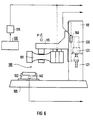
- an ultrasound sonotrode 101 is attached as an active welding tool to the displaceable slide 115 of a stand 110.
- the stand 110 stands on a base plate 105 with an anvil 102 as a receiving tool for the joining parts.
- a three-phase motor 120 with a gear 121 is arranged in the stator 110, with which the motor movement is transmitted to the carriage 115.
- the rotational movement of the motor 120 or the lowering movement of the sonotrode 101 achieved thereby can be predetermined with a tachometer generator 125.
- the sonotrode 101 with ultrasound transducer is assigned a generator 130 with a downstream control device 135, with which the ultrasound activation of the sonotrode and the motor drive are controlled in the same way.
- the welding press 100 can furthermore have a force transducer 140, which is advantageously arranged in the anvil 102. If necessary, the force building up in the parts to be joined can thus be detected.
- a displacement measuring system 150 can also be present, with which the actual deformation path of the parts to be joined is determined.
- the ultrasound activation and the lowering speed of the sonotrode 101 can be set with regard to the start and end.
- the lowering speed of the sonotrode can also be specified as a variable time profile. This time profile is set so that a desired Force course is realized.
- the lowering speed of the sonotrode is initially kept low starting with the touch of the workpieces and is only increased when the workpieces are plasticized.
- the Graph 200 indicates the lowering speed of the sonotrode over a complete welding cycle, which can be divided into individual significant areas.
- the movement of sonotrode 101 runs at a free speed of, for example, 50 mm / s. From point A onwards, the lowering speed is significantly damped and runs at a low speed in area 12.
- the ultrasound is activated at point B, so that at point C, when the sonotrode hits the surface of the wire, an increase in force occurs because the workpieces are still cold.
- the lowering speed of the sonotrode is constantly preselected in accordance with lines 201 to 204 in various variants.
- the value of the speed is determined depending on the dimensions and / or the surface properties of the workpieces. In particular, a coating of the workpieces can thus also be taken into account.
- a copper wire with a diameter of ⁇ 100 ⁇ m will, for example, be welded to the sonotrode 101 at the lowest lowering speed 201.
- the lowering speed can be increased, which is easily possible due to the motor drive for the welding press.
- the lowering speed of the sonotrode 101 according to the line 205 is initially selected to be slow for a longer period when the sonotrode is activated. This means that time is given to remove the varnish from the wire surface or to remove oxides and other contaminants. Only after all non-metallic components have been removed from the joining surface, the working speed is increased in stages and a predetermined deformation program is now carried out.
- the cross section of the wire changes in a desired manner and the welded connection according to FIGS. 4 and 5 is produced by the ultrasound-activated friction process of the joining parts. After the ultrasound has been switched off, the sonotrode 101 is then moved back.
- the lowering speed can be changed continuously from lower to higher values instead of gradually.
- the lowering speed of the sonotrode is changed along line 206 in the manner of an e-profile.
- Other functional dependencies are also possible.
Landscapes
- Engineering & Computer Science (AREA)
- Mechanical Engineering (AREA)
- Manufacturing & Machinery (AREA)
- Pressure Welding/Diffusion-Bonding (AREA)
Claims (7)
- Procédé pour souder des fils métalliques (6) et/ou des torons isolés par du vernis sur des supports (5) métalliques par ultrasons, dans lequel, par application d'une force d'une part, et par action des ultrasons d'une sonotrode (1/101) d'autre part, il est obtenu une liaison de matière à matière par déformation (6', 6'') de la matière d'au moins les fils (6) et/ou les torons, qui est donnée par la durée de soudage, en fonction d'une vitesse (v), qui peut être prescrite, d'abaissement de la sonotrode (1/101), la vitesse (v) d'abaissement étant réglable ou programmable, caractérisé en ce que les paramètres de réglage ou de régulation de la vitesse (v) d'abaissement de la sonotrode (1/101) sont les dimensions et/ou la constitution des surfaces des fils (6) et/ou des torons ou de leur revêtement (7), la vitesse (v) d'abaissement étant réglée à une valeur constante pendant la déformation de la matière où sa variation (205, 206) de valeurs petites à des valeurs grandes étant préprogrammée.
- Procédé suivant la revendication 1, caractérisé en ce que la vitesse (v) d'abaissement de la sonotrode est augmentée par paliers (205) (figure 8).
- Procédé suivant la revendication 1, caractérisé en ce que la vitesse (v) d'abaissement est donnée sous la forme d'un profil (206) en fonction du temps (figure 9).
- Dispositif pour la mise en oeuvre du procédé suivant la revendication 1 ou l'une des revendications 2 ou 3, comprenant un système d'entraînement d'une presse (100) de soudage à ultrasons, qui se compose d'une sonotrode (101) susceptible d'être mise en action par un générateur (130) et d'être abaissée, et d'une enclume (102) fixe de réception du support (5) métallique, le système d'entraînement étant un dispositif d'entraînement (120) à moteur, réglable ou programmable, caractérisé en ce qu'en aval du générateur (130) de la sonotrode (101) est monté un appareil (135) de commande, par lequel est effectué de la même façon la mise en action des ultrasons de la sonotrode (101) en fonction du temps et la régulation ou la programmation du dispositif d'entraînement (120) à moteur, et en ce qu'il est prévu des moyens destinés à régler ou à réguler la vitesse (v) d'abaissement de la sonotrode (1/101) en fonction des dimensions et/ou de la constitution des surfaces des fils (6) et/ou des torons ou de leur revêtement (7), ces moyens donnant une vitesse (v) d'abaissement constante (201 à 204) ou préprogrammant sa variation (205, 206) de valeurs petites à des valeurs grandes.
- Dispositif suivant la revendication 4, caractérisé en ce que le dispositif d'entraînement (120) à moteur programmable est constitué d'un moteur triphasé (121) à génératrice tachymétrique (125).
- Dispositif suivant la revendication 4, caractérisé en ce que la presse (100) de soudage comporte un capteur de déplacement (150).
- Dispositif suivant la revendication 4, caractérisé en ce que la presse (100) de soudage comporte un capteur de force (140).
Priority Applications (2)
| Application Number | Priority Date | Filing Date | Title |
|---|---|---|---|
| EP19890118618 EP0421018B1 (fr) | 1989-10-06 | 1989-10-06 | Méthode et dispositif de soudage de pièces métalliques par ultrasons |
| DE89118618T DE58907246D1 (de) | 1989-10-06 | 1989-10-06 | Verfahren und Vorrichtung zum Schweissen von metallischen Werkstücken durch Ultraschall. |
Applications Claiming Priority (1)
| Application Number | Priority Date | Filing Date | Title |
|---|---|---|---|
| EP19890118618 EP0421018B1 (fr) | 1989-10-06 | 1989-10-06 | Méthode et dispositif de soudage de pièces métalliques par ultrasons |
Publications (2)
| Publication Number | Publication Date |
|---|---|
| EP0421018A1 EP0421018A1 (fr) | 1991-04-10 |
| EP0421018B1 true EP0421018B1 (fr) | 1994-03-16 |
Family
ID=8201990
Family Applications (1)
| Application Number | Title | Priority Date | Filing Date |
|---|---|---|---|
| EP19890118618 Expired - Lifetime EP0421018B1 (fr) | 1989-10-06 | 1989-10-06 | Méthode et dispositif de soudage de pièces métalliques par ultrasons |
Country Status (2)
| Country | Link |
|---|---|
| EP (1) | EP0421018B1 (fr) |
| DE (1) | DE58907246D1 (fr) |
Cited By (5)
| Publication number | Priority date | Publication date | Assignee | Title |
|---|---|---|---|---|
| US7491280B2 (en) | 2003-04-30 | 2009-02-17 | Schunk Ultraschalltechnik Gmbh | Systems and methods for welding of parts |
| US9688017B2 (en) | 2013-05-14 | 2017-06-27 | Dukan IAS, LLC | Vibration welders with high frequency vibration, position motion control, and delayed weld motion |
| US9849627B2 (en) | 2006-05-08 | 2017-12-26 | Dukane Ias, Llc | Ultrasonic press using servo motor with delayed motion |
| US9849628B2 (en) | 2006-05-08 | 2017-12-26 | Dukane Ias, Llc | Ultrasonic welding method using delayed motion of welding stack |
| DE102022128873A1 (de) * | 2022-11-01 | 2024-05-02 | Albert-Ludwigs-Universität Freiburg, Körperschaft des öffentlichen Rechts | Ultraschallschweißverfahren mit Fügepartnerrückmeldung sowie Vorrichtung hierfür |
Families Citing this family (9)
| Publication number | Priority date | Publication date | Assignee | Title |
|---|---|---|---|---|
| EP0701876B1 (fr) * | 1994-08-22 | 1998-04-15 | SCHUNK Ultraschalltechnik GmbH | Méthode de compactage et de soudage de fils conducteurs |
| DE19541976A1 (de) * | 1995-11-10 | 1997-05-15 | Ego Elektro Blanc & Fischer | Elektrische Schaltung |
| DE19605038A1 (de) * | 1996-02-12 | 1997-08-14 | Daimler Benz Ag | Verfahren zum Bonden von Isolierdraht und Vorrichtung zur Durchführung des Verfahrens |
| JP3447982B2 (ja) * | 1999-06-16 | 2003-09-16 | 株式会社アルテクス | 超音波振動接合装置 |
| KR20110119304A (ko) * | 2010-04-27 | 2011-11-02 | 삼성엘이디 주식회사 | 본딩면의 바운싱 모니터링 장치, 이를 구비한 와이어 본딩 장치 및 본딩면의 바운싱 모니터링 방법 |
| US8245748B2 (en) | 2010-07-14 | 2012-08-21 | Dukane Corporation | Vibration welding system |
| DE102013212331A1 (de) | 2013-04-04 | 2014-10-09 | Telsonic Holding Ag | Verfahren zum Verbinden eines Rohrkabelschuhs mit einer aus Aluminium hergestellten Litze |
| DE102013106349A1 (de) * | 2013-05-13 | 2014-11-13 | Schunk Sonosystems Gmbh | Verfahren zum Ermitteln des Verdichtungsgrades eines Knotens |
| US10549481B1 (en) | 2018-12-21 | 2020-02-04 | Dukane Ias, Llc | Systems and methods for low initial weld speed in ultrasonic welding |
Family Cites Families (2)
| Publication number | Priority date | Publication date | Assignee | Title |
|---|---|---|---|---|
| FR2302172A1 (fr) * | 1975-02-27 | 1976-09-24 | Podselver Michel | Perfectionnements aux appareils de soudage avec pression |
| US4631685A (en) * | 1984-12-07 | 1986-12-23 | General Motors Corporation | Method and apparatus for ultrasonic plastic forming and joining |
-
1989
- 1989-10-06 DE DE89118618T patent/DE58907246D1/de not_active Expired - Fee Related
- 1989-10-06 EP EP19890118618 patent/EP0421018B1/fr not_active Expired - Lifetime
Cited By (6)
| Publication number | Priority date | Publication date | Assignee | Title |
|---|---|---|---|---|
| US7491280B2 (en) | 2003-04-30 | 2009-02-17 | Schunk Ultraschalltechnik Gmbh | Systems and methods for welding of parts |
| US9849627B2 (en) | 2006-05-08 | 2017-12-26 | Dukane Ias, Llc | Ultrasonic press using servo motor with delayed motion |
| US9849628B2 (en) | 2006-05-08 | 2017-12-26 | Dukane Ias, Llc | Ultrasonic welding method using delayed motion of welding stack |
| US9914263B2 (en) | 2006-05-08 | 2018-03-13 | Dukane Ias, Llc | Ultrasonic press with automatic speed changes in advancing movement of welding stack |
| US9688017B2 (en) | 2013-05-14 | 2017-06-27 | Dukan IAS, LLC | Vibration welders with high frequency vibration, position motion control, and delayed weld motion |
| DE102022128873A1 (de) * | 2022-11-01 | 2024-05-02 | Albert-Ludwigs-Universität Freiburg, Körperschaft des öffentlichen Rechts | Ultraschallschweißverfahren mit Fügepartnerrückmeldung sowie Vorrichtung hierfür |
Also Published As
| Publication number | Publication date |
|---|---|
| EP0421018A1 (fr) | 1991-04-10 |
| DE58907246D1 (de) | 1994-04-21 |
Similar Documents
| Publication | Publication Date | Title |
|---|---|---|
| EP0421019B1 (fr) | Méthode et dispositif de jointure d'éléments en matière plastique par ultrasons | |
| EP0421018B1 (fr) | Méthode et dispositif de soudage de pièces métalliques par ultrasons | |
| DE60312793T2 (de) | Verfahren und Verwendung einer Vorrichtung zum Reibrührschweissen | |
| EP3119584B1 (fr) | Dispositif et méthode de mise en place d'un élément à mettre en place dans une pièce | |
| EP2289659B1 (fr) | Dispositif de liaison par friction d'au moins deux plaques au moyen d'un élément de liaison avec un système de mesure de l'effort appliqué et du déplacement durant la liaison | |
| DE102009023853B4 (de) | Widerstandsschweißverfahren und geschweißte Struktur | |
| EP1776205B1 (fr) | Procede de soudage par friction d'elements constitutifs | |
| DE60206893T2 (de) | Drehendes reibungschweissverfahren und vorrichtung | |
| EP0340671B1 (fr) | Procédé et appareil pour la commande des paramètres d'une machine de soudage par friction | |
| DE3037505C2 (fr) | ||
| DE19523240C1 (de) | Verfahren und Vorrichtung zum Reibschweißen von Werkstücken | |
| DE4317621C1 (de) | Vorrichtung zum Bearbeiten eines Bauteils mittels Ultraschall und Verfahren | |
| EP0759332B1 (fr) | Machine à cintrer des tubes à commande CNC | |
| WO2020048561A1 (fr) | Procédé pour former un contact électrique d'un bloc de batteries | |
| EP3259094A1 (fr) | Procédé et dispositif de soudage par friction | |
| DE102009009178A1 (de) | Vorrichtung zum Bearbeiten von Sägezähnen eines Sägeblattes | |
| WO2000018528A1 (fr) | Procede et dispositif pour assembler des elements sous forme de plaques qui se chevauchent | |
| DE278185T1 (de) | Numerisch gesteuerte widerstandsschweissmaschine und bolzen- und mutter-system oder analogisches | |
| WO2023272318A1 (fr) | Procédé permettant de raccorder des composants disposés les uns au-dessus des autres, composant composite et dispositif permettant de mettre en œuvre un procédé correspondant | |
| DE19902357A1 (de) | Verfahren und Vorrichtung zum Führen eines Reibschweißprozesses | |
| EP3546084B1 (fr) | Procédé de liaison d'au moins deux composants au moyen d'un dispositif de rivetage et dispositif de rivetage | |
| EP4108427B1 (fr) | Procédé de commande d'un processus de traitement | |
| EP3357620A1 (fr) | Procédé et dispositif destinés au soudage par ultrasons d'éléments à assembler, en particulier des conducteurs électriques | |
| EP4065349B1 (fr) | Procédé de traitement ultrasonore | |
| DE102004004194A1 (de) | Verfahren zum Schneiden und Kleben und zugehörige Vorrichtung |
Legal Events
| Date | Code | Title | Description |
|---|---|---|---|
| PUAI | Public reference made under article 153(3) epc to a published international application that has entered the european phase |
Free format text: ORIGINAL CODE: 0009012 |
|
| 17P | Request for examination filed |
Effective date: 19901009 |
|
| AK | Designated contracting states |
Kind code of ref document: A1 Designated state(s): CH DE FR GB LI NL |
|
| 17Q | First examination report despatched |
Effective date: 19920131 |
|
| GRAA | (expected) grant |
Free format text: ORIGINAL CODE: 0009210 |
|
| AK | Designated contracting states |
Kind code of ref document: B1 Designated state(s): CH DE FR GB LI NL |
|
| REF | Corresponds to: |
Ref document number: 58907246 Country of ref document: DE Date of ref document: 19940421 |
|
| GBT | Gb: translation of ep patent filed (gb section 77(6)(a)/1977) |
Effective date: 19940624 |
|
| ET | Fr: translation filed | ||
| PLBE | No opposition filed within time limit |
Free format text: ORIGINAL CODE: 0009261 |
|
| STAA | Information on the status of an ep patent application or granted ep patent |
Free format text: STATUS: NO OPPOSITION FILED WITHIN TIME LIMIT |
|
| 26N | No opposition filed | ||
| REG | Reference to a national code |
Ref country code: GB Ref legal event code: 732E |
|
| NLS | Nl: assignments of ep-patents |
Owner name: HELMUT MOLL |
|
| PGFP | Annual fee paid to national office [announced via postgrant information from national office to epo] |
Ref country code: GB Payment date: 19981023 Year of fee payment: 10 |
|
| PGFP | Annual fee paid to national office [announced via postgrant information from national office to epo] |
Ref country code: NL Payment date: 19981030 Year of fee payment: 10 |
|
| PGFP | Annual fee paid to national office [announced via postgrant information from national office to epo] |
Ref country code: FR Payment date: 19981116 Year of fee payment: 10 |
|
| REG | Reference to a national code |
Ref country code: FR Ref legal event code: TP |
|
| PGFP | Annual fee paid to national office [announced via postgrant information from national office to epo] |
Ref country code: DE Payment date: 19981130 Year of fee payment: 10 |
|
| PGFP | Annual fee paid to national office [announced via postgrant information from national office to epo] |
Ref country code: CH Payment date: 19981210 Year of fee payment: 10 |
|
| REG | Reference to a national code |
Ref country code: CH Ref legal event code: PUE Owner name: SIEMENS AKTIENGESELLSCHAFT TRANSFER- HELMUT MOLL Ref country code: CH Ref legal event code: NV Representative=s name: ISLER & PEDRAZZINI AG |
|
| PG25 | Lapsed in a contracting state [announced via postgrant information from national office to epo] |
Ref country code: GB Free format text: LAPSE BECAUSE OF NON-PAYMENT OF DUE FEES Effective date: 19991006 |
|
| PG25 | Lapsed in a contracting state [announced via postgrant information from national office to epo] |
Ref country code: LI Free format text: LAPSE BECAUSE OF NON-PAYMENT OF DUE FEES Effective date: 19991031 Ref country code: CH Free format text: LAPSE BECAUSE OF NON-PAYMENT OF DUE FEES Effective date: 19991031 |
|
| PG25 | Lapsed in a contracting state [announced via postgrant information from national office to epo] |
Ref country code: NL Free format text: LAPSE BECAUSE OF NON-PAYMENT OF DUE FEES Effective date: 20000501 |
|
| GBPC | Gb: european patent ceased through non-payment of renewal fee |
Effective date: 19991006 |
|
| REG | Reference to a national code |
Ref country code: CH Ref legal event code: PL |
|
| PG25 | Lapsed in a contracting state [announced via postgrant information from national office to epo] |
Ref country code: FR Free format text: LAPSE BECAUSE OF NON-PAYMENT OF DUE FEES Effective date: 20000630 |
|
| NLV4 | Nl: lapsed or anulled due to non-payment of the annual fee |
Effective date: 20000501 |
|
| PG25 | Lapsed in a contracting state [announced via postgrant information from national office to epo] |
Ref country code: DE Free format text: LAPSE BECAUSE OF NON-PAYMENT OF DUE FEES Effective date: 20000801 |
|
| REG | Reference to a national code |
Ref country code: FR Ref legal event code: ST |