EP0701876B1 - Méthode de compactage et de soudage de fils conducteurs - Google Patents
Méthode de compactage et de soudage de fils conducteurs Download PDFInfo
- Publication number
- EP0701876B1 EP0701876B1 EP95112986A EP95112986A EP0701876B1 EP 0701876 B1 EP0701876 B1 EP 0701876B1 EP 95112986 A EP95112986 A EP 95112986A EP 95112986 A EP95112986 A EP 95112986A EP 0701876 B1 EP0701876 B1 EP 0701876B1
- Authority
- EP
- European Patent Office
- Prior art keywords
- value
- welding
- values
- compaction
- measured
- Prior art date
- Legal status (The legal status is an assumption and is not a legal conclusion. Google has not performed a legal analysis and makes no representation as to the accuracy of the status listed.)
- Expired - Lifetime
Links
- 238000003466 welding Methods 0.000 title claims description 85
- 238000000034 method Methods 0.000 title claims description 39
- 238000004519 manufacturing process Methods 0.000 claims description 31
- 239000004020 conductor Substances 0.000 claims description 29
- 238000005056 compaction Methods 0.000 claims description 24
- 239000000463 material Substances 0.000 claims description 12
- 238000002604 ultrasonography Methods 0.000 claims description 11
- 229920003023 plastic Polymers 0.000 claims description 3
- 239000004033 plastic Substances 0.000 claims description 3
- 239000000843 powder Substances 0.000 claims description 3
- 238000007906 compression Methods 0.000 description 27
- 230000006835 compression Effects 0.000 description 26
- 239000000047 product Substances 0.000 description 6
- 238000005516 engineering process Methods 0.000 description 2
- 230000007774 longterm Effects 0.000 description 2
- 238000005259 measurement Methods 0.000 description 2
- 230000036278 prepulse Effects 0.000 description 2
- 238000012552 review Methods 0.000 description 2
- 238000009210 therapy by ultrasound Methods 0.000 description 2
- 230000006978 adaptation Effects 0.000 description 1
- 238000004364 calculation method Methods 0.000 description 1
- 239000007795 chemical reaction product Substances 0.000 description 1
- 238000010276 construction Methods 0.000 description 1
- 238000010586 diagram Methods 0.000 description 1
- 239000006185 dispersion Substances 0.000 description 1
- 238000011156 evaluation Methods 0.000 description 1
- 230000002349 favourable effect Effects 0.000 description 1
- 238000001208 nuclear magnetic resonance pulse sequence Methods 0.000 description 1
- 230000003287 optical effect Effects 0.000 description 1
- 230000003449 preventive effect Effects 0.000 description 1
- 238000003860 storage Methods 0.000 description 1
- 210000004243 sweat Anatomy 0.000 description 1
- 238000012360 testing method Methods 0.000 description 1
Images

Classifications
-
- B—PERFORMING OPERATIONS; TRANSPORTING
- B29—WORKING OF PLASTICS; WORKING OF SUBSTANCES IN A PLASTIC STATE IN GENERAL
- B29C—SHAPING OR JOINING OF PLASTICS; SHAPING OF MATERIAL IN A PLASTIC STATE, NOT OTHERWISE PROVIDED FOR; AFTER-TREATMENT OF THE SHAPED PRODUCTS, e.g. REPAIRING
- B29C65/00—Joining or sealing of preformed parts, e.g. welding of plastics materials; Apparatus therefor
- B29C65/02—Joining or sealing of preformed parts, e.g. welding of plastics materials; Apparatus therefor by heating, with or without pressure
- B29C65/08—Joining or sealing of preformed parts, e.g. welding of plastics materials; Apparatus therefor by heating, with or without pressure using ultrasonic vibrations
-
- B—PERFORMING OPERATIONS; TRANSPORTING
- B23—MACHINE TOOLS; METAL-WORKING NOT OTHERWISE PROVIDED FOR
- B23K—SOLDERING OR UNSOLDERING; WELDING; CLADDING OR PLATING BY SOLDERING OR WELDING; CUTTING BY APPLYING HEAT LOCALLY, e.g. FLAME CUTTING; WORKING BY LASER BEAM
- B23K20/00—Non-electric welding by applying impact or other pressure, with or without the application of heat, e.g. cladding or plating
- B23K20/10—Non-electric welding by applying impact or other pressure, with or without the application of heat, e.g. cladding or plating making use of vibrations, e.g. ultrasonic welding
-
- B—PERFORMING OPERATIONS; TRANSPORTING
- B29—WORKING OF PLASTICS; WORKING OF SUBSTANCES IN A PLASTIC STATE IN GENERAL
- B29C—SHAPING OR JOINING OF PLASTICS; SHAPING OF MATERIAL IN A PLASTIC STATE, NOT OTHERWISE PROVIDED FOR; AFTER-TREATMENT OF THE SHAPED PRODUCTS, e.g. REPAIRING
- B29C66/00—General aspects of processes or apparatus for joining preformed parts
- B29C66/90—Measuring or controlling the joining process
- B29C66/92—Measuring or controlling the joining process by measuring or controlling the pressure, the force, the mechanical power or the displacement of the joining tools
- B29C66/922—Measuring or controlling the joining process by measuring or controlling the pressure, the force, the mechanical power or the displacement of the joining tools by measuring the pressure, the force, the mechanical power or the displacement of the joining tools
- B29C66/9221—Measuring or controlling the joining process by measuring or controlling the pressure, the force, the mechanical power or the displacement of the joining tools by measuring the pressure, the force, the mechanical power or the displacement of the joining tools by measuring the pressure, the force or the mechanical power
-
- B—PERFORMING OPERATIONS; TRANSPORTING
- B23—MACHINE TOOLS; METAL-WORKING NOT OTHERWISE PROVIDED FOR
- B23K—SOLDERING OR UNSOLDERING; WELDING; CLADDING OR PLATING BY SOLDERING OR WELDING; CUTTING BY APPLYING HEAT LOCALLY, e.g. FLAME CUTTING; WORKING BY LASER BEAM
- B23K2101/00—Articles made by soldering, welding or cutting
- B23K2101/32—Wires
-
- B—PERFORMING OPERATIONS; TRANSPORTING
- B29—WORKING OF PLASTICS; WORKING OF SUBSTANCES IN A PLASTIC STATE IN GENERAL
- B29C—SHAPING OR JOINING OF PLASTICS; SHAPING OF MATERIAL IN A PLASTIC STATE, NOT OTHERWISE PROVIDED FOR; AFTER-TREATMENT OF THE SHAPED PRODUCTS, e.g. REPAIRING
- B29C66/00—General aspects of processes or apparatus for joining preformed parts
- B29C66/80—General aspects of machine operations or constructions and parts thereof
- B29C66/82—Pressure application arrangements, e.g. transmission or actuating mechanisms for joining tools or clamps
- B29C66/824—Actuating mechanisms
- B29C66/8242—Pneumatic or hydraulic drives
-
- B—PERFORMING OPERATIONS; TRANSPORTING
- B29—WORKING OF PLASTICS; WORKING OF SUBSTANCES IN A PLASTIC STATE IN GENERAL
- B29C—SHAPING OR JOINING OF PLASTICS; SHAPING OF MATERIAL IN A PLASTIC STATE, NOT OTHERWISE PROVIDED FOR; AFTER-TREATMENT OF THE SHAPED PRODUCTS, e.g. REPAIRING
- B29C66/00—General aspects of processes or apparatus for joining preformed parts
- B29C66/90—Measuring or controlling the joining process
- B29C66/92—Measuring or controlling the joining process by measuring or controlling the pressure, the force, the mechanical power or the displacement of the joining tools
- B29C66/922—Measuring or controlling the joining process by measuring or controlling the pressure, the force, the mechanical power or the displacement of the joining tools by measuring the pressure, the force, the mechanical power or the displacement of the joining tools
- B29C66/9221—Measuring or controlling the joining process by measuring or controlling the pressure, the force, the mechanical power or the displacement of the joining tools by measuring the pressure, the force, the mechanical power or the displacement of the joining tools by measuring the pressure, the force or the mechanical power
- B29C66/92211—Measuring or controlling the joining process by measuring or controlling the pressure, the force, the mechanical power or the displacement of the joining tools by measuring the pressure, the force, the mechanical power or the displacement of the joining tools by measuring the pressure, the force or the mechanical power with special measurement means or methods
-
- B—PERFORMING OPERATIONS; TRANSPORTING
- B29—WORKING OF PLASTICS; WORKING OF SUBSTANCES IN A PLASTIC STATE IN GENERAL
- B29C—SHAPING OR JOINING OF PLASTICS; SHAPING OF MATERIAL IN A PLASTIC STATE, NOT OTHERWISE PROVIDED FOR; AFTER-TREATMENT OF THE SHAPED PRODUCTS, e.g. REPAIRING
- B29C66/00—General aspects of processes or apparatus for joining preformed parts
- B29C66/90—Measuring or controlling the joining process
- B29C66/92—Measuring or controlling the joining process by measuring or controlling the pressure, the force, the mechanical power or the displacement of the joining tools
- B29C66/924—Measuring or controlling the joining process by measuring or controlling the pressure, the force, the mechanical power or the displacement of the joining tools by controlling or regulating the pressure, the force, the mechanical power or the displacement of the joining tools
- B29C66/9241—Measuring or controlling the joining process by measuring or controlling the pressure, the force, the mechanical power or the displacement of the joining tools by controlling or regulating the pressure, the force, the mechanical power or the displacement of the joining tools by controlling or regulating the pressure, the force or the mechanical power
-
- B—PERFORMING OPERATIONS; TRANSPORTING
- B29—WORKING OF PLASTICS; WORKING OF SUBSTANCES IN A PLASTIC STATE IN GENERAL
- B29C—SHAPING OR JOINING OF PLASTICS; SHAPING OF MATERIAL IN A PLASTIC STATE, NOT OTHERWISE PROVIDED FOR; AFTER-TREATMENT OF THE SHAPED PRODUCTS, e.g. REPAIRING
- B29C66/00—General aspects of processes or apparatus for joining preformed parts
- B29C66/90—Measuring or controlling the joining process
- B29C66/94—Measuring or controlling the joining process by measuring or controlling the time
-
- B—PERFORMING OPERATIONS; TRANSPORTING
- B29—WORKING OF PLASTICS; WORKING OF SUBSTANCES IN A PLASTIC STATE IN GENERAL
- B29C—SHAPING OR JOINING OF PLASTICS; SHAPING OF MATERIAL IN A PLASTIC STATE, NOT OTHERWISE PROVIDED FOR; AFTER-TREATMENT OF THE SHAPED PRODUCTS, e.g. REPAIRING
- B29C66/00—General aspects of processes or apparatus for joining preformed parts
- B29C66/90—Measuring or controlling the joining process
- B29C66/95—Measuring or controlling the joining process by measuring or controlling specific variables not covered by groups B29C66/91 - B29C66/94
- B29C66/959—Measuring or controlling the joining process by measuring or controlling specific variables not covered by groups B29C66/91 - B29C66/94 characterised by specific values or ranges of said specific variables
- B29C66/9592—Measuring or controlling the joining process by measuring or controlling specific variables not covered by groups B29C66/91 - B29C66/94 characterised by specific values or ranges of said specific variables in explicit relation to another variable, e.g. X-Y diagrams
Definitions
- the invention relates to a method for compacting and subsequent Welding of electrical conductors, in particular for the production of through or End nodes of strands using ultrasound in a compression space that can be adapted to the conductor, whereby the conductors to be welded are first compacted and then be welded.
- ultrasonic welding devices used the sonotrodes for the generation of Have ultrasonic vibrations.
- a section of the respective sonotrode forms one first lateral boundary surface of a z.
- the other boundary surfaces of the compression room can be sections of a multi-part counter electrode.
- Examples of ultrasonic welding devices are under the names RK 2000 or Minic Automatic the Schunk Ultrasonic Technology GmbH, Wettenberg, Federal Republic of Germany, offered equipment.
- the invention is therefore based on the problem of a method as described in the introduction Kind to develop in such a way that from the welded for the generation electrical conductors operations obtained parameters that decisive for the properties of the manufactured products are automatically ensured can be that the welded products within narrower allowable Manufacturing tolerances lie.
- the problem is solved according to the invention in a method of the type described in the introduction solved in that after the compaction of the ladder the size of the Compacting value measured or determined from measured values and at least with a predetermined upper and a lower, related to a setpoint Limit value is compared to a value that is outside of the limit values included area, the weld is not carried out and at a Value that is within the range of the limits, the value with values determined in previous operations to a new setpoint for the Checking subsequent compacting operations is charged and the welding is carried out and / or that at or after completion of the weld existing value of at least one parameter relevant to the welding process measured or determined from measured values and at least with an upper and lower, a limit value related to a target value is compared and that with an outside an error is displayed in the value within the range covered by the limit values and if the value is within this range, it is the same with previous values Operations specific values to a new setpoint for review subsequent welding operations is charged.
- the conductors are during the compaction subjected to ultrasound.
- the strength of this ultrasound exposure is lower than the thickness necessary for welding the conductors.
- the additional ultrasound treatment during compaction causes the conductor to compact more become what is particularly favorable for the subsequent measurement and welding.
- the ultrasound treatment of the conductors during compacting has its own inventive content, since it also without the above-described setpoint adjustment leads to an improvement in the subsequent welding.
- the cross section of the Compression room can be selected by the conductors at or after termination of the welding process is taken or filled out. In particular, however select the height or the width of the compression space as the decisive parameter.
- the fixed limit values are also referred to below as external limit values when setting up the ultrasonic welding device provided for carrying out the method determined and saved.
- the limit values formed with the help of the setpoints The following are also referred to as internal limit values, which allow slight deviations between successive manufacturing processes.
- the method according to the invention enables even small ones Detect errors safely.
- the setpoints are preferably used as arithmetic mean values from several values previous manufacturing steps calculated.
- the number of to determine the Measured values to be used as mean values can be between a few and tens of values.
- the one immediately following the setting up of the ultrasonic welding device Manufacturing step, the setpoints determined during setup are used.
- the teaching according to the invention is also based on a method for welding and, if appropriate previously compacting material such as plastic material and powder by means of Ultrasound can be used in a compression space that accommodates the material characterized in that an existing at or after completion of the weld Value of at least one parameter relevant to the welding process measured or from Measured values determined and at least with an upper and lower, to a target value related limit value is compared and that at an outside of the by the Limit values included range an error is displayed and at a value within this range with this in previous operations certain values to a new setpoint for checking subsequent ones Welding operations are charged and / or that after the compaction of the Measured or measured a value indicating the size of the compaction Measured values determined and at least with a predetermined upper and a lower limit value related to a target value is compared, that at a value which is outside the range enclosed by the limit values, the weld not executed and at a value that is within the limits included range, the value determined with previous operations Values for a new set
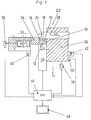
- Fig. 1 is a section of an ultrasonic welding device for welding electrical Conductor shown, as far as a compression space adjustable to the conductor to be welded (10) is affected.
- the ultrasonic welding device itself always correspond to a construction that corresponds to the RK 2000 or Minic Automatic from Schunk Ultrasound Technology GmbH, Wettenberg.
- the compression chamber (10) has a rectangular cross section in the exemplary embodiment and is open at the end to close the conductors to be welded through them to lead. Compression areas with other cross sections are of course also possible, especially with a trapezoidal cross-section.
- the compression space (10) is laterally by boundary surfaces (12), (14), (16) and (18) enclosed on the one hand by a section of a sonotrode (20) and on the other hand be limited by a multi-part counter electrode (22) such as anvil.
- the multi-part counter electrode (22) comprises a slide (24) which along the the boundary surface (12) provided for the sonotrode (12) is displaceable and forms the lateral boundary surface (14).
- the direction of movement of the slider (24) is indicated by the arrow (S2).
- the slide (24) is opposite second part (26) of the counter electrode (22) arranged parallel to the boundary surface (14), that is to say displaceable perpendicular to the sonotrode surface (12) (S1).
- the second part (26) slidably takes a section (28) to be called a nose on, which is movable according to the arrow (S3) parallel to the surface (12).
- the compression space (10) is used to compact the inserted conductor, that is to say Pre-compaction, set to a previously defined height-width ratio. This is in Fig. 1 by different rectangles drawn in the compression space Symbolizes greatness.
- the slide (24) is provided with a drive (36), in particular a pneumatic or hydraulic drive, connected by the slide (24) in the direction of the arrow S2 and vice versa is movable.
- the part (26) of the counter electrode (22) is with a Drive (38) connected, which is also preferably a pneumatic or hydraulic Drive can be formed.
- the part (26) can be displaced in the direction of the arrow S1 and vice versa by means of the drive (38).
- the slide (24) is also connected to a position sensor (40) which the position of the slide (24) can be measured with respect to a rest position. That too Part (26) is connected to a position sensor (42) with which the position of the part (26) can be determined in relation to a rest position.
- a control device (46), e.g. a programmable logic controller is available with the Position sensors (40), (42), the ultrasound set sonotrode (20) and not Connected controls for the drives (36), (38) connected. To the A monitor (48) is connected to the control device (46).
- the height (h) and / or the width (b) of the precompression chamber (10) is determined by means of at least one position sensor, in the exemplary embodiment of the position sensors (40), (42) generated measured values and evaluated by the control device (46).
- Different cross sections or different heights or widths of the compression area (10) various parameters are associated with the ultrasonic welding device for welding the conductors. It is a matter of Welding parameters such as welding energy, welding amplitude, welding time and welding pressure.
- a force sensor (50) can also be connected to the part (26), with which the force sensor in the compression space (10) inserted conductor by means of the part (26) exerted force is measured.
- the force sensor is also connected to the control unit (46).
- indirect measurement can also be carried out by pressure control.
- the in the compression space (10) inserted conductor compacted by moving the slide (24) and the part (22) be that the cross section of the precompression chamber (10) is reduced.
- Forces for the setting of the cross section are from the control unit (46) to the drives (36), (38) triggering outgoing signals, the respective cross-section being established of the precompression chamber by means of the measuring range generated by the position sensors (40), (42) is determined by the control unit (46).
- the cross section or the height or the width of the precompression chamber (10) at the end or after completion of the pre-compression is therefore a measure of the degree of Pre-compression, i.e. the geometry of the pre-compression space can be used as a pre-compression dimension or compacting dimension can be used or evaluated. Because e.g. only that Width (b) and / or the height (h) of the precompression chamber (10) can be changed the cross-section can be determined quickly and easily.
- the force exerted on the conductor can also be can be used as a precompression measure.
- the cross-section is basically only the height or the width of the pre-compression space changed again, the one at or after completion the existing cross-section of the weld is a measure of the quality of the weld the leader is.
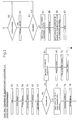
- step (52) which is labeled "Start” in FIG. 2, the ultrasonic welding device set in motion. Then in a step (54) certain strand combination inserted in the compression chamber (10). Subsequently the manufacturing process for the welded conductors is started in a step (56). Then in a step (58) the compression chamber (10) is closed by the Slider (24) and the part (26) in directions indicated by the arrows (S2) and (S1) are designated, driven or moved. In Fig. 2, step (58) is with "Close tools" called.
- step (58) or thereafter an ultrasound pulse or sequence generated to compact the conductors more. This actually takes place Meaning an equalization of the compacting (step (60)).
- step (62) After compacting in a subsequent step (62) the compacting dimension from the Geometry of the compression space by knowing the width and / or height or another specific size is determined.
- a step follows (64), in which the determined compacting dimension first with an upper and a lower "outer" limit is compared.
- the upper and lower outer limits are set when setting up the ultrasonic welding device certainly.
- the limits set the external limits for the Press dimensions fixed.
- the compacting dimension with an upper and lower “inner” limit compared.
- the upper and lower “inner” limit will be from the nominal value of the press size plus a first tolerance value and minus a second tolerance value is determined.
- the tolerance values do not have to be the same be great.
- a step (66) follows in which an optical and / or acoustic error message is generated, which leads to a step (68) in which the tools are opened so that the manufacturing process is no longer is continued.
- the conductors can be removed from the ultrasonic welding device will.
- Step (70) is written into a statistic which is stored in a file in the control unit (46) is available.
- the error is acknowledged or when the external one is exceeded Limits of the process are checked and corrected if necessary.
- the compacting dimension is within the limits included Ranges, then follows a method step (74), in which, from compacting dimensions measured and stored in previous n-manufacturing processes or steps and the just determined value a new setpoint for the compacting dimension is determined.
- the compacting dimension is straight ongoing manufacturing process is therefore included.
- the setpoint is e.g. as an arithmetic Average value for testing the next welded manufacturing process Head determined.
- the number n is e.g. between 3 and 50. After setting up the ultrasonic welding device if no compacting dimension has been measured or determined the set-up dimension is specified as the setpoint.
- Step (74) is followed by step (76) in which the welding is carried out.
- the control unit (46) or device sets the assigned Welding parameters such as welding energy, welding amplitude, welding time and welding pressure a.
- the welding parameters are during the following, in Fig. 2 with energy control designated step (78) maintained.
- step (78) in Step (80) checks whether the time provided for the energy supply has been exceeded becomes.
- Step (78) also triggers a timer. Is the allowable Time is exceeded, the process moves to step (66).
- step (82) in which the weld size is determined.
- the sweat measure is as indicated above, the one measured at or after the end of the welding process Geometry with the height and / or width of the precompression chamber (10), which during the Welding is changed.
- the determination of the welding dimension is the same as the determination of the compacting dimension by means of the measured values generated by the position sensors (40), (42).
- a step follows (84) by comparing the determined weld size with limit values. Given are an upper and lower "outer” fixed limit. The two fixed outer ones Limit values are determined when setting up the ultrasonic welding device. Furthermore, the weld size with an upper and lower “inner” limit compared. The internal limit values are derived from the target values of the weld size plus a first tolerance value and minus a second tolerance value. If an upper limit value of the determined weld size is exceeded or on below the lower limit value, step (66) is then carried out as the next step. The tolerance values do not have to be the same size.
- Step (86) the manufacturing process with one step (86) continued, in which a new setpoint for the weld size from n values as arithmetic Mean is calculated.
- the n values refer to the last one found Value and the welding dimensions determined in the previous manufacturing steps.
- Step (88) the ultrasound device by opening the tools, i.e. by the Opening of the pre-compressor chamber (10) released for the removal of the weld product.
- the weld is carried out in one Number of correct weld counters taken into account. The at the Welding existing parameters are written into a statistics file.
- step (92) which is labeled "end" is indicated.
- a new manufacturing process begins after removal of the welding product with the ultrasonic welding device ready for operation with step (54).
- Fig. 3 shows an example of several in different manufacturing steps, each comprise at least steps (54) to (90), depending on certain compacting dimensions on the timing of the steps.
- the values of the compacting dimensions K are plotted in the ordinate direction, while the number n of compactings is shown in the abscissa direction.
- the compacting dimensions (94), (96), (98), (100), (102), (104), (106), (108), (110) are shown as actual values and can be averaged Curve (112) can be connected.
- An outer upper limit (114) and an outer lower limit (116) are as comparison values by means of the machine determined and constant. From the arithmetic mean of n compacting dimensions (n e.g. 3 ...
- a Setpoint (122) is set at the beginning of the process by setting up the machine set.
- the above procedure allows a continuous review of the manufacturing processes of welded conductors or strands.
- the manufacturing processes are through the Control device (46) controlled.
Landscapes
- Engineering & Computer Science (AREA)
- Mechanical Engineering (AREA)
- Pressure Welding/Diffusion-Bonding (AREA)
- Investigating Or Analyzing Materials By The Use Of Ultrasonic Waves (AREA)
Claims (11)
- Procédé de compactage et ensuite de soudage de fils conducteurs électriques, en particulier pour fabriquer des noeuds de passage ou des noeuds terminaux de tresses, au moyen d'ultrasons, dans une chambre de compression (10), les conducteurs à souder étant d'abord compactés et ensuite soudés,
caractérisé en ce qu'on mesure, après le compactage des conducteurs, une valeur qui représente la grandeur du compactage, ou on la détermine à partir de valeurs de mesure, et on la compare à au moins une valeur limite supérieure et à une valeur limite inférieure rapportées à une valeur de consigne,dans le cas d'une valeur qui se trouve en dehors de la zone comprise entre les valeurs limites, on n'effectue pas le soudage et, dans le cas d'une valeur qui se trouve à l'intérieur de la zone comprise entre les valeurs limites, on combine la valeur avec des valeurs déterminées lors de la séquence de travail précédente, pour obtenir une nouvelle valeur de consigne pour le contrôle des séquences de compactage suivantes, et on effectue le soudage et/ouon mesure une valeur, qui existe à la fin du soudage ou après celui-ci, d'au moins une grandeur qui représente le processus de soudage, ou on la détermine à partir de valeurs de mesure, et on la compare avec au moins une valeur limite supérieure et une valeur limite inférieure se rapportant à une valeur de consigne, etdans le cas d'une valeur qui se trouve en dehors de la zone comprise entre les valeurs limites, on indique une erreur et, dans le cas d'une valeur qui se trouve à l'intérieur de cette zone, on combine cette valeur avec des valeurs déterminées lors des séquences de travail précédentes, pour obtenir une nouvelle valeur de consigne pour le contrôle des séquences de travail suivantes. - Procédé en particulier selon la revendication 1,
caractérisé en ce qu'
on expose les conducteurs, pendant le compactage, à des ultrasons dont l'intensité est plus faible que l'intensité nécessaire pour un soudage. - Procédé selon la revendication 1 ou 2,
caractérisé en ce que
la valeur déterminante pour la grandeur du compactage est la section transversale de la chambre de compression après la fin du compactage, ou une valeur proportionnelle à la section transversale. - Procédé selon la revendication 1 ou 2,
caractérisé en ce que
la grandeur déterminante pour le processus de soudage est la section transversale de la chambre de compression à la fin du soudage, ou une grandeur proportionnelle à la section transversale. - Procédé selon l'une ou plusieurs des revendications précédentes,
caractérisé en ce que
la valeur mesurée à la fin ou après la fin du compactage, ou déterminée à partir de valeurs de mesure, et/ou la valeur mesurée à la fin ou après la fin du soudage, ou déterminée à partir de valeurs de mesure, est comparée à une valeur limite supérieure et à une valeur limite inférieure prédéfinies de façon fixe, ainsi qu'à une autre valeur limite supérieure et à une valeur limite inférieure qui se compose de la valeur de consigne valable lors de la séquence de travail correspondante pour le compactage ou pour le soudage, y compris une valeur autorisée positive ou négative de tolérances. - Procédé selon l'une ou plusieurs des revendications précédentes,
caractérisé en ce que
les valeurs de consigne sont de préférence calculées comme des valeurs moyennes arithmétiques à partir de plusieurs valeurs des séquences de fabrication précédentes. - Procédé selon la revendication 6,
caractérisé en ce que
le nombre (n) des valeurs qui sont utilisées à partir des séquences de fabrication précédentes, est compris de préférence entre 3 et 50. - Procédé selon l'une ou plusieurs des revendications précédentes,
caractérisé en ce qu'on compare la durée pendant laquelle le paramètre de soudure subsiste pendant le soudage, à une durée prédéfinie, eten cas de dépassement de la durée prédéfinie, on produit l'annonce d'une erreur. - Procédé selon l'une ou plusieurs des revendications précédentes,
caractérisé en ce qu'
on met en mémoire ou on prend en considération, dans un fichier statistique de données, une information d'erreur. - Procédé selon l'une ou plusieurs des revendications précédentes,
caractérisé en ce quedans le cas de valeurs relatives au compactage et au soudage qui se trouvent à l'intérieur des valeurs limites supérieures et inférieures, on met en mémoire le processus de soudage dans un fichier de données statistiques, ou on le prend en considération, eton met en mémoire les paramètres du soudage. - Procédé de soudage et, le cas échéant, de compactage au préalable d'une matière telle qu'une matière plastique comme de la poudre synthétique, au moyen d'ultrasons, dans une chambre de compression recevant la matière, dans lequelon mesure une valeur, qui existe à la fin ou après la fin du soudage, d'au moins une grandeur déterminante pour le processus de soudage, ou on la détermine à partir de valeurs de mesure, puis on la compare à au moins une valeur limite supérieure et à une valeur limite inférieure rapportées à une valeur de consigne, etdans le cas d'une valeur qui se trouve en dehors de la zone comprise entre les valeurs limites, on indique une erreur et, dans le cas d'une valeur qui se trouve à l'intérieur de cette zone, on combine cette valeur avec des valeurs déterminées lors de séquences de travail précédentes, pour obtenir une nouvelle valeur de consigne pour le contrôle des séquences de soudage suivantes, et/oul'on mesure une valeur qui indique, après le compactage de la matière, la grandeur du compactage, ou on la détermine à partir de valeurs de mesure, puis on la compare à au moins une valeur limite supérieure et à une valeur limite inférieure prédéfinies, se rapportant à une valeur de consigne,dans le cas d'une valeur qui se trouve en dehors de la zone comprise entre les valeurs limites, le soudage n'a pas lieu et, dans le cas d'une valeur qui se trouve à l'intérieur de la zone comprise entre les valeurs limites, on combine cette valeur avec des valeurs déterminées lors des séquences de travail précédentes, pour obtenir une nouvelle valeur de consigne pour le contrôle des séquences de travail suivantes, et on effectue le soudage.
Applications Claiming Priority (4)
| Application Number | Priority Date | Filing Date | Title |
|---|---|---|---|
| DE4429684A DE4429684A1 (de) | 1994-08-22 | 1994-08-22 | Verfahren zum Kompaktieren und anschließenden Schweißen von elektrischen Leitern |
| DE4429684 | 1994-08-22 | ||
| DE4429729 | 1994-08-22 | ||
| DE4429729 | 1994-08-22 |
Publications (2)
| Publication Number | Publication Date |
|---|---|
| EP0701876A1 EP0701876A1 (fr) | 1996-03-20 |
| EP0701876B1 true EP0701876B1 (fr) | 1998-04-15 |
Family
ID=25939418
Family Applications (1)
| Application Number | Title | Priority Date | Filing Date |
|---|---|---|---|
| EP95112986A Expired - Lifetime EP0701876B1 (fr) | 1994-08-22 | 1995-08-18 | Méthode de compactage et de soudage de fils conducteurs |
Country Status (3)
| Country | Link |
|---|---|
| EP (1) | EP0701876B1 (fr) |
| DE (1) | DE59501890D1 (fr) |
| ES (1) | ES2116020T3 (fr) |
Cited By (1)
| Publication number | Priority date | Publication date | Assignee | Title |
|---|---|---|---|---|
| DE10359368A1 (de) * | 2003-12-18 | 2005-07-14 | Schunk Ultraschalltechnik Gmbh | Verfahren zum Verschweißen von Leitern |
Families Citing this family (3)
| Publication number | Priority date | Publication date | Assignee | Title |
|---|---|---|---|---|
| EP1677942B1 (fr) | 2003-10-29 | 2009-12-16 | Schunk Sonosystems GmbH | Procede pour souder des conducteurs |
| DE102013106349A1 (de) | 2013-05-13 | 2014-11-13 | Schunk Sonosystems Gmbh | Verfahren zum Ermitteln des Verdichtungsgrades eines Knotens |
| WO2021089124A1 (fr) * | 2019-11-05 | 2021-05-14 | Schunk Sonosystems Gmbh | Dispositif de soudage par ultrasons avec détection de position de partenaires de jonction |
Family Cites Families (4)
| Publication number | Priority date | Publication date | Assignee | Title |
|---|---|---|---|---|
| DE58907246D1 (de) * | 1989-10-06 | 1994-04-21 | Siemens Ag | Verfahren und Vorrichtung zum Schweissen von metallischen Werkstücken durch Ultraschall. |
| WO1991009704A1 (fr) * | 1989-12-28 | 1991-07-11 | Electric Power Research Institute | Methode permettant de relier des conducteurs d'enroulement de transformateur |
| US5110381A (en) * | 1990-06-21 | 1992-05-05 | Heckard David P | Ultrasonic welding with controlled seal compression |
| RU1773643C (ru) * | 1991-01-18 | 1992-11-07 | Конструкторское бюро точного электронного машиностроения | Установка дл присоединени проволочных выводов |
-
1995
- 1995-08-18 EP EP95112986A patent/EP0701876B1/fr not_active Expired - Lifetime
- 1995-08-18 ES ES95112986T patent/ES2116020T3/es not_active Expired - Lifetime
- 1995-08-18 DE DE59501890T patent/DE59501890D1/de not_active Expired - Lifetime
Cited By (1)
| Publication number | Priority date | Publication date | Assignee | Title |
|---|---|---|---|---|
| DE10359368A1 (de) * | 2003-12-18 | 2005-07-14 | Schunk Ultraschalltechnik Gmbh | Verfahren zum Verschweißen von Leitern |
Also Published As
| Publication number | Publication date |
|---|---|
| DE59501890D1 (de) | 1998-05-20 |
| EP0701876A1 (fr) | 1996-03-20 |
| ES2116020T3 (es) | 1998-07-01 |
Similar Documents
| Publication | Publication Date | Title |
|---|---|---|
| EP3022007B1 (fr) | Procédé de fabrication d'un noeud par soudage avec la même largeur pour deux soudures | |
| EP2996834B1 (fr) | Procédé pour déterminer le degré de compression d'un noeud après soudage par ultrasons | |
| DE4429684A1 (de) | Verfahren zum Kompaktieren und anschließenden Schweißen von elektrischen Leitern | |
| EP0960017B1 (fr) | Procede pour faire fonctionner une presse electrique | |
| DE102005050665A1 (de) | Schichtweises Herstellungsverfahren mit Korngrößenbeeinflussung | |
| WO1995010866A1 (fr) | Procede et dispositif pour le compactage et le soudage subsequent de conducteurs electriques | |
| DE3719083C1 (en) | Method for the connection of electrical conductors, and a device for carrying out the method | |
| EP0403040B1 (fr) | Procédé et dispositif pour fabriquer des articles pressés à dimensions exactes | |
| EP1677942A1 (fr) | Procede pour souder des conducteurs | |
| DE10350809B3 (de) | Verfahren zum Verschweissen von Leitern | |
| EP0701876B1 (fr) | Méthode de compactage et de soudage de fils conducteurs | |
| DE4434654A1 (de) | Verfahren zur Beeinflussung zyklisch ablaufender Prozesse | |
| EP4135924B1 (fr) | Procédé et dispositif d'évaluation de la qualité d'un procédé d'usinage | |
| DE3110433A1 (de) | Verfahren und vorrichtung zum umformen von insb. metallischen werkstuecken, wie verzahnungen, wellen, zylindrischen laufflaechen u.a. | |
| DE102011007728A1 (de) | Vorrichtung und Verfahren zum Herstellen eines Grünlings aus einem pulver- oder granulatförmigen Werkstoff | |
| DE4110060A1 (de) | Verfahren und vorrichtung zum vergleichmaessigen der dicke einer folie | |
| DE2717886A1 (de) | Verfahren zur herstellung eines metallkoerpers sowie dabei auftretendes zwischenprodukt | |
| DE10205257B4 (de) | Methode und Vorrichtung zum Einstellen des Hubes der Gussform | |
| EP0699514A2 (fr) | Procédé assisté par ordinateur pour la détermination des paramètres optimaux de travail d'une presse à injecter | |
| EP0255635A2 (fr) | Procédé et dispositif pour étirer une pièce à usiner métallique | |
| DE2733013C2 (de) | Verfahren und Einrichtung zum Signalisieren und Aussortieren von falsch gewalzten Werkstücken bei Gewindewalzmaschinen | |
| DE10222662A1 (de) | Verfahren zum Überwachen von Betriebsdaten einer Spritzgussmaschine | |
| DE2205281C2 (de) | Verfahren und Vorrichtung zum differenzierten Einwalzen von Rohren | |
| EP0369220A2 (fr) | Méthode de surveillance et/ou de réglage d'une opération d'injection | |
| EP3590590B1 (fr) | Procédé de filtration d'un gaz et dispositif filtrant pour un dispositif destiné à la fabrication additive d'un objet tridimensionnel |
Legal Events
| Date | Code | Title | Description |
|---|---|---|---|
| PUAI | Public reference made under article 153(3) epc to a published international application that has entered the european phase |
Free format text: ORIGINAL CODE: 0009012 |
|
| AK | Designated contracting states |
Kind code of ref document: A1 Designated state(s): DE ES FR GB IT PT |
|
| AX | Request for extension of the european patent |
Free format text: LT;SI |
|
| RAX | Requested extension states of the european patent have changed |
Free format text: LT;SI |
|
| RBV | Designated contracting states (corrected) |
Designated state(s): DE ES FR GB IT PT |
|
| 17P | Request for examination filed |
Effective date: 19960919 |
|
| GRAG | Despatch of communication of intention to grant |
Free format text: ORIGINAL CODE: EPIDOS AGRA |
|
| 17Q | First examination report despatched |
Effective date: 19970804 |
|
| GRAG | Despatch of communication of intention to grant |
Free format text: ORIGINAL CODE: EPIDOS AGRA |
|
| GRAG | Despatch of communication of intention to grant |
Free format text: ORIGINAL CODE: EPIDOS AGRA |
|
| GRAH | Despatch of communication of intention to grant a patent |
Free format text: ORIGINAL CODE: EPIDOS IGRA |
|
| GRAH | Despatch of communication of intention to grant a patent |
Free format text: ORIGINAL CODE: EPIDOS IGRA |
|
| GRAA | (expected) grant |
Free format text: ORIGINAL CODE: 0009210 |
|
| AK | Designated contracting states |
Kind code of ref document: B1 Designated state(s): DE ES FR GB IT PT |
|
| REF | Corresponds to: |
Ref document number: 59501890 Country of ref document: DE Date of ref document: 19980520 |
|
| ITF | It: translation for a ep patent filed | ||
| REG | Reference to a national code |
Ref country code: ES Ref legal event code: FG2A Ref document number: 2116020 Country of ref document: ES Kind code of ref document: T3 |
|
| GBT | Gb: translation of ep patent filed (gb section 77(6)(a)/1977) |
Effective date: 19980626 |
|
| ET | Fr: translation filed | ||
| REG | Reference to a national code |
Ref country code: PT Ref legal event code: SC4A Free format text: AVAILABILITY OF NATIONAL TRANSLATION Effective date: 19980714 |
|
| PLBE | No opposition filed within time limit |
Free format text: ORIGINAL CODE: 0009261 |
|
| STAA | Information on the status of an ep patent application or granted ep patent |
Free format text: STATUS: NO OPPOSITION FILED WITHIN TIME LIMIT |
|
| 26N | No opposition filed | ||
| REG | Reference to a national code |
Ref country code: GB Ref legal event code: IF02 |
|
| PGFP | Annual fee paid to national office [announced via postgrant information from national office to epo] |
Ref country code: GB Payment date: 20140829 Year of fee payment: 20 Ref country code: ES Payment date: 20140926 Year of fee payment: 20 Ref country code: FR Payment date: 20140827 Year of fee payment: 20 |
|
| PGFP | Annual fee paid to national office [announced via postgrant information from national office to epo] |
Ref country code: IT Payment date: 20140821 Year of fee payment: 20 Ref country code: PT Payment date: 20140218 Year of fee payment: 20 |
|
| PGFP | Annual fee paid to national office [announced via postgrant information from national office to epo] |
Ref country code: DE Payment date: 20141031 Year of fee payment: 20 |
|
| REG | Reference to a national code |
Ref country code: DE Ref legal event code: R071 Ref document number: 59501890 Country of ref document: DE |
|
| REG | Reference to a national code |
Ref country code: PT Ref legal event code: MM4A Free format text: MAXIMUM VALIDITY LIMIT REACHED Effective date: 20150818 |
|
| REG | Reference to a national code |
Ref country code: GB Ref legal event code: PE20 Expiry date: 20150817 |
|
| PG25 | Lapsed in a contracting state [announced via postgrant information from national office to epo] |
Ref country code: PT Free format text: LAPSE BECAUSE OF EXPIRATION OF PROTECTION Effective date: 20150826 Ref country code: GB Free format text: LAPSE BECAUSE OF EXPIRATION OF PROTECTION Effective date: 20150817 |
|
| REG | Reference to a national code |
Ref country code: ES Ref legal event code: FD2A Effective date: 20151126 |
|
| PG25 | Lapsed in a contracting state [announced via postgrant information from national office to epo] |
Ref country code: ES Free format text: LAPSE BECAUSE OF EXPIRATION OF PROTECTION Effective date: 20150819 |