EP0421108A1 - Cisailles à main, en particulier sécateur, cisailles à haies et/ou de jardinage - Google Patents
Cisailles à main, en particulier sécateur, cisailles à haies et/ou de jardinage Download PDFInfo
- Publication number
- EP0421108A1 EP0421108A1 EP90116145A EP90116145A EP0421108A1 EP 0421108 A1 EP0421108 A1 EP 0421108A1 EP 90116145 A EP90116145 A EP 90116145A EP 90116145 A EP90116145 A EP 90116145A EP 0421108 A1 EP0421108 A1 EP 0421108A1
- Authority
- EP
- European Patent Office
- Prior art keywords
- hand
- hand lever
- coupling
- scissors according
- joint
- Prior art date
- Legal status (The legal status is an assumption and is not a legal conclusion. Google has not performed a legal analysis and makes no representation as to the accuracy of the status listed.)
- Granted
Links
- 238000013138 pruning Methods 0.000 title claims abstract 3
- 230000008878 coupling Effects 0.000 claims description 49
- 238000010168 coupling process Methods 0.000 claims description 49
- 238000005859 coupling reaction Methods 0.000 claims description 49
- 230000005540 biological transmission Effects 0.000 abstract description 34
- 238000010008 shearing Methods 0.000 abstract description 6
- 238000004891 communication Methods 0.000 description 2
- 210000003813 thumb Anatomy 0.000 description 2
- 238000010276 construction Methods 0.000 description 1
- 230000001419 dependent effect Effects 0.000 description 1
- 230000000694 effects Effects 0.000 description 1
- 238000000034 method Methods 0.000 description 1
- IHQKEDIOMGYHEB-UHFFFAOYSA-M sodium dimethylarsinate Chemical class [Na+].C[As](C)([O-])=O IHQKEDIOMGYHEB-UHFFFAOYSA-M 0.000 description 1
Images
Classifications
-
- A—HUMAN NECESSITIES
- A01—AGRICULTURE; FORESTRY; ANIMAL HUSBANDRY; HUNTING; TRAPPING; FISHING
- A01G—HORTICULTURE; CULTIVATION OF VEGETABLES, FLOWERS, RICE, FRUIT, VINES, HOPS OR SEAWEED; FORESTRY; WATERING
- A01G3/00—Cutting implements specially adapted for horticultural purposes; Delimbing standing trees
- A01G3/02—Secateurs; Flower or fruit shears
- A01G3/025—Secateurs; Flower or fruit shears having elongated or extended handles
- A01G3/0251—Loppers, i.e. branch cutters with two handles
Definitions
- the subject of the invention is a hand shear, in particular a branch, hedge and / or garden shear with two cutting elements which can be pivoted towards and away from one another by two hand levers about a common joint, in which the hand lever is cut by a second one - Joint parallel offset joint are in direct connection with each other regardless of the cutting elements and in which one of the cutting elements is rigidly connected to one of the two hand levers, while the other shear knife has a drive arm projecting over the shear knife joint, on which a coupling with is articulated at one end, which in turn is also articulated to the second hand lever via its other end, the two hand levers and the two cutting elements forming a four-joint system with one another.
- Cutting elements are to be understood in the case of a first type of scissors as two shear knives working against each other and in the case of a second type of shear an anvil and a cutting edge working against them.
- Hand scissors of the type mentioned are already known and have the considerable advantage over the scissor types working according to the single-joint system that they enable a force transmission that is not solely dependent on the arm length relationships of the cutting elements on the one hand and the hand levers carrying these on the other hand, but is essentially determined by the length relationships between the individual links of their four-bar system.
- Such a change in the power transmission ratio is desirable, for example, if materials must be cut with the hand scissors that have significantly different cross-sectional dimensions from case to case.
- the available adjustment path for the two hand levers can be varied without changing the available adjustment path between the two shear blades.
- the invention therefore aims to create a pair of hand scissors that can be easily and reliably set to different force ratios.
- a user-friendly design of the hand scissors is achieved according to the invention proposal in that - according to claim 3 - the slide is guided to the end of the second hand lever which has or forms an operating handle and is there in coupling connection with an adjusting and locking device which is on the hand lever her abutment has.
- the adjustment can easily be made from the handle without the operator's hand having to leave its normal position.
- Claim 4 provides, according to the invention, that the second hand lever consists at least over part of its length from a tube or hollow profile in which the slide can be accommodated - concealed - over most of its length.
- a stepless adjustment of the power transmission can be achieved according to the invention - according to claim 5 - if the setting and locking device consists of two interlocking threaded pieces, one of which engages the slide, while the other has its abutment on the second hand lever. It proves to be advantageous if the one threaded piece on the slide engages in a rotationally fixed manner, while the other threaded piece on the hand lever is rotatably but axially immovable.
- the rotatable threaded member can be - according to claim 7 - either rotatably but non-displaceably supported at the free end of the hand lever or in sections of the hand lever arranged at a distance therefrom.
- the setting and locking device from a latch engaging on the slide member are formed, which cooperates with a locking link extending in the longitudinal direction of the hand lever, which contains a plurality of spaced locking interventions for the locking member.
- the latching element can - according to the proposal of claim 9 - be designed as a pushbutton acted upon by spring force in the engagement position, which, for example, can be actuated solely with the thumb of the operating hand grasping the operating handle, whereby it automatically engages in the latching engagement nearest to it .
- the slot guide is provided with receiving or locking troughs for the articulation axis of the coupling, which are located at least in the slot edge adjacent to the outside of the hand lever, can be achieved in a simple manner that the coupling force directly in the length section the second hand lever is intercepted, in which the slot guide is located. The consequence of this is that the slide acting on the displaceable articulation axis of the coupling and the elements of the setting and locking device assigned to it remain free of forces.
- the locking troughs are in an approximately equidistant arrangement in both slot edges, so that practically at all points of the slot guide, the coupling axis of the coupling which cooperates with this has a constant guide play.
- a type of hand-held scissors is preferred in which, according to claim 12, one locking trough is arranged at both slot ends and another locking trough is arranged approximately half the length of the slot. In this way there are three different gear ratios for the hand scissors fixable. If necessary, other intermediate positions can also be adjusted using the setting and locking device.
- the manually operated setting and locking device can also be dispensed with and an automatic adjustment for the gear ratio can then be provided.
- a spring element with an effective direction which acts away from the joint directly connecting the two hand levers acts on the coupling which engages with its articulation axis in the slot guide on the second hand lever in the distance region between the two articulation axes , and that the opening swivel between two shear blades is limited by a fixed stop on the hand lever.
- the spring element according to claim 14 consists of a tension spring, which engages with one end of the coupling, while its other end is anchored to the second hand lever, the setting of different transmission ratios can be effected automatically by differently pivoting the hand lever apart.
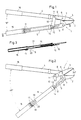
- the hand shears 1 shown in the drawing can be used in a particularly advantageous manner as branch, hedge and / or garden shears.
- the hand scissors 1 have the two shear blades 2 and 3 and the two hand levers 4 and 5.
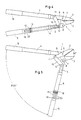
- the two shear knives 2 and 3 have a constant opening angle, for example of 34, between their closed position, which can be seen in FIGS. 1 and 4, and their opening position, which in turn can be seen in FIGS. 2 and 5 o , are adjustable, regardless of whether the two hand levers 4 and 5 used to actuate them are relatively relative to one another over a relatively small angular range - see FIGS. 1 and 2 - or over a relatively large angular range - see FIGS. 4 and 5 - can be adjusted.
- a constant opening angle for example of 34
- the two shear knives 2 and 3 are pivotally connected to one another by a common joint.
- the shear knife 2 is rigidly connected to the hand lever 4, specifically via a side arm 7, which can be clearly seen in FIGS. 1 and 2 and 4 and 5 and which itself can be designed as a lower shear knife 2.
- This boom 7 carries a further joint 8 offset parallel to the shear knife joint 6, via which the two hand levers 4 and 5 are in direct connection with one another independently of the shear knives 2 and 3.
- the scissors can also have two other cutting elements, for example an anvil and a cutting edge working against it.
- the anvil forming the lower cutting element can be screwed to the side of the boom 7.
- the operative connection of the shear knife 3 with the second hand lever 5 is established in that the shear knife 3 has a drive arm 9 which projects over the shear knife joint 6 and on which a coupling 10 engages at one end in an articulated manner via a pivot axis 11. On the other hand, this coupling is also articulated to the second hand lever 5 via a further articulation axis 12. All of the joints 6 and 8 and articulation axes 11 and 12 extend in the same direction, that is to say parallel to one another and normal to the pivoting plane of the shear blades 2 and 3 and the hand levers 4 and 5.
- Transmission links form a four-bar system with the transmission links a, b, c and d.
- the gear member a is the drive arm 9 for the shear knife 3
- the gear member b is formed by the coupling 10
- the gear member c is the arm 7 of the hand lever 4.
- the length section of the hand lever 5 located between the joint 8 and the articulation axis 12 acts as the transmission member d.
- the transmission members a, b and c of the four-bar system have a constant, that is to say unchangeable, effective length.
- the effective length of the transmission link d in the four-bar system can be varied within predetermined limits. The greatest effective length has the gear member d, in the setting shown in FIGS. 1 and 2.
- the setting in which the gear member d has its smallest effective length can be seen from FIGS. 4 and 5 of the drawing.
- the force transmission ratio of the hand levers 4 and 5 to the shear blades 2 and 3 can be varied with the aid of the four-bar system.
- the hand scissors 1 are set for their smallest possible power transmission ratio.
- the hand scissors with the smallest possible setting of the gear member d according to FIGS. 4 and 5 have their greatest possible power transmission ratio.
- the different power transmission ratios are characterized in that the hand levers 4 and 5 can be moved relative to one another only by a relatively small pivoting angle, see FIGS. 1 and 2 shift relative to each other over a large swivel angle - see FIGS. 4 and 5.
- the gear member b has the greatest effective length in the four-bar system, while the gear member d works there with the smallest effective length in the four-bar system.
- the articulation axis 12 for the coupling 10 on the hand lever 5 engages in the slot guide 13 in the latter. This runs on a circular arc around the articulation axis 11 with a radius of the length of the gear member b (coupling 10). This makes it possible to change the translation with the scissors closed without changing the position of the hand levers 4, 5.
- a slide 14 is in constant connection with the articulation axis 12 and protrudes over most of its length into the hand lever 5, which is at least partially designed as a tube or hollow profile, as can be clearly seen in FIG. 3 of the drawing.
- the slide 14 is guided into the area of an operating handle 15, which is formed by the rear end of the hand lever 5 or is attached to it.
- a corresponding operating handle 16 is of course also located at the free end of the hand lever 4 of the hand scissors 1.
- An adjustment and locking device 17 is coupled to the slide 14, which in turn interacts with the hand lever 5.
- the rotatable threaded member can also be at a distance from the operating handle 15 and be included in sections of the hand lever 5 so that it protrudes segment-like from the broad sides of the hand lever profile for actuation.
- the setting and locking device is formed by a latching member 18 engaging the slide 14, which cooperates with a latching link 19 extending in the longitudinal direction of the hand lever 5.
- this latching link 19 is equipped with a plurality of latching engagements 20 which are arranged one behind the other and into which the latching member 18 can engage in a non-positive and positive manner.
- the locking member 18 is preferably located on a push button which is mounted on a spring element 21 carried by the slide 14.
- the spring element 21 is designed so that it tries to keep the locking member 18 with the locking handles 20 of the locking link 19 in engagement.
- the latching element 18 can be engaged with the latches against the restoring force of the spring element 21 Gripped 20 of the locking link 19 disengage and at the same time move the slide in order to change the length of the link d in one direction or the other.
- the locking element 18 then moves under the restoring force of the spring element 21 into the locking engagement 20 of the locking link 19 closest to it, so that the corresponding setting of the four-bar system is fixed.
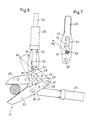
- the hand scissors 21 shown in FIG. 6 of the drawing have the same design as the hand scissors 1 according to FIGS. 1 to 5. It therefore has the two shear blades 22 and 23 and the two hand levers 24 and 25.
- the two shear blades 22 and 23 have a common joint 26 and the two hand levers 24 and 25 are in constant communication with one another by means of a further joint 28.
- the shear knife 23 has a drive arm 29 projecting over the joint 26, with which a coupling 30 is in constant communication via a link axis 31, which on the other hand has a link axis 32 with which it is guided in a slot guide 33 on the hand lever 25.
- the shear knife 22 is rigidly connected to the hand lever 24 via a laterally directed arm 27, the arm 27 also carrying the joint 28 for the hand lever 25.
- the articulation axis 32 of the coupling 30 can be displaced within the slot guide 33 by means of a slide 34 within the limits determined by the length of the slot guide 33.
- the two locking troughs 41 and 43 are provided on the ends of the slot guide directed away from one another, while the third locking trough 42 is located approximately halfway along the length of the slot guide 33.
- the coupling 30 forming the transmission link b in the four-bar system a, b, c, d generates a coupling force Fk in the direction of its longitudinal axis, as can be seen from the parallelogram of forces indicated in FIG. 6.
- This coupling force Fk is divided into the tangential component Ft and the radial component Fr.
- the tangential component Ft acts as a compressive force on the slide 34, which normally has to be absorbed by the adjusting and locking device interacting with the slide 34 (see locking device 17 in FIGS. 1 to 5).
- the receiving or locking troughs 41, 42, 43 are now provided in the slot guide 33 so that the coupling force Fk is safely absorbed by them because the articulation axis 32 of the coupling 30 receives a secure support system therein .
- the coupling force Fk is thus fully absorbed in the transmission link d of the four-bar system, i.e. the setting and locking device is relieved of this.
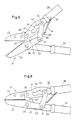
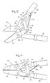
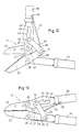
- the hand scissors 21 shown in FIGS. 8 to 13 basically have the same design as the hand scissors 21 according to FIGS. 6 and 7. The only difference is that there the slide 34 and an adjusting and locking device cooperating with it is not present on the hand lever 25.
- a spring element 44 in particular a tension spring 44, is installed between the coupling 30 and the hand lever 25.
- This tension spring 44 is anchored on the one hand at 45 on the hand lever 25 and engages at 46 in the distance between the two articulation axes 31 and 32 on the coupling 30.
- the point of engagement 46 of the tension spring 44 on the coupling 30 lies outside a straight connecting line through the two articulation axes 31 and 32 and is furthermore closer to the articulation axis 31 than to the articulation axis 32.
- a stop 47 is seated on the boom 27 between the shear knife 22 and the hand lever 24, with which the drive arm 29 of the shear knife 23 can be operatively connected in order to limit the maximum opening angle between the two shear knives 22 and 23.
- the hand scissors 21 according to FIGS. 8 to 13 offer the possibility of a somewhat automatic adjustment of the transmission ratio between the two hand levers 24 and 25 and the two shear blades 22 and 23.
- the coupling 30 is in the closed state shown in FIG. 8 under the action of the tension spring 44 in a position in which its articulation axis 32 lies in the receiving or locking recess 43. If the shear blades 22 and 23 are brought into the largest possible open position relative to one another, as shown in FIG. 9, then the drive arm 29 of the shear blade 23 runs against the stop 47. However, the hand lever 25 can be moved beyond the position according to FIG. 9, for example up to the position according to FIG. 10. As a result, the articulation axis 32 of the coupling 30 then disengages from the receiving or locking trough 43 and slides into the area of the receiving or locking trough 42 of the slot guide 33, as can be seen in FIGS. 10 and 11.
- the two hand levers 24 and 25 In order to set the largest possible transmission ratio for the hand scissors 21, the two hand levers 24 and 25 must be moved apart to the angular position corresponding to FIG. 12. As a result, the coupling 30 then falls with its articulation axis 32 into the receiving or locking trough 41 and is automatically fixed in this, despite the greatest possible pretensioning of the tension spring 44. This is due to the fact that the fastening points 45 and 46 of the tension spring 44 with the articulation axis 31 lie between the coupling 30 and the drive arm 29 of the shear knife 23 in a straight line.
Landscapes
- Life Sciences & Earth Sciences (AREA)
- Biodiversity & Conservation Biology (AREA)
- Ecology (AREA)
- Forests & Forestry (AREA)
- Environmental Sciences (AREA)
- Scissors And Nippers (AREA)
- Harvester Elements (AREA)
- Shovels (AREA)
Applications Claiming Priority (4)
| Application Number | Priority Date | Filing Date | Title |
|---|---|---|---|
| DE3929891 | 1989-09-08 | ||
| DE3929891 | 1989-09-08 | ||
| DE4015021A DE4015021A1 (de) | 1989-09-08 | 1990-05-10 | Hand-schere, insbesondere ast-, hecken- und/oder gartenschere |
| DE4015021 | 1990-05-10 |
Publications (2)
| Publication Number | Publication Date |
|---|---|
| EP0421108A1 true EP0421108A1 (fr) | 1991-04-10 |
| EP0421108B1 EP0421108B1 (fr) | 1994-10-05 |
Family
ID=25884907
Family Applications (1)
| Application Number | Title | Priority Date | Filing Date |
|---|---|---|---|
| EP90116145A Expired - Lifetime EP0421108B1 (fr) | 1989-09-08 | 1990-08-23 | Cisailles à main, en particulier sécateur, cisailles à haies et/ou de jardinage |
Country Status (6)
| Country | Link |
|---|---|
| US (1) | US5159757A (fr) |
| EP (1) | EP0421108B1 (fr) |
| JP (1) | JPH0767509B2 (fr) |
| AT (1) | ATE112446T1 (fr) |
| DE (2) | DE4015021A1 (fr) |
| ES (1) | ES2064566T3 (fr) |
Cited By (5)
| Publication number | Priority date | Publication date | Assignee | Title |
|---|---|---|---|---|
| EP0525569A2 (fr) | 1991-07-23 | 1993-02-03 | WOLF-Geräte GmbH Vertriebsgesellschaft KG | Sécateur pour arbres |
| GB2302665B (en) * | 1995-06-28 | 1998-08-19 | Huang Shoei Shin | Garden shears |
| DE202008014291U1 (de) | 2008-10-17 | 2009-01-22 | Hidde, Axel R., Dr. | Schneidende Handwerkzeuge |
| CN106576948A (zh) * | 2016-11-25 | 2017-04-26 | 安徽省农业科学院园艺研究所 | 一种园林专用多功能调头剪刀的加压装置 |
| DE102017009982A1 (de) | 2017-10-26 | 2019-05-02 | Mtd Products Inc. | Handschere, insbesondere Ast-, Hecken- und/oder Gartenschere |
Families Citing this family (47)
| Publication number | Priority date | Publication date | Assignee | Title |
|---|---|---|---|---|
| USD356719S (en) | 1993-03-11 | 1995-03-28 | Bando Industrial Co., Ltd. | Lopping shears |
| US5511314A (en) * | 1995-06-16 | 1996-04-30 | Huang; Shoei-Shin | Garden shears |
| US5566453A (en) * | 1995-09-18 | 1996-10-22 | Lin; Ching-Shui | Nippers for gardening |
| DE69734412T2 (de) * | 1996-08-28 | 2006-06-01 | Thomas & Betts Corp., Memphis | Kabelbinder-Installationswerkzeug |
| US5709030A (en) * | 1996-11-05 | 1998-01-20 | Wang; Meng Tun | Garden shear control mechanism |
| DE19712170A1 (de) * | 1997-03-22 | 1997-11-20 | Karl Hymer | Gartenschere mit Hebelkraftunterstützung und Mehrfachhub |
| US5839195A (en) * | 1997-04-22 | 1998-11-24 | Lin; Yu-Tang | Gardening shears |
| US6513248B2 (en) | 2000-12-20 | 2003-02-04 | Fiskars Consumer Oy Ab | Power lever cutting device |
| US6752054B2 (en) * | 2000-12-28 | 2004-06-22 | Irwin Industrial Tool Company | Utility cutting tool having toggle link mechanism field of the invention |
| US6481106B1 (en) | 2001-01-03 | 2002-11-19 | Fiskars Consumer Oy Ab | Scissor action tool |
| US7596870B2 (en) | 2004-03-02 | 2009-10-06 | Leatherman Tool Group, Inc. | Folding multipurpose tool with shears and comfortable handles |
| DE102004032464A1 (de) * | 2004-07-05 | 2006-02-16 | Wolf-Geräte AG | Insbesondere als Heckenschere ausgebildete Handschere |
| US7204021B2 (en) * | 2005-05-16 | 2007-04-17 | Eric M. Houseman | Multi-purpose plastic pipe cutter |
| US7353736B2 (en) | 2005-07-27 | 2008-04-08 | Leatherman Tool Group, Inc. | Enhanced multi-function hand tool |
| US20080016700A1 (en) * | 2006-07-18 | 2008-01-24 | Hernandez Hector R | High leverage bolt cutter |
| US7574805B1 (en) | 2006-12-13 | 2009-08-18 | Ulf Lindroth | Rotating branch trimmer |
| USD576010S1 (en) | 2007-03-09 | 2008-09-02 | Leatherman Tool Group, Inc. | Rotatable tool handle |
| USD567601S1 (en) | 2007-03-09 | 2008-04-29 | Leatherman Tool Group, Inc. | Multipurpose tool including bypass pruner |
| WO2008120213A2 (fr) * | 2007-04-02 | 2008-10-09 | Mordechai Uzrad | Outil de coupe à double action |
| US7966735B1 (en) * | 2008-04-04 | 2011-06-28 | Hasbro, Inc. | Scissors assembly with rotatable blades |
| US20100107426A1 (en) * | 2008-11-04 | 2010-05-06 | Staples The Office Superstore, Llc | Hand-held hole punch |
| US8046924B2 (en) * | 2009-03-03 | 2011-11-01 | Fiskars Brands, Inc. | Cutting tool with variable mechanical advantage |
| JP5222263B2 (ja) * | 2009-10-05 | 2013-06-26 | ミノル工業株式会社 | ケーブルカッター |
| CN201630052U (zh) * | 2009-11-04 | 2010-11-17 | 王光彬 | 一种新型园艺剪 |
| US8166659B2 (en) * | 2009-11-29 | 2012-05-01 | Ho Cheng Garden Tools Co., Ltd. | Garden shears |
| CN201630054U (zh) * | 2009-12-25 | 2010-11-17 | 杭州埃法花园设备有限公司 | 双重加力树枝剪 |
| US20110192035A1 (en) * | 2010-02-09 | 2011-08-11 | Wen Ger Chen | Compound-action pruning tools |
| US8225513B2 (en) * | 2010-03-02 | 2012-07-24 | Ho Cheng Garden Tools Co., Ltd. | Gardening shears having energy-saving function |
| US20110258860A1 (en) * | 2010-04-27 | 2011-10-27 | Irwin Industrial Tool Company | Optimized mechanical advantage cutting tool |
| US9339938B2 (en) | 2010-10-08 | 2016-05-17 | Milwaukee Electric Tool Corporation | Powered cutting tool |
| US8661691B2 (en) * | 2011-01-20 | 2014-03-04 | Ho Cheng Garden Tools Co., Ltd. | Garden shears |
| USD668922S1 (en) | 2012-01-20 | 2012-10-16 | Milwaukee Electric Tool Corporation | Powered cutting tool |
| US8881407B2 (en) * | 2013-02-07 | 2014-11-11 | Green Guard Industry Ltd. | Multifunctional pruning shears for one step cutting and step by step cutting |
| US20160120132A1 (en) * | 2014-11-04 | 2016-05-05 | Formosa Tools Co., Ltd. | Pruning shears |
| FR3033979B1 (fr) * | 2015-03-23 | 2017-10-13 | Deville Sa | Outil de coupe a deux mains comprenant une poignee tournante |
| US9918435B2 (en) * | 2015-09-24 | 2018-03-20 | Kuang Pin Wang | Tree shear capable of reducing opening degree of handles thereof |
| DE102015117525B3 (de) * | 2015-10-15 | 2017-03-09 | Kuang Pin Wang | Öffnungswinkel-verkleinernde Baumschere |
| CN107771548A (zh) * | 2017-11-20 | 2018-03-09 | 梧州市雅正农业科技有限公司 | 一种茶树可伸缩园林剪 |
| DE102018251740A1 (de) * | 2018-12-27 | 2020-07-02 | Robert Bosch Gmbh | Schneidvorrichtung |
| US12310300B2 (en) * | 2021-03-31 | 2025-05-27 | Techtronic Cordless Gp | Hand tool with shear assembly |
| US12471539B2 (en) * | 2021-04-29 | 2025-11-18 | Techtronic Cordless Gp | Hand tool with shear assembly |
| WO2022235471A1 (fr) * | 2021-05-03 | 2022-11-10 | Task Force Tips, Llc | Pince pour un tuyau flexible ou un tube |
| CN115921720A (zh) * | 2022-12-16 | 2023-04-07 | 威海市威力高档工具有限公司 | 一种剪切钢丝绳的省力工具 |
| EP4406404A1 (fr) * | 2023-01-24 | 2024-07-31 | Fiskars Finland Oy Ab | Outil de coupe |
| US12642190B2 (en) * | 2023-07-17 | 2026-06-02 | Paul Janson | Variable force compound cutting lopper |
| DE102023119825B3 (de) | 2023-07-26 | 2024-09-26 | Vladlen Bedrin | Schere |
| CN118849055B (zh) * | 2024-08-08 | 2026-07-28 | 深圳绿威科技有限公司 | 一种电剪刀解锁控制方法、系统及电剪刀 |
Citations (3)
| Publication number | Priority date | Publication date | Assignee | Title |
|---|---|---|---|---|
| US1607470A (en) * | 1922-01-07 | 1926-11-16 | Mckenney Emerson | Pruner |
| DE1553692A1 (de) * | 1966-01-14 | 1971-05-19 | Florian Steuart Rodriguez | Baumschere |
| FR2348022A1 (fr) * | 1976-04-16 | 1977-11-10 | Matsuzaka Iron Works Inc | Cisaille pour tubes en resine synthetique |
Family Cites Families (16)
| Publication number | Priority date | Publication date | Assignee | Title |
|---|---|---|---|---|
| GB601072A (en) * | 1945-09-11 | 1948-04-27 | Robert Griffiths | Improvement in shears or secateurs |
| US993646A (en) * | 1909-12-07 | 1911-05-30 | J I Zigler | Shears. |
| US1577140A (en) * | 1924-10-08 | 1926-03-16 | Mitchell Isaac Newton | Dehorning implement |
| US2384822A (en) * | 1944-04-04 | 1945-09-18 | Stipan A Drmic | Gripping or cutting tool |
| US2520905A (en) * | 1946-10-01 | 1950-09-05 | Elmer F Borrelli | Shears |
| US3243880A (en) * | 1963-09-03 | 1966-04-05 | Robert W Weller | Power pincers |
| US3273240A (en) * | 1964-05-11 | 1966-09-20 | Steuart R Florian | Cutting tool |
| US3587173A (en) * | 1968-10-21 | 1971-06-28 | Andrew M Hexdall | Metal-cutting shears |
| US3839794A (en) * | 1973-05-25 | 1974-10-08 | J Deale | Shears |
| US3851389A (en) * | 1973-08-29 | 1974-12-03 | L Swanson | Multiple adjustment shear |
| DE2508973A1 (de) * | 1975-03-01 | 1976-09-09 | Erwin Gude | Verstellbare baumschere mit drehbarer schneidbacke |
| US4094064A (en) * | 1976-04-16 | 1978-06-13 | Matsuzaka Iron Works, Inc. | Shearing tool for synthetic resin tubes |
| JPS5532061Y2 (fr) * | 1977-01-25 | 1980-07-31 | ||
| US4312127A (en) * | 1979-08-23 | 1982-01-26 | Hanazono Kogu Kabushiki Kaisha | Cutting tool |
| JPS56101965U (fr) * | 1979-12-29 | 1981-08-11 | ||
| DE3808568A1 (de) * | 1988-03-15 | 1989-09-28 | Dambroth Juergen P | Druckhebel astschere |
-
1990
- 1990-05-10 DE DE4015021A patent/DE4015021A1/de not_active Withdrawn
- 1990-08-23 EP EP90116145A patent/EP0421108B1/fr not_active Expired - Lifetime
- 1990-08-23 AT AT90116145T patent/ATE112446T1/de not_active IP Right Cessation
- 1990-08-23 DE DE59007381T patent/DE59007381D1/de not_active Expired - Lifetime
- 1990-08-23 ES ES90116145T patent/ES2064566T3/es not_active Expired - Lifetime
- 1990-09-07 JP JP2238843A patent/JPH0767509B2/ja not_active Expired - Lifetime
-
1992
- 1992-01-21 US US07/824,695 patent/US5159757A/en not_active Expired - Lifetime
Patent Citations (3)
| Publication number | Priority date | Publication date | Assignee | Title |
|---|---|---|---|---|
| US1607470A (en) * | 1922-01-07 | 1926-11-16 | Mckenney Emerson | Pruner |
| DE1553692A1 (de) * | 1966-01-14 | 1971-05-19 | Florian Steuart Rodriguez | Baumschere |
| FR2348022A1 (fr) * | 1976-04-16 | 1977-11-10 | Matsuzaka Iron Works Inc | Cisaille pour tubes en resine synthetique |
Cited By (9)
| Publication number | Priority date | Publication date | Assignee | Title |
|---|---|---|---|---|
| EP0525569A2 (fr) | 1991-07-23 | 1993-02-03 | WOLF-Geräte GmbH Vertriebsgesellschaft KG | Sécateur pour arbres |
| EP0525569A3 (en) * | 1991-07-23 | 1993-04-14 | Wolf-Geraete Gmbh Vertriebsgesellschaft Kg | Secateurs for trees |
| US5325591A (en) * | 1991-07-23 | 1994-07-05 | Wolf-Gerate Gmbh | Branch pruning shears |
| GB2302665B (en) * | 1995-06-28 | 1998-08-19 | Huang Shoei Shin | Garden shears |
| DE202008014291U1 (de) | 2008-10-17 | 2009-01-22 | Hidde, Axel R., Dr. | Schneidende Handwerkzeuge |
| DE102008051810A1 (de) | 2008-10-17 | 2010-04-22 | Hidde, Axel R., Dr. | Schneidende Handwerkzeuge |
| CN106576948A (zh) * | 2016-11-25 | 2017-04-26 | 安徽省农业科学院园艺研究所 | 一种园林专用多功能调头剪刀的加压装置 |
| CN106576948B (zh) * | 2016-11-25 | 2021-06-08 | 安徽省农业科学院园艺研究所 | 一种园林专用多功能调头剪刀的加压装置 |
| DE102017009982A1 (de) | 2017-10-26 | 2019-05-02 | Mtd Products Inc. | Handschere, insbesondere Ast-, Hecken- und/oder Gartenschere |
Also Published As
| Publication number | Publication date |
|---|---|
| JPH03139386A (ja) | 1991-06-13 |
| JPH0767509B2 (ja) | 1995-07-26 |
| EP0421108B1 (fr) | 1994-10-05 |
| DE59007381D1 (de) | 1994-11-10 |
| US5159757A (en) | 1992-11-03 |
| ATE112446T1 (de) | 1994-10-15 |
| ES2064566T3 (es) | 1995-02-01 |
| DE4015021A1 (de) | 1991-04-04 |
Similar Documents
| Publication | Publication Date | Title |
|---|---|---|
| EP0421108B1 (fr) | Cisailles à main, en particulier sécateur, cisailles à haies et/ou de jardinage | |
| DE69800491T2 (de) | Baumschere | |
| DE60107760T2 (de) | Schneidegerät, insbesondere Heckenschere | |
| DE69707784T2 (de) | Werkzeug mit variabler Kraft | |
| DE60128533T2 (de) | Hebelschere | |
| EP0176784B1 (fr) | Sécateur pour arbres | |
| EP1996091A2 (fr) | Instrument chirurgical | |
| EP1625784B1 (fr) | Outil de coupe manuel, en particulier un taille-haie ou sécateur | |
| DE3714302A1 (de) | Schere | |
| DE29708232U1 (de) | Gartenschere | |
| EP0299387A1 (fr) | Outil pour tendre et sectionner une bande de cerclage | |
| DE20120275U1 (de) | Kabelschneider | |
| DE4023559C2 (de) | Schere | |
| DE3345870A1 (de) | Ausstellvorrichtung fuer fenster, tueren oder dergleichen mit dreh-kippfluegel | |
| DE1932858C3 (de) | Durch ein Gestänge schwenkbare Ausstellschere für Fensterflügel oder dergleichen, insbesondere Oberlichter | |
| DE19537994C2 (de) | Handhebelschere zum Abtrennen von Profilwerkstoff | |
| DE2810903C3 (de) | Überlastsicherung für einen Pflug | |
| EP3476205B1 (fr) | Cisailles à main, en particulier un sécateur, cisailles à haies et/ou de jardinage | |
| EP0155692A2 (fr) | Machine agricole | |
| DE69607645T2 (de) | Mehrzweckzange | |
| EP3456211A2 (fr) | Dispositif de montage d'au moins un doigt | |
| EP1827770B1 (fr) | Cisaille, en particulier taille-haie | |
| DE19523566C1 (de) | Handbetätigter Ratschenschneider, insbesondere Kabelschneider | |
| DE4229221A1 (de) | Zange mit verstellbarer Maulweite | |
| DE1954491C3 (de) | Selbsteinstellender Spannschlüssel |
Legal Events
| Date | Code | Title | Description |
|---|---|---|---|
| PUAI | Public reference made under article 153(3) epc to a published international application that has entered the european phase |
Free format text: ORIGINAL CODE: 0009012 |
|
| 17P | Request for examination filed |
Effective date: 19900829 |
|
| AK | Designated contracting states |
Kind code of ref document: A1 Designated state(s): AT BE CH DE DK ES FR GB IT LI NL SE |
|
| 17Q | First examination report despatched |
Effective date: 19920507 |
|
| GRAA | (expected) grant |
Free format text: ORIGINAL CODE: 0009210 |
|
| AK | Designated contracting states |
Kind code of ref document: B1 Designated state(s): AT BE CH DE DK ES FR GB IT LI NL SE |
|
| PG25 | Lapsed in a contracting state [announced via postgrant information from national office to epo] |
Ref country code: DK Effective date: 19941005 |
|
| REF | Corresponds to: |
Ref document number: 112446 Country of ref document: AT Date of ref document: 19941015 Kind code of ref document: T |
|
| REF | Corresponds to: |
Ref document number: 59007381 Country of ref document: DE Date of ref document: 19941110 |
|
| ITF | It: translation for a ep patent filed | ||
| EAL | Se: european patent in force in sweden |
Ref document number: 90116145.5 |
|
| REG | Reference to a national code |
Ref country code: ES Ref legal event code: FG2A Ref document number: 2064566 Country of ref document: ES Kind code of ref document: T3 |
|
| ET | Fr: translation filed | ||
| GBT | Gb: translation of ep patent filed (gb section 77(6)(a)/1977) |
Effective date: 19950113 |
|
| PLBE | No opposition filed within time limit |
Free format text: ORIGINAL CODE: 0009261 |
|
| STAA | Information on the status of an ep patent application or granted ep patent |
Free format text: STATUS: NO OPPOSITION FILED WITHIN TIME LIMIT |
|
| 26N | No opposition filed | ||
| REG | Reference to a national code |
Ref country code: CH Ref legal event code: NV Representative=s name: ULRICH UND BRIGITTE BALLMER PATENTANWAELTE |
|
| PGFP | Annual fee paid to national office [announced via postgrant information from national office to epo] |
Ref country code: CH Payment date: 19990708 Year of fee payment: 10 |
|
| PG25 | Lapsed in a contracting state [announced via postgrant information from national office to epo] |
Ref country code: CH Free format text: LAPSE BECAUSE OF NON-PAYMENT OF DUE FEES Effective date: 20000831 Ref country code: LI Free format text: LAPSE BECAUSE OF NON-PAYMENT OF DUE FEES Effective date: 20000831 |
|
| REG | Reference to a national code |
Ref country code: CH Ref legal event code: PL |
|
| REG | Reference to a national code |
Ref country code: GB Ref legal event code: IF02 |
|
| PGFP | Annual fee paid to national office [announced via postgrant information from national office to epo] |
Ref country code: FR Payment date: 20090717 Year of fee payment: 20 Ref country code: ES Payment date: 20090827 Year of fee payment: 20 |
|
| PGFP | Annual fee paid to national office [announced via postgrant information from national office to epo] |
Ref country code: GB Payment date: 20090827 Year of fee payment: 20 Ref country code: NL Payment date: 20090728 Year of fee payment: 20 Ref country code: SE Payment date: 20090813 Year of fee payment: 20 Ref country code: DE Payment date: 20090724 Year of fee payment: 20 Ref country code: AT Payment date: 20090720 Year of fee payment: 20 |
|
| PGFP | Annual fee paid to national office [announced via postgrant information from national office to epo] |
Ref country code: BE Payment date: 20090915 Year of fee payment: 20 |
|
| PGFP | Annual fee paid to national office [announced via postgrant information from national office to epo] |
Ref country code: IT Payment date: 20090822 Year of fee payment: 20 |
|
| BE20 | Be: patent expired |
Owner name: *WOLF-GERATE G.M.B.H. VERTRIEBSGESELLSCHAFT K.G. Effective date: 20100823 |
|
| REG | Reference to a national code |
Ref country code: NL Ref legal event code: V4 Effective date: 20100823 |
|
| REG | Reference to a national code |
Ref country code: GB Ref legal event code: PE20 Expiry date: 20100822 |
|
| EUG | Se: european patent has lapsed | ||
| REG | Reference to a national code |
Ref country code: ES Ref legal event code: FD2A Effective date: 20100824 |
|
| PG25 | Lapsed in a contracting state [announced via postgrant information from national office to epo] |
Ref country code: NL Free format text: LAPSE BECAUSE OF EXPIRATION OF PROTECTION Effective date: 20100823 |
|
| PG25 | Lapsed in a contracting state [announced via postgrant information from national office to epo] |
Ref country code: GB Free format text: LAPSE BECAUSE OF EXPIRATION OF PROTECTION Effective date: 20100822 |
|
| PG25 | Lapsed in a contracting state [announced via postgrant information from national office to epo] |
Ref country code: DE Free format text: LAPSE BECAUSE OF EXPIRATION OF PROTECTION Effective date: 20100823 |