EP0421119A1 - Indicateur passif de mouvement infrarouge - Google Patents
Indicateur passif de mouvement infrarouge Download PDFInfo
- Publication number
- EP0421119A1 EP0421119A1 EP90116453A EP90116453A EP0421119A1 EP 0421119 A1 EP0421119 A1 EP 0421119A1 EP 90116453 A EP90116453 A EP 90116453A EP 90116453 A EP90116453 A EP 90116453A EP 0421119 A1 EP0421119 A1 EP 0421119A1
- Authority
- EP
- European Patent Office
- Prior art keywords
- infrared
- incident
- fresnel lens
- detection
- motion detector
- Prior art date
- Legal status (The legal status is an assumption and is not a legal conclusion. Google has not performed a legal analysis and makes no representation as to the accuracy of the status listed.)
- Granted
Links
Images


Classifications
-
- G—PHYSICS
- G08—SIGNALLING
- G08B—SIGNALLING SYSTEMS, e.g. PERSONAL CALLING SYSTEMS; ORDER TELEGRAPHS; ALARM SYSTEMS
- G08B13/00—Burglar, theft or intruder alarms
- G08B13/18—Actuation by interference with heat, light, or radiation of shorter wavelength; Actuation by intruding sources of heat, light, or radiation of shorter wavelength
- G08B13/189—Actuation by interference with heat, light, or radiation of shorter wavelength; Actuation by intruding sources of heat, light, or radiation of shorter wavelength using passive radiation detection systems
- G08B13/19—Actuation by interference with heat, light, or radiation of shorter wavelength; Actuation by intruding sources of heat, light, or radiation of shorter wavelength using passive radiation detection systems using infrared-radiation detection systems
- G08B13/193—Actuation by interference with heat, light, or radiation of shorter wavelength; Actuation by intruding sources of heat, light, or radiation of shorter wavelength using passive radiation detection systems using infrared-radiation detection systems using focusing means
Definitions
- the invention relates to a passive infrared motion detector according to the preamble of claim 1.
- Passive infrared motion detectors are essentially devices which trigger a switching process as a function of the detected infrared radiation of an object emitting heat radiation. They are used to monitor a room area for moving objects, whereby the passive infrared motion detectors e.g. react to the change in thermal radiation in the area to be monitored. Such an infrared radiation object is e.g. a person who moves in a room to be monitored.
- a passive infrared motion detector only works as a receiver of infrared heat radiation, whereas other types of infrared motion detectors have an active infrared transmitter.
- a passive infrared motion detector with an azimuthal detection angle of 180 ° which has an infrared sensitive sensor inside a housing.
- a wide-angle collecting optic in particular especially a Fresnel plastic lens.
- frontally incident infrared rays from the detection area to be monitored are bundled directly onto the infrared sensor, whereas laterally infrared rays incident from the detection area are focused on the infrared sensor only after intermediate reflection on a deflecting mirror system.
- the largest possible detection range with passive sensitivity is aimed at passive infrared motion detectors. Due to the fact that in the passive infrared motion detector known from the prior art, the infrared rays that are incident laterally from the detection range are focused on the infrared sensor by means of intermediate reflection on a deflecting mirror system, the intensity of the incident on the infrared sensor is ultimately due to scattering losses Radiation is reduced compared to the radiation emitted directly by the object. This leads to a narrowing of the detection characteristic in the lateral area.
- the passive infrared motion detector known in the prior art is highly sensitive, in particular to temperature changes occurring in the front detection area.
- this fundamentally desirable fact is disadvantageous if switching operations are already triggered by objects which are not intentionally detected, in particular small animals, or by air currents passing by.
- the measure known in the prior art has proven itself to be arranged on the sensor side, at a distance behind the plastic Fresnel lens, to arrange a plastic film which transmits infrared radiation. This has two effects.
- the entire frontal and lateral infrared radiation is attenuated in intensity, and secondly, a heat-insulating air cushion is generated between the plastic Fresnel lens and the plastic damping film, which creates the heat generated inside the passive infrared motion detector due to the evaluation electronics there does not let outside.
- additional attenuation means are provided in the beam path of the infrared rays incident on the infrared sensor from the front detection area compared to the infrared rays incident on the lateral detection area.
- This has the effect that the transmittance for the infrared rays incident from the front detection area is lower than the transmittance of the infrared rays incident on the infrared sensor from the lateral detection area.
- the transmittance is defined as the ratio of the radiation intensity weakened after passing through a medium to the initial radiation intensity, the initial radiation intensity in the beam path in front of the Fresnel lens and the weakened radiation intensity being measured directly in front of the infrared sensor.
- An infrared-permeable plastic film is advantageously provided as a damping means in the beam path of the frontally incident infrared rays, the transmittance of which is known to be essentially a function of the infrared wavelength to be transmitted, the material and the film thickness.
- films have proven their worth, the transmittance of which is between 58% and 68% at a wavelength of 10 ⁇ m.
- the damping effect can also be achieved with other measures, e.g. by means of a varnish applied to the Fresnel plastic lens or by a different thickness of the Fresnel plastic lens.
- the use of a plastic damping film offers the advantage that a heat insulation layer is present in the front detection area, in which the detection sensitivity is particularly high, because of the aforementioned air cushion, due to which undesired switching operations can be largely prevented.
- the Fresnel lens system used as a wide-angle collecting optic is realized by a plastic Fresnel lens which is bent in a semicircular convex manner into the detection area.
- stripe-shaped segments covering the azimuthal detection area are semicircular mig arranged side by side, which have Fresnel lenses stamped into the plastic film.
- At least two zones of segmented central Fresnel lenses are provided for the detection of the infrared rays incident from the front detection area. This makes it impossible to undermine the frontal detection area.
- segments with acentric Fresnel lenses are arranged laterally next to the segments assigned to the frontally incident infrared rays.
- the teaching according to the invention combined with the acentric Fresnel lenses described above thus offers the decisive advantage that the azimuthal detection range of the passive infrared motion detector extends beyond 180 ° to e.g. Can be extended by 220 °.
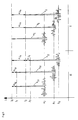
- FIG. 1 shows a frontal view of the passive infrared motion detector 1 according to the invention with a window-like housing recess 3 in a housing 2.
- a Fresnel lens film 4 made of plastic is clamped in a semicircular convex manner in the housing recess 3.
- Infrared rays S I incident frontally from a first detection area I are bundled directly onto infrared sensors 9 by means of the Fresnel lens film 4.
- Infrared rays S II incident laterally from a second detection area II are focused on the infrared sensors 9 with the Fresnel lens film 4 only after intermediate reflection at two deflecting mirrors 8.
- the Fresnel lens plastic film 4 is convex in a semicircular shape into the detection areas I, II to be monitored and is held in a Fresnel lens mount 5 of the housing 2.
- I infrared rays S I-plastic film
- Fresnel lens 4 is permeable to infrared damping plastic film 6 provided in the beam path behind the and supported film version cushion 7 in a.
- An air cushion 10 is formed behind the Fresnel lens plastic film 4 and the damping plastic film 6, which is largely sealed off from the ambient air with the aid of end webs 11.
- the infrared sensors 9 are arranged centrally on a circuit board 12, onto which the infrared rays S II incident laterally from the second detection area II are focused via two deflecting mirrors 8. Frontal incident from the first detection area I I S infrared rays are bundled without intermediate reflection directly to the infrared sensors. 9
- FIG. 3 shows a first detection characteristic 13, known in the prior art, of the passive infrared motion detector 1 without a damping plastic film 6.
- a second detection characteristic 14 arises when both the frontally from the first detection area I and the laterally from the second detection area II the infrared rays S I , S II are additionally attenuated with the damping plastic film 6. It can be seen that the shape of the detection characteristics 13, 14 is essentially retained, whereas a detection range r which is variable over an azimuth angle ⁇ is reduced in the detection characteristic 14 compared to the detection characteristic 13.
- a fourth detection characteristic 17 results when the teaching according to the invention is used in combination with a Fresnel lens film 4, described in more detail below, with laterally acentric Fresnel lens segments 18. As a result, the azimuthal detection area can then be expanded by a third detection area III to a total of 220 ° (cf. also FIG. 2).
- Fig. 5 shows a comparison of various laterally and frontally incident infrared useful signals at different noise levels and different arrangements of the damping foils 6.
- a resulting noise level R2 is relatively high.
- the damping by the Fresnel lens plastic film is not considered in this qualitative discussion.
- a comparison of the curves a I , II shows that the signal / noise ratio of the frontally incident useful signal a I is greater than that of the laterally incident useful signal a II .
- an increased signal / noise ratio means higher sensitivity.
- a passive infrared motion detector in which both the frontal and the laterally incident infrared rays S I , S II are covered by a damping film 6, has a significantly reduced background noise R0.
- laterally incident useful signals C II are not only attenuated by the already mentioned proportion ⁇ I d , which is due to the scatter at the deflecting mirrors 8, but additionally attenuated by ⁇ I a by the damping plastic film 6.
- a frontally incident useful signal represented by curve C I has an intensity that is only reduced by the damping measure ⁇ I a .
- the laterally incident infrared rays S II have a more favorable signal-to-noise ratio than the frontally incident infrared rays S I. This results in the improved third detection characteristic 16 described above.
- Fresnel lens plastic film 4 which is divided into individual strip-shaped Fresnel lens segments 18.
- Each segment 18 represents a Fresnel lens, which bundles infrared rays S I , S II , S III from different spatial sectors.
- the frontally incident infrared rays S I are assigned two zones of Fresnel lens segments 18 arranged one above the other. This has the advantage that it is no longer possible to undermine the frontal detection area I.
- the Fresnel lens plastic film 4 is that the, preferably four, laterally arranged Fresnel lens segments 18 are designed as eccentric Fresnel lenses, the respective lens centers 19 of which lie outside the Fresnel lens segment 18.
Landscapes
- Physics & Mathematics (AREA)
- General Physics & Mathematics (AREA)
- Photometry And Measurement Of Optical Pulse Characteristics (AREA)
- Geophysics And Detection Of Objects (AREA)
- Transforming Light Signals Into Electric Signals (AREA)
- Switches Operated By Changes In Physical Conditions (AREA)
Applications Claiming Priority (2)
| Application Number | Priority Date | Filing Date | Title |
|---|---|---|---|
| DE3932943 | 1989-10-03 | ||
| DE3932943A DE3932943A1 (de) | 1989-10-03 | 1989-10-03 | Passiv-infrarot-bewegungsmelder |
Publications (2)
| Publication Number | Publication Date |
|---|---|
| EP0421119A1 true EP0421119A1 (fr) | 1991-04-10 |
| EP0421119B1 EP0421119B1 (fr) | 1994-06-22 |
Family
ID=6390724
Family Applications (1)
| Application Number | Title | Priority Date | Filing Date |
|---|---|---|---|
| EP90116453A Expired - Lifetime EP0421119B1 (fr) | 1989-10-03 | 1990-08-28 | Indicateur passif de mouvement infrarouge |
Country Status (4)
| Country | Link |
|---|---|
| EP (1) | EP0421119B1 (fr) |
| AT (1) | ATE107785T1 (fr) |
| DE (2) | DE3932943A1 (fr) |
| DK (1) | DK0421119T3 (fr) |
Cited By (6)
| Publication number | Priority date | Publication date | Assignee | Title |
|---|---|---|---|---|
| GB2251938A (en) * | 1991-01-15 | 1992-07-22 | Smiths Industries Plc | Passive infrared intruder detector |
| EP0666551A1 (fr) * | 1994-02-08 | 1995-08-09 | Gebrüder Merten Gmbh & Co. Kg | Détecteur de mouvement à infrarouge |
| DE4428628A1 (de) * | 1994-08-12 | 1996-02-15 | Merten Gmbh & Co Kg Geb | Infrarot-Bewegungsmelder |
| EP0652422A3 (fr) * | 1993-11-06 | 1996-02-21 | Abb Patent Gmbh | Dispositif pour recevoir des rayons lumineux. |
| GB2411470A (en) * | 2004-02-27 | 2005-08-31 | Optex Co Ltd | Passive infrared sensor |
| US9797769B2 (en) | 2012-11-13 | 2017-10-24 | Pyronix Limited | Infrared detection device and masking section |
Families Citing this family (3)
| Publication number | Priority date | Publication date | Assignee | Title |
|---|---|---|---|---|
| DE4011453A1 (de) * | 1990-04-09 | 1991-10-10 | Abb Patent Gmbh | Passiv-infrarot-bewegungsmelder |
| DE4137560C1 (fr) * | 1991-11-15 | 1993-02-25 | Abb Patent Gmbh, 6800 Mannheim, De | |
| DE4333707C2 (de) * | 1993-10-02 | 1996-12-05 | Insta Elektro Gmbh & Co Kg | Passiv-Infrarot-Bewegungsmelder |
Citations (5)
| Publication number | Priority date | Publication date | Assignee | Title |
|---|---|---|---|---|
| US3476948A (en) * | 1968-02-19 | 1969-11-04 | Sylvania Electric Prod | Optical intrusion detection system using reflected dual beam peripheral scanning |
| US4703171A (en) * | 1985-11-05 | 1987-10-27 | Target Concepts Inc. | Lighting control system with infrared occupancy detector |
| DE3710614A1 (de) * | 1987-03-31 | 1988-10-20 | Siedle & Soehne S | Bewegungsmelder |
| EP0323601A2 (fr) * | 1987-12-24 | 1989-07-12 | Asea Brown Boveri Aktiengesellschaft | Détecteur à radiations |
| EP0234312B1 (fr) * | 1986-01-28 | 1991-05-15 | Cerberus Ag | Détecteur de vol passif à infrarouge installé au plafond avec lentille en forme de dôme |
Family Cites Families (1)
| Publication number | Priority date | Publication date | Assignee | Title |
|---|---|---|---|---|
| EP0113468B1 (fr) * | 1983-01-05 | 1990-07-11 | Marcel Dipl.-Ing. ETH Züblin | Dispositif de déflexion des rayons optiques |
-
1989
- 1989-10-03 DE DE3932943A patent/DE3932943A1/de not_active Ceased
-
1990
- 1990-08-28 AT AT90116453T patent/ATE107785T1/de active
- 1990-08-28 DK DK90116453.3T patent/DK0421119T3/da active
- 1990-08-28 EP EP90116453A patent/EP0421119B1/fr not_active Expired - Lifetime
- 1990-08-28 DE DE59006207T patent/DE59006207D1/de not_active Expired - Fee Related
Patent Citations (5)
| Publication number | Priority date | Publication date | Assignee | Title |
|---|---|---|---|---|
| US3476948A (en) * | 1968-02-19 | 1969-11-04 | Sylvania Electric Prod | Optical intrusion detection system using reflected dual beam peripheral scanning |
| US4703171A (en) * | 1985-11-05 | 1987-10-27 | Target Concepts Inc. | Lighting control system with infrared occupancy detector |
| EP0234312B1 (fr) * | 1986-01-28 | 1991-05-15 | Cerberus Ag | Détecteur de vol passif à infrarouge installé au plafond avec lentille en forme de dôme |
| DE3710614A1 (de) * | 1987-03-31 | 1988-10-20 | Siedle & Soehne S | Bewegungsmelder |
| EP0323601A2 (fr) * | 1987-12-24 | 1989-07-12 | Asea Brown Boveri Aktiengesellschaft | Détecteur à radiations |
Cited By (9)
| Publication number | Priority date | Publication date | Assignee | Title |
|---|---|---|---|---|
| GB2251938A (en) * | 1991-01-15 | 1992-07-22 | Smiths Industries Plc | Passive infrared intruder detector |
| GB2251938B (en) * | 1991-01-15 | 1994-07-13 | Smiths Industries Plc | Detector assemblies and apparatus |
| EP0652422A3 (fr) * | 1993-11-06 | 1996-02-21 | Abb Patent Gmbh | Dispositif pour recevoir des rayons lumineux. |
| EP0666551A1 (fr) * | 1994-02-08 | 1995-08-09 | Gebrüder Merten Gmbh & Co. Kg | Détecteur de mouvement à infrarouge |
| DE4428628A1 (de) * | 1994-08-12 | 1996-02-15 | Merten Gmbh & Co Kg Geb | Infrarot-Bewegungsmelder |
| GB2411470A (en) * | 2004-02-27 | 2005-08-31 | Optex Co Ltd | Passive infrared sensor |
| US7196330B2 (en) | 2004-02-27 | 2007-03-27 | Optex Co., Ltd. | Passive infrared sensor |
| GB2411470B (en) * | 2004-02-27 | 2007-11-28 | Optex Co Ltd | Passive infrared sensor |
| US9797769B2 (en) | 2012-11-13 | 2017-10-24 | Pyronix Limited | Infrared detection device and masking section |
Also Published As
| Publication number | Publication date |
|---|---|
| DE59006207D1 (de) | 1994-07-28 |
| DE3932943A1 (de) | 1991-04-11 |
| EP0421119B1 (fr) | 1994-06-22 |
| DK0421119T3 (da) | 1994-10-24 |
| ATE107785T1 (de) | 1994-07-15 |
Similar Documents
| Publication | Publication Date | Title |
|---|---|---|
| DE19628050C2 (de) | Infrarotmeßgerät und Verfahren der Erfassung eines menschlichen Körpers durch dieses | |
| DE2653110C3 (de) | Infrarotstrahlungs-Einbruchdetektor | |
| DE60113316T3 (de) | Sicherheitssensor mit Sabotage-Feststellungsfähigkeit | |
| DE68906839T2 (de) | Photoelektrischer Fühler. | |
| DE4341080C1 (de) | Lichtelektrische Vorrichtung mit einem Testobjekt | |
| EP0107042A1 (fr) | Détecteur infra-rouge pour déterminer un intrus dans une zone | |
| DE3114112A1 (de) | Einbruchsdetektorsystem | |
| DE2103909A1 (de) | Überwachungseinrichtung zur Fest stellung der Anwesenheit eines Eindring lings in einem Raum | |
| DE3119720A1 (de) | Bewegungsmelder zur raumueberwachung | |
| CH676642A5 (fr) | ||
| EP0421119B1 (fr) | Indicateur passif de mouvement infrarouge | |
| WO1998003946A1 (fr) | Detecteur de fumee | |
| DE19517517B4 (de) | Passiv Infrarot Eindringdetektor | |
| CH667744A5 (de) | Infrarot-eindringdetektor. | |
| EP2053428B1 (fr) | Capteur optoélectronique | |
| DE102005013317B4 (de) | Reflexionslichtschranke | |
| CH622353A5 (fr) | ||
| DE3424135C2 (fr) | ||
| EP0476397B1 (fr) | Détecteur d'intrusion | |
| EP0226694A2 (fr) | Procédé et disposition pour surveiller un espace | |
| EP0821331B1 (fr) | Détecteur de fumée | |
| DE3346699A1 (de) | Bewegungsmelder | |
| DE10314852A1 (de) | Optoelektronische Zugangsabsicherung | |
| EP1780559B1 (fr) | Capteur optique | |
| DE4009826C2 (de) | Meßvorrichtung für die Energie gepulster Laserstrahlung |
Legal Events
| Date | Code | Title | Description |
|---|---|---|---|
| PUAI | Public reference made under article 153(3) epc to a published international application that has entered the european phase |
Free format text: ORIGINAL CODE: 0009012 |
|
| AK | Designated contracting states |
Kind code of ref document: A1 Designated state(s): AT BE CH DE DK FR GB LI NL SE |
|
| 17P | Request for examination filed |
Effective date: 19910926 |
|
| 17Q | First examination report despatched |
Effective date: 19931115 |
|
| GRAA | (expected) grant |
Free format text: ORIGINAL CODE: 0009210 |
|
| AK | Designated contracting states |
Kind code of ref document: B1 Designated state(s): AT BE CH DE DK FR GB LI NL SE |
|
| REF | Corresponds to: |
Ref document number: 107785 Country of ref document: AT Date of ref document: 19940715 Kind code of ref document: T |
|
| PGFP | Annual fee paid to national office [announced via postgrant information from national office to epo] |
Ref country code: GB Payment date: 19940626 Year of fee payment: 5 |
|
| PGFP | Annual fee paid to national office [announced via postgrant information from national office to epo] |
Ref country code: CH Payment date: 19940711 Year of fee payment: 5 |
|
| PGFP | Annual fee paid to national office [announced via postgrant information from national office to epo] |
Ref country code: FR Payment date: 19940712 Year of fee payment: 5 |
|
| PGFP | Annual fee paid to national office [announced via postgrant information from national office to epo] |
Ref country code: AT Payment date: 19940713 Year of fee payment: 5 |
|
| PGFP | Annual fee paid to national office [announced via postgrant information from national office to epo] |
Ref country code: BE Payment date: 19940725 Year of fee payment: 5 |
|
| REF | Corresponds to: |
Ref document number: 59006207 Country of ref document: DE Date of ref document: 19940728 |
|
| GBT | Gb: translation of ep patent filed (gb section 77(6)(a)/1977) |
Effective date: 19940701 |
|
| ET | Fr: translation filed | ||
| PGFP | Annual fee paid to national office [announced via postgrant information from national office to epo] |
Ref country code: DK Payment date: 19940829 Year of fee payment: 5 |
|
| PGFP | Annual fee paid to national office [announced via postgrant information from national office to epo] |
Ref country code: SE Payment date: 19940831 Year of fee payment: 5 Ref country code: NL Payment date: 19940831 Year of fee payment: 5 |
|
| REG | Reference to a national code |
Ref country code: DK Ref legal event code: T3 |
|
| EAL | Se: european patent in force in sweden |
Ref document number: 90116453.3 |
|
| PLBE | No opposition filed within time limit |
Free format text: ORIGINAL CODE: 0009261 |
|
| STAA | Information on the status of an ep patent application or granted ep patent |
Free format text: STATUS: NO OPPOSITION FILED WITHIN TIME LIMIT |
|
| 26N | No opposition filed | ||
| PG25 | Lapsed in a contracting state [announced via postgrant information from national office to epo] |
Ref country code: GB Effective date: 19950828 Ref country code: DK Effective date: 19950828 Ref country code: AT Effective date: 19950828 |
|
| REG | Reference to a national code |
Ref country code: DK Ref legal event code: EBP |
|
| PG25 | Lapsed in a contracting state [announced via postgrant information from national office to epo] |
Ref country code: SE Effective date: 19950829 |
|
| PG25 | Lapsed in a contracting state [announced via postgrant information from national office to epo] |
Ref country code: LI Effective date: 19950831 Ref country code: CH Effective date: 19950831 Ref country code: BE Effective date: 19950831 |
|
| BERE | Be: lapsed |
Owner name: ASEA BROWN BOVERI A.G. Effective date: 19950831 |
|
| PG25 | Lapsed in a contracting state [announced via postgrant information from national office to epo] |
Ref country code: NL Effective date: 19960301 |
|
| REG | Reference to a national code |
Ref country code: CH Ref legal event code: PL |
|
| GBPC | Gb: european patent ceased through non-payment of renewal fee |
Effective date: 19950828 |
|
| PG25 | Lapsed in a contracting state [announced via postgrant information from national office to epo] |
Ref country code: FR Effective date: 19960430 |
|
| NLV4 | Nl: lapsed or anulled due to non-payment of the annual fee |
Effective date: 19960301 |
|
| EUG | Se: european patent has lapsed |
Ref document number: 90116453.3 |
|
| REG | Reference to a national code |
Ref country code: FR Ref legal event code: ST |
|
| PGFP | Annual fee paid to national office [announced via postgrant information from national office to epo] |
Ref country code: DE Payment date: 20000610 Year of fee payment: 11 |
|
| PG25 | Lapsed in a contracting state [announced via postgrant information from national office to epo] |
Ref country code: DE Free format text: LAPSE BECAUSE OF NON-PAYMENT OF DUE FEES Effective date: 20020501 |