EP0421349B1 - Dispositif de pince dans un métier à tisser à aiguilles - Google Patents
Dispositif de pince dans un métier à tisser à aiguilles Download PDFInfo
- Publication number
- EP0421349B1 EP0421349B1 EP90118873A EP90118873A EP0421349B1 EP 0421349 B1 EP0421349 B1 EP 0421349B1 EP 90118873 A EP90118873 A EP 90118873A EP 90118873 A EP90118873 A EP 90118873A EP 0421349 B1 EP0421349 B1 EP 0421349B1
- Authority
- EP
- European Patent Office
- Prior art keywords
- slider
- yarn
- gripping bodies
- rapier loom
- weft yarn
- Prior art date
- Legal status (The legal status is an assumption and is not a legal conclusion. Google has not performed a legal analysis and makes no representation as to the accuracy of the status listed.)
- Expired - Lifetime
Links
- 238000010009 beating Methods 0.000 claims description 4
- 239000004744 fabric Substances 0.000 description 20
- 235000014676 Phragmites communis Nutrition 0.000 description 5
- 238000007689 inspection Methods 0.000 description 3
- 238000012423 maintenance Methods 0.000 description 3
- 238000009941 weaving Methods 0.000 description 2
- 238000004804 winding Methods 0.000 description 2
- 238000005520 cutting process Methods 0.000 description 1
- 238000010586 diagram Methods 0.000 description 1
- 206010022000 influenza Diseases 0.000 description 1
- 230000001360 synchronised effect Effects 0.000 description 1
Images


Classifications
-
- D—TEXTILES; PAPER
- D03—WEAVING
- D03D—WOVEN FABRICS; METHODS OF WEAVING; LOOMS
- D03D47/00—Looms in which bulk supply of weft does not pass through shed, e.g. shuttleless looms, gripper shuttle looms, dummy shuttle looms
- D03D47/34—Handling the weft between bulk storage and weft-inserting means
- D03D47/38—Weft pattern mechanisms
-
- D—TEXTILES; PAPER
- D03—WEAVING
- D03D—WOVEN FABRICS; METHODS OF WEAVING; LOOMS
- D03D47/00—Looms in which bulk supply of weft does not pass through shed, e.g. shuttleless looms, gripper shuttle looms, dummy shuttle looms
- D03D47/34—Handling the weft between bulk storage and weft-inserting means
-
- D—TEXTILES; PAPER
- D03—WEAVING
- D03D—WOVEN FABRICS; METHODS OF WEAVING; LOOMS
- D03D47/00—Looms in which bulk supply of weft does not pass through shed, e.g. shuttleless looms, gripper shuttle looms, dummy shuttle looms
- D03D47/12—Looms in which bulk supply of weft does not pass through shed, e.g. shuttleless looms, gripper shuttle looms, dummy shuttle looms wherein single picks of weft thread are inserted, i.e. with shedding between each pick
- D03D47/125—Weft holding devices
-
- D—TEXTILES; PAPER
- D03—WEAVING
- D03D—WOVEN FABRICS; METHODS OF WEAVING; LOOMS
- D03D49/00—Details or constructional features not specially adapted for looms of a particular type
- D03D49/70—Devices for cutting weft threads
Definitions
- the present invention relates to a picking apparatus in a rapier loom with the features of the pre-amble of claim 1, which apparatus is known from CH-A-520 217.
- catch cords are provided outside a selvage of a woven cloth which hold a picked weft yarn while the picked weft yarn is connected to a yarn package.
- the weft yarn is cut by a yarn cutter between the catch cords and a rapier at the start of the next picking operation of the weft yarn, then the weft yarn is picked.
- the weft yarn end held by the catch cords is cut from the selvage of the woven cloth by a selvage cutter and thrown away with the catch cords.
- the catch cords are necessitated for holding the weft yarn at the picking operation in the rapier loom, which entail in loss of the weft yarn held thereby, i.e., the extract length fringe. Furthermore, there are provided a yarn cutter and a selvage cutter which are liable to fail, a special attention is required to be paid for maintenance and inspection thereof.
- the picking apparatus in the rapier loom is provided with the features of claim 1.
- Preferred embodiments of the invention are subject matter of the subclaims.
- the picked weft yarn is gripped by the first gripping body and the gripper of the slider or the second gripping body and the gripper of the slider outside the picking side selvage of the woven cloth and is cut by the yarn cutter provided between the gripping bodies and the woven cloth at an appropriate timing which results in eliminating the catch cords and generating no extra length fringe. Accordingly, the loss of the weft yarn can be saved to a great extent and no selvage cutter is necessitated due to non-existence of the extra length fringe. As a result, the weft yarn can be cut by only one yarn cutter which entails to omit the cutter which is troublesome in maintenance and inspection thereof and omit the time and labor involved in such maintenance and inspection.
- a picking apparatus in a rapier loom according to a first embodiment of the present invention will be described with reference to Figs. 1 to 7.
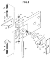
- a picking apparatus 1 in a rapier loom comprises, as illustrated in Figs. 1 to 4, first and second gripping bodies 2, 3, a block shaped slider 4 and a driving means 5. These elements 2, 3, 4 and 5 are incorporated in first and second brackets 6, 7. That is, the first bracket 6 is attached to a loom frame, not shown, between fingers 8a, 8b of a weft selection device and a woven cloth 9.
- the bracket 6 has a slider shaft provided vertically at an open end of the front portion thereof and supports the slider 4 vertically movably along the slider shaft 10.
- the slider 4 has a gripper 11 incorporated therewith at the front central portion thereof.
- the gripper 11 has a movable blade 12 at the side of a woven cloth 9.
- the movable blade 12 and a fixed blade 13 described later constitute a yarn cutter 14.
- the slider 4 is connected to one end of a cam lever 17 via a slide piece 15 horizontally movable in a groove formed in horizontal direction at the side of the weft selection device and a connecting pin 16 inserted into the slide piece 15.
- the cam lever 17 is substantially L shaped and rotatably supported by the first bracket 6 about a lever shaft 18 at the base end thereof.
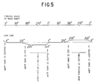
- the cam lever 17 is urged clockwise in Fig. 1 by a drawing spring 19 and is positioned by a contour of a rotatable plate like cam 22 together with cam shaft 21 via a cam ball 20 provided at the central portion of the lever 17.
- the contour curve line of the cam 22 is determined as illustrated in Fig. 5 relative to the turning angle of the main shaft of the loom.
- the cam shaft 21 corresponds to a color pattern 1 x 1 in which two yarns are successively picked one after the other according to the first embodiment of the present invention.
- the cam shaft 21 rotates in synchronous with the main shaft of the loom and the reduction gear ratio of the cam shaft 21 relative to the main shaft of the loom is set to be 1 : 2.
- the cam lever 17 and the cam 22 constitute the driving means 5.
- the second bracket 7 is attached to the front end surface and holds the two gripping bodies 2, 3 so that the two gripping bodies 2, 3 are movable up and down toward guide holes 27, 28 of the second bracket 7.
- the gripping bodies 2, 3 are integrated with guide shafts 23, 24 and confronted vertically with each other with interposing the gripper 11 of the slider 4 at the middle portion thereof.
- Compressed springs 25, 26 are wound around the guide shafts 23, 24 to urge the gripping bodies 2, 3 toward the gripper 11 so that the gripping bodies 2, 3 always contact the gripper 11 of the middle position.
- the upper guide shaft 23 is restricted to move downward by a stop ring 29 attached to the upper end thereof and the lower guide shaft 24 is restricted to move upward by a stop ring 30 attached to the lower end thereof.
- a yarn guide 32 is attached to the side surface of the second bracket 7, i.e., at the side of the fingers 8a, 8b of the weft selection device.
- the yarn guide 32 has a yarn introduction slit 33 at the side of a let-off motion of the loom.
- the yarn guide 32 is attached to the second bracket 7 so that the yarn introduction slit 33 is horizontally flush with the open portion defined between the gripping bodies 2, 3 and the gripper 11 of the slider 4.
- the second bracket 7 is opened at the front side thereof in the same size as the open end of the first bracket 6 and integrated with the fixed blade bracket 31 at the opend end thereof.
- the fixed blade bracket 31 has the fixed blade 13 having a V-shaped opening at the inside front portion thereof and attached to the side surface of the bracket 7 at the side of the woven cloth 9.
- the fixed blade 13 contacts the movable blade 12 so as to bring about the shear forth to affect the weft yarn.
- the first bracket 6 is positioned, as illustrated in Fig. 6, in the manner that the yarn cutter 14 is close to the selvage of the woven cloth 9 so that the yarn introduction slit 33 is flush with the extension line of the cloth fell of the woven cloth 9. Consequently, the first and the second gripping bodies 2, 3 are movable up and down at the position where they cross the extension line of the cloth fell.
- the picking apparatus 1 confronts a reed 35 on a slay 34 and the part of the picking apparatus 1 between the yarn guide 32 and the fixed blade bracket 31 confronts the opening of the reed 35.
- the cam lever 17 swings in proportion to the contour of the cam 22 to thereby move the slider 4 up and down whereby the gripper 11 of the slider 4 moves up and down between the first and the second gripping bodies 2, 3.
- the gripping bodies 2, 3 moves up and down against the resilience force of the compressed springs 25, 26 while following the vertical motion of the gripper 11.
- the first gripping body 2 keeps contact with the the gripper 11 while there is defined an open portion beween the second gripping body 3 and the gripper 11.
- the second gripping body 3 keeps contact with the the gripper 11 while there is defined an open portion beween the first gripping body 2 and the gripper 11.
- the open portion defined therebetween is positioned on the extension line of the cloth fell.
- the gripper 11 is brought into contact with both the first and the second gripping bodies 2, 3.
- the yarn cutter 14 can cut the weft yarn gripped by the gripper 11 and the first gripping body 2 or by the gripper 11 and the second gripping body 3.
- the slider 4 is, at the middle position thereof, in the state where the gripper 11 is brought inro contact with the first and the second gripping bodies 2, 3 and two weft yarns 9a, 9b can be gripped therebetween as illustrated in Fig. 6.
- Figs. 7 (1) to (12) show a series of picking operations of the picking apparatus relative to an crank angle in accordance with the color pattern 1 x 1.
- Figs. 7 (1) to (12) correspond to operating stages (1) to (12).
- the weft yarns 9a, 9b are picked one after the other to form 1 x 1 weaving texture.
- a second embodiment of the picking apparatus in a rapier loom according to a second embodiment will be described with reference to Figs. 8 to 10.
- the two color alternate two pick weave (a color pattern 2 x 2) or the two color alternate pick weave (a color pattern 2 x 1) is carried out, namely, one of the at least two weft yarns 9a, 9b is successively picked.
- the two color alternate two pick weave means that the weft yarn 9a is successively picked two times and then the weft yarn 9b is successively picked two times in one cycle of the picking operation.
- the yarn cutter 14 is composed of the movable blade 12 fixed to the gripper 11 of the slider 4 and the fixed blade 13 fixed to the fixed blade bracket 31.
- Figs. 8 (1) to (5) show a series of picking operations according to the second embodiment of the picking apparatus in which each figure shows location of the gripper 11 and the gripping bodies 2, 3 on each operating stage.
- the slider 4 moves, as illustrated in Figs. 8(1) to 8(5), up and down in five stages by the cam 22 having the contour different from the cam in Fig. 5 at the given timing.
- the stages (2) to (4) are a middle position.
- the weft yarns 9a, 9b are gripped by the gripper 11 and the first and the second gripping bodies 2, 3.
- any of the weft yarns 9a, 9b can be cut. That is, the weft yarn 9b is cut when the operation moves from the stages (1) to (3) to the stage (4) or (5) and the weft yarn 9a is cut when the operation moves from the stages (5) to (3) to the stage (2) or (1).
- Figs. 9 (1) to (17) show a series of picking operations according to a color pattern 2 x 2 in which each figure shows each operating stage.
- the reduction gear ratio of the cam shaft 21 relative to the main shaft of the loom is set to be 1 : 4.
- the weft yarn 9b is picked successively two times and beaten. After beaten, the weft yarn yarn 9b is cut at the stages (5) and (11).
- the weft yarn 9a is picked successively two times and beaten and cut at the stages (13) and (3).
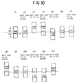
- Figs. 10 (1) to (13) show a series of picking operations in accordance with two color alternate two pick x one pick weave (a color pattern 2 x 1) in which each figure shows location of the gripper 11, the gripping bodies 2, 3 and the weft yarns 9a, 9b on each operating stage.
- the reduction gear ratio of the cam shaft 21 relative to the main shaft of the loom is set to be 1 : 3.
- the two color alternate two pick x one pick weave (the color pattern 2 x 1) means that the weft yarn 9b is successively picked two times then the weft yarn 9a is picked one time in one cycle of the picking operation.
- Fig. 10 (1) to (13) show a series of picking operations in accordance with two color alternate two pick x one pick weave (a color pattern 2 x 1) in which each figure shows location of the gripper 11, the gripping bodies 2, 3 and the weft yarns 9a, 9b on each operating stage.
- the reduction gear ratio of the cam shaft 21 relative to the main shaft of the loom is set to be 1
- the picking apparatus 1 repeates the operation successively so as to grip the weft yarn yarns 9a, 9b, guide the weft yarns 9a, 9b to the open portions in response to the cutting operation and the beating operation.
- the picking operation according to the second embodiment differs from the first embodiment in that when one of the weft yarns 9b, e.g. is picked successively two times, the first picked weft yarn 9b is cut by the gripper 11's moving to the stage (2) at crank angle about 30° for next picking while the other weft yarn 9a is gripped. After this, the slider 4 moves to its middle position before the weft yarn 9b is picked at second time. Whereupon, the slider 4 is positioned at its middle position at the stage (3) but may be positioned at the stage of (2) or (4).
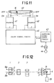
- a picking apparatus of a rapier loom according to a third embodiment of the present invention will be described with reference to Figs. 11 to 14.
- the driving means 5 is composed of, as illustrated in Fig. 11, first and second solenoids 41, 42 and the like.
- the yarn cutter 14 is, as illustrated in Fig. 12, provided separately from the picking apparatus 1 whereby the weft yarns can be picked in accordance with two color free pick weave (a color pattern AT WILL), namely, the weft yarns 9a, 9b can be picked at will.
- the yarn cutter 14 is disposed at the portion adjacent to the woven cloth 9 and opposed to the picking apparatus 1.
- the yarn cutter 14 is connected to a driving portion 39 so as to cut the weft yarn one time before the weft yarn is picked, i.e. during the period after the beating operation and before the picking operation.
- the slider 4 is in its middle position at the start of the picking opeation to grip both the weft yarns 9a, 9b and moves uppermost or lowest at the beating operation to thereby form the open portion for receiving the picked weft yarn 9a or 9b.
- the slider 4 is set to be positioned at its middle position at cranks angle between 6 o to 126 o .
- the slider 4 is positioned at the upper or the lower position except that period mentioned just above so that the slider 4 is ready for receiving the weft yarns 9a or 9b to be beaten.
- the yarn cutter 14 operates at crank angle about 30 o to cut any of the weft yarns 9a or 9b.
- the solenoids 41, 42 are connected to the lever 40 at the distal ends of the rods thereof.
- a connecting pin 16 is fixed on the lever 40 at the position displaced from the center of the lever 40.
- Positions 1, 2, 3 of the connecting pin 16 as illustrated in Fig. 11 correspond to positions 1, 2, 3 of the gripper 11 of the slider 4.
- the slider 4 can move to three stages as illustrated in Fig. 13 on the basis of the on or off control of the two solenoids 41, 42.
- output patterns of switching signals K1 to K3 is previously input and stored in a switching signal output circuit 43.
- the switching signal output circuit 43 receives a crank angle signal during weaving operation from an encoder connected to a main shaft 44 of the loom and provides the corresponding switching signals successively to an on-off control circuit 46 during the output period of the switching signals.
- the on-off control circuit 46 selectively turns on or off the solenoid 41 or 42 in response to the switching signals K1 to K3 to thereby place the the lever 40 horizontally or incline the lever 40 in any direction so that the hight of the connecting pin 16 is adjusted to three stages.
- a picking apparatus of a rapier loom according to a fourth embodiment will be described with reference to Figs. 15 and 16.
- the slider 4 is electrically and directly driven so that the weft yarns 9a, 9b can be picked at will. in accodance with the two color free pick weave.
- the switching output circuit 43 operates in the same way as that of the third embodiment.
- a switching circuit 48 in a rotation control circuit 47 receives driving signals S1 to S3 corresponding to the switching signals K1 to K3 from a setting circuit 49 upon reception of the switching signals K1 to K3 from the switching signal output circuit 43 and provides the driving signals S1 to S3 to a driving circuit 50.
- the drivng cirucit 50 drives a pulse motor 51 which moves the slider 4 up and down in correspondence with the three positions 1, 2 or 3 as illustrated in Fig. 12.
- the rotary motion of the pulse motor 51 is changed to the vertical motion of the connecting pin 16 of a slider 54 along a rail 55 by a rack 52 and a pinion 53.
- the picking apparatuses of the rapier loom according to the first to fourth embodiments set forth above relate to the two-color yarns but may be utilized for the four-color weft yarns.
- two picking apparatuses are disposed in two stages at upper and lower positions and the two picking apparatuses per se are moved up and down in response to the selected weft yarn so that the picking apparatuses are positioned for picking operation.
- the driving means for driving the apparatuses comprises the cam, the lever mechanism and the rotation control device of the motor as employed in the first to fourth embodiments.
- the open portions defined between the gripper 11 and the first and the second gripping bodies 2, 3 are positioned at the extension line of the cloth fell so that each picking apparatus can carry out the necessary operation.
- the gripping bodies 2, 3 are movable linearly up and down according to the first to the fourth embodiments, the gripping bodies may be movable circularly up and down.
- the gripping bodies 2, 3 may be provided at the distal ends of the two levers which swing about one point.
- the gripper 11 of the slider 4 and the gripping bodies 2, 3 are positioned to cross the extension line of the cloth fell at the gripping surfaces thereof to minimize the loss of the weft yarn.
- the gripping surfaces of the grippe 11 of the slider 4 and the gripping bodies 2, 3 may be positioned slightly closer to the winding side or the let off side than the extension line of the cloth fell.
- a yarn pusher 36 is provided at the slay 34 so that the weft yarn end is forcibly guided to the open portion defined between the gripper and the girpping bodes 2, 3.
- the yarn introduction slit 33 of the yarn guide 32 may form a hook shaped groove 33a as illustrated in Fig. 17 so that the weft yarn 9a or 9b enters the groove 33a when they are gripped.
- the weft yarn 9a or 9b enters the groove 33a, the weft yarn 9a or ob can not slip out thereof even if the forward force is applied thereto so that the weft yarn 9a or 9b is gripped and cut with assuracne.
Landscapes
- Engineering & Computer Science (AREA)
- Textile Engineering (AREA)
- Looms (AREA)
Claims (7)
- Appareil de chasse (1) dans un métier à tisser à griffes, comprenant un coupoir de fil (14) agissant pour couper un fil de trame (9a ou 9b) avant que le fil de trame (9a ou 9b) ne soit chassé, une coulisse (4) et des moyens d'entraînement (5),
caractérisé en ce que
des premier et deuxième corps de prise (2, 3) opposés sont respectivement disposés entre des premier et deuxième doigts (8a, 8b) d'un dispositif de sélection de fil de trame et un coupoir de fil (14), les premier et deuxième corps de prise (2, 3) déplaçables vers le haut et vers le bas et étant rappelés en direction de leur position médiane, pour se faire face ;
la coulisse comporte une pince (11) déplaçable vers le haut et vers le bas, entre les premier et deuxième corps de prise (2, 3), la pince (11) pouvant venir au contact à la fois des premier et deuxième corps de prise (2, 3) lorsqu'il est disposé dans la position médiane entre les premier et deuxième corps de prise (2, 3), et pouvant venir au contact de l'un des corps de prise (2, 3), de manière qu'une partie ouverte est définie entre la pince (11) de la coulisse (4) et l'autre corps de prise (3 ou 2), lorsqu'il est disposé sur l'un des corps de prise (2, 3); et
lesdits moyens d'entraînement (5) peuvent déplacer la coulisse (4) vers l'un des corps de prise (2 ou 3) selon un motif de couleur lors de l'opération de battage des fils de trame (9a, 9b) et pouvant amener la coulisse (4) dans la position médiane entre les premier et deuxième corps de prise (2, 3), au début de l'opération de chasse du fil de trame (9a, 9b). - Appareil de chasse (1) d'un métier à tisser à griffes selon la revendication 1, dans lequel le coupoir de fil (14) comprend une lame déplaçable (12) prévue sur la surface latérale de la coulisse (4) et une lame fixe (13) prévue sur un support de lame (31) fixe, pour porter les corps de prise (2, 3).
- Appareil de chasse (1) d'un métier à tisser à griffes selon la revendication 1, comprenant en outre un guide-fil (32) prévu à côté des premier et deuxième corps de prise (2,3), le guide-fil (32) ayant une fente d'introduction de fil (33) disposée adjacente à la pince (11) de la coulisse (4).
- Appareil de chasse (1) d'un métier à tisser à griffes selon la revendication 1, dans lequel les moyens d'entraînement (5) comprennent une came (22) qui entraîne la coulisse (4) et peut tourner en synchronisme avec un mouvement rotatif du métier à tisser à griffes et un levier (17) pouvant déplacer la coulisse (4) vers le haut et vers le bas.
- Appareil de chasse (1) d'un métier à tisser à griffes selon la revendication 1, dans lequel les moyens d'entraînement (5) comprennent un circuit de production de signaux de commutation (43) servant à produire des signaux de commutation en synchronisme avec la rotation d'un arbre principal (44) du métier à tisser à griffes, des premier et deuxième électro-aimant (41, 42) activés à la réception des signaux de commutation, et un levier (40) ayant ses deux extrémités reliées aux premier et deuxième électro-aimant (41, 42) et pouvant s'interverrouiller avec la coulisse (4) entre les deux extrémités.
- Appareil de chasse (1) d'un métier à tisser à griffes selon la revendication 1, dans lequel les moyens d'entraînement (5) comprennent un circuit de production de signaux de commutation (43) pour produire des signaux de commutation en synchronisme avec la rotation d'un arbre principal (44) du métier à tisser à griffes, un moteur à impulsions (51) commandé à la réception des signaux de commutation, et une crémaillère (52) et un pignon (53) respectivement déplacés en va-et-vient par le moteur à impulsions (51).
- Appareil de chasse (1) d'un métier à tisser à griffes selon la revendication 1, dans lequel les premier et deuxième corps de prise (2, 3), la coulisse (4) et les moyens d'entraînement (5) sont disposés en plusieurs étages en suivant la chasse d'un nombre paire de deux ou plusieurs trames de couleur.
Applications Claiming Priority (2)
| Application Number | Priority Date | Filing Date | Title |
|---|---|---|---|
| JP258999/89 | 1989-10-04 | ||
| JP1258999A JP2762132B2 (ja) | 1989-10-04 | 1989-10-04 | レピア織機用のよこ入れ装置 |
Publications (2)
| Publication Number | Publication Date |
|---|---|
| EP0421349A1 EP0421349A1 (fr) | 1991-04-10 |
| EP0421349B1 true EP0421349B1 (fr) | 1994-12-14 |
Family
ID=17327953
Family Applications (1)
| Application Number | Title | Priority Date | Filing Date |
|---|---|---|---|
| EP90118873A Expired - Lifetime EP0421349B1 (fr) | 1989-10-04 | 1990-10-02 | Dispositif de pince dans un métier à tisser à aiguilles |
Country Status (5)
| Country | Link |
|---|---|
| US (1) | US5090456A (fr) |
| EP (1) | EP0421349B1 (fr) |
| JP (1) | JP2762132B2 (fr) |
| KR (1) | KR920009214B1 (fr) |
| DE (1) | DE69015091T2 (fr) |
Families Citing this family (8)
| Publication number | Priority date | Publication date | Assignee | Title |
|---|---|---|---|---|
| DE19806953C2 (de) * | 1998-02-19 | 2000-03-02 | Dornier Gmbh Lindauer | Schneideinrichtung in Webmaschinen |
| CN102277679B (zh) * | 2011-06-20 | 2013-02-27 | 陈仲纪 | 一种剑杆织机的省料剪纬装置 |
| BE1019807A3 (nl) | 2011-07-12 | 2012-12-04 | Picanol | Inrichting en werkwijze voor het klemmen van een inslagdraad. |
| US9416467B2 (en) | 2012-01-24 | 2016-08-16 | Nike, Inc. | Three-dimensional weaving system |
| CN104126040B (zh) * | 2012-01-24 | 2017-06-09 | 耐克创新有限合伙公司 | 编织修整装置 |
| KR101894620B1 (ko) | 2012-01-24 | 2018-09-03 | 나이키 이노베이트 씨.브이. | 간헐적 위빙 스플라이서 |
| BE1024401B1 (nl) | 2016-07-04 | 2018-02-13 | Picanol N.V. Naamloze Vennootschap | Inrichting voor het klemmen van inslagdraden |
| US11299827B2 (en) | 2018-05-17 | 2022-04-12 | James Tolle | Nanoconductor smart wearable technology and electronics |
Family Cites Families (6)
| Publication number | Priority date | Publication date | Assignee | Title |
|---|---|---|---|---|
| DE1710291B2 (de) * | 1967-04-22 | 1973-10-04 | Fa. S. Lentz, 4060 Viersen | Einrichtung zum Schneiden und Klemmen von Schußfäden an Greiferwebmaschinen |
| CH520217A (de) * | 1971-02-17 | 1972-03-15 | Fischer Ag Brugg Georg | Schussfadenschneide- und -Klemmvorrichtung an einer Webmaschine |
| CH540365A (it) * | 1971-06-21 | 1973-08-15 | Somet Soc Mec Tessile | Dispositivo di taglio dei fili di trama per telai di tessitura |
| AT317801B (de) * | 1972-09-18 | 1974-09-10 | Voest Ag | Schußfadenschere für Webmaschinen |
| NL8600857A (nl) * | 1986-04-03 | 1987-11-02 | Picanol Nv | Werkwijze voor het klemmen, vasthouden en presenteren van inslagdraden bij grijperweefmachines en inrichting hiertoe aangewend. |
| DE3812960A1 (de) * | 1987-10-06 | 1989-04-20 | Textilma Ag | Greiferwebmaschine |
-
1989
- 1989-10-04 JP JP1258999A patent/JP2762132B2/ja not_active Expired - Lifetime
-
1990
- 1990-09-28 KR KR1019900015507A patent/KR920009214B1/ko not_active Expired
- 1990-10-02 EP EP90118873A patent/EP0421349B1/fr not_active Expired - Lifetime
- 1990-10-02 DE DE69015091T patent/DE69015091T2/de not_active Expired - Fee Related
- 1990-10-04 US US07/593,014 patent/US5090456A/en not_active Expired - Fee Related
Also Published As
| Publication number | Publication date |
|---|---|
| EP0421349A1 (fr) | 1991-04-10 |
| DE69015091D1 (de) | 1995-01-26 |
| DE69015091T2 (de) | 1995-04-27 |
| KR910008199A (ko) | 1991-05-30 |
| KR920009214B1 (ko) | 1992-10-15 |
| JPH03124844A (ja) | 1991-05-28 |
| JP2762132B2 (ja) | 1998-06-04 |
| US5090456A (en) | 1992-02-25 |
Similar Documents
| Publication | Publication Date | Title |
|---|---|---|
| EP0421349B1 (fr) | Dispositif de pince dans un métier à tisser à aiguilles | |
| US5158119A (en) | Selvedge forming device for shuttleless looms with linear motor control system | |
| CA2996462A1 (fr) | Metier a tisser presentant un dispositif ainsi qu'un procede de maintien, d'amenee et d'insertion de fils de trame dans une foule | |
| US3951177A (en) | Devices for folding into the warp shed both ends of a weft thread in a fabric made by a shuttleless loom having a continuous weft supply mechanism | |
| EP0240075B1 (fr) | Procédé et dispositif pour le pinçage, l'accrochement et la présentation de fils de trame dans le métiers à griffes | |
| JPS63303150A (ja) | 杼なし織機で生産される織物において軽量かつ薄厚の曲げ込まれた耳部を形成する機械 | |
| ES8103788A1 (es) | Perfeccionamientos introducidos en las instalaciones para elaccionamiento forzoso del dispositivo de pinzado de organos de insercion de la trama en telares sin lanzadera | |
| EP1251196B1 (fr) | Dispositif pour présenter les fils de trame dans un métier à tisser à lances | |
| EP0379703A1 (fr) | Mécanisme de commande pour la sélection de fils de trame dans les métiers à pinces | |
| US4781226A (en) | Driving and control mechanism for clamping, presentation and fastening of weft threads in gripper weaving looms | |
| JPH09268450A (ja) | 織機における捨耳形成方法及び装置 | |
| US2578205A (en) | Gripper-shuttle loom | |
| US7044174B2 (en) | Method and device for opening a gripper clip of a mechanical-loom gripper | |
| US4132249A (en) | Weft selection and retention mechanism for shuttleless looms | |
| US5080143A (en) | Selvedging device with threading nozzle and tuck-in needle | |
| EP1052318B1 (fr) | Dispositif d'annulation de l'insertion pour un métier à tisser | |
| TWI732251B (zh) | 用於無梭子紡織機的緯紗切割裝置 | |
| US3376900A (en) | Looms operating with multi-color stationary weft supplies | |
| CA1318830C (fr) | Methode de confection de joint integre de toile sans fin et machine correspondante | |
| US4640315A (en) | Projectile weaving machine | |
| US2714397A (en) | Device for shifting pile warp crossings toward fell | |
| US3528460A (en) | Detecting means for weft selecting means | |
| GB1273022A (en) | Improvements in picking mechanism for looms for weaving | |
| GB245791A (en) | Improvements in or relating to looms for weaving pile fabrics | |
| JP2569688B2 (ja) | 無杼織機におけるミス糸除去装置 |
Legal Events
| Date | Code | Title | Description |
|---|---|---|---|
| PUAI | Public reference made under article 153(3) epc to a published international application that has entered the european phase |
Free format text: ORIGINAL CODE: 0009012 |
|
| AK | Designated contracting states |
Kind code of ref document: A1 Designated state(s): BE CH DE FR GB IT LI |
|
| 17P | Request for examination filed |
Effective date: 19910912 |
|
| 17Q | First examination report despatched |
Effective date: 19931001 |
|
| GRAA | (expected) grant |
Free format text: ORIGINAL CODE: 0009210 |
|
| AK | Designated contracting states |
Kind code of ref document: B1 Designated state(s): BE CH DE FR GB IT LI |
|
| ITF | It: translation for a ep patent filed | ||
| REF | Corresponds to: |
Ref document number: 69015091 Country of ref document: DE Date of ref document: 19950126 |
|
| ET | Fr: translation filed | ||
| PGFP | Annual fee paid to national office [announced via postgrant information from national office to epo] |
Ref country code: GB Payment date: 19950925 Year of fee payment: 6 |
|
| PGFP | Annual fee paid to national office [announced via postgrant information from national office to epo] |
Ref country code: FR Payment date: 19951010 Year of fee payment: 6 |
|
| PGFP | Annual fee paid to national office [announced via postgrant information from national office to epo] |
Ref country code: DE Payment date: 19951012 Year of fee payment: 6 |
|
| PLBE | No opposition filed within time limit |
Free format text: ORIGINAL CODE: 0009261 |
|
| STAA | Information on the status of an ep patent application or granted ep patent |
Free format text: STATUS: NO OPPOSITION FILED WITHIN TIME LIMIT |
|
| PGFP | Annual fee paid to national office [announced via postgrant information from national office to epo] |
Ref country code: CH Payment date: 19951027 Year of fee payment: 6 |
|
| PGFP | Annual fee paid to national office [announced via postgrant information from national office to epo] |
Ref country code: BE Payment date: 19951110 Year of fee payment: 6 |
|
| 26N | No opposition filed | ||
| PG25 | Lapsed in a contracting state [announced via postgrant information from national office to epo] |
Ref country code: GB Effective date: 19961002 |
|
| PG25 | Lapsed in a contracting state [announced via postgrant information from national office to epo] |
Ref country code: LI Effective date: 19961031 Ref country code: CH Effective date: 19961031 Ref country code: BE Effective date: 19961031 |
|
| BERE | Be: lapsed |
Owner name: TSUDAKOMA CORP. Effective date: 19961031 |
|
| GBPC | Gb: european patent ceased through non-payment of renewal fee |
Effective date: 19961002 |
|
| REG | Reference to a national code |
Ref country code: CH Ref legal event code: PL |
|
| PG25 | Lapsed in a contracting state [announced via postgrant information from national office to epo] |
Ref country code: FR Effective date: 19970630 |
|
| PG25 | Lapsed in a contracting state [announced via postgrant information from national office to epo] |
Ref country code: DE Effective date: 19970701 |
|
| REG | Reference to a national code |
Ref country code: FR Ref legal event code: ST |
|
| PG25 | Lapsed in a contracting state [announced via postgrant information from national office to epo] |
Ref country code: IT Free format text: LAPSE BECAUSE OF NON-PAYMENT OF DUE FEES Effective date: 20051002 |