EP0421492B1 - Ligne de production pour stators de moteur électrique montés sur palette et procédé de fabrication de tels stators - Google Patents
Ligne de production pour stators de moteur électrique montés sur palette et procédé de fabrication de tels stators Download PDFInfo
- Publication number
- EP0421492B1 EP0421492B1 EP90125434A EP90125434A EP0421492B1 EP 0421492 B1 EP0421492 B1 EP 0421492B1 EP 90125434 A EP90125434 A EP 90125434A EP 90125434 A EP90125434 A EP 90125434A EP 0421492 B1 EP0421492 B1 EP 0421492B1
- Authority
- EP
- European Patent Office
- Prior art keywords
- stator
- stators
- pallet
- production line
- working stations
- Prior art date
- Legal status (The legal status is an assumption and is not a legal conclusion. Google has not performed a legal analysis and makes no representation as to the accuracy of the status listed.)
- Expired - Lifetime
Links
- 238000004519 manufacturing process Methods 0.000 title claims description 15
- 238000000034 method Methods 0.000 title claims description 9
- 238000012545 processing Methods 0.000 title claims description 7
- 238000004804 winding Methods 0.000 claims description 15
- 238000012546 transfer Methods 0.000 description 6
- 230000015572 biosynthetic process Effects 0.000 description 2
- 238000010276 construction Methods 0.000 description 1
- 238000009413 insulation Methods 0.000 description 1
- 238000012986 modification Methods 0.000 description 1
- 230000004048 modification Effects 0.000 description 1
- 230000000452 restraining effect Effects 0.000 description 1
- 238000005476 soldering Methods 0.000 description 1
- 238000012360 testing method Methods 0.000 description 1
- 238000011144 upstream manufacturing Methods 0.000 description 1
Images

Classifications
-
- H—ELECTRICITY
- H02—GENERATION; CONVERSION OR DISTRIBUTION OF ELECTRIC POWER
- H02K—DYNAMO-ELECTRIC MACHINES
- H02K15/00—Processes or apparatus specially adapted for manufacturing, assembling, maintaining or repairing of dynamo-electric machines
-
- Y—GENERAL TAGGING OF NEW TECHNOLOGICAL DEVELOPMENTS; GENERAL TAGGING OF CROSS-SECTIONAL TECHNOLOGIES SPANNING OVER SEVERAL SECTIONS OF THE IPC; TECHNICAL SUBJECTS COVERED BY FORMER USPC CROSS-REFERENCE ART COLLECTIONS [XRACs] AND DIGESTS
- Y10—TECHNICAL SUBJECTS COVERED BY FORMER USPC
- Y10T—TECHNICAL SUBJECTS COVERED BY FORMER US CLASSIFICATION
- Y10T29/00—Metal working
- Y10T29/53—Means to assemble or disassemble
- Y10T29/5313—Means to assemble electrical device
- Y10T29/53143—Motor or generator
- Y10T29/53161—Motor or generator including deforming means
-
- Y—GENERAL TAGGING OF NEW TECHNOLOGICAL DEVELOPMENTS; GENERAL TAGGING OF CROSS-SECTIONAL TECHNOLOGIES SPANNING OVER SEVERAL SECTIONS OF THE IPC; TECHNICAL SUBJECTS COVERED BY FORMER USPC CROSS-REFERENCE ART COLLECTIONS [XRACs] AND DIGESTS
- Y10—TECHNICAL SUBJECTS COVERED BY FORMER USPC
- Y10T—TECHNICAL SUBJECTS COVERED BY FORMER US CLASSIFICATION
- Y10T29/00—Metal working
- Y10T29/53—Means to assemble or disassemble
- Y10T29/5313—Means to assemble electrical device
- Y10T29/53261—Means to align and advance work part
-
- Y—GENERAL TAGGING OF NEW TECHNOLOGICAL DEVELOPMENTS; GENERAL TAGGING OF CROSS-SECTIONAL TECHNOLOGIES SPANNING OVER SEVERAL SECTIONS OF THE IPC; TECHNICAL SUBJECTS COVERED BY FORMER USPC CROSS-REFERENCE ART COLLECTIONS [XRACs] AND DIGESTS
- Y10—TECHNICAL SUBJECTS COVERED BY FORMER USPC
- Y10T—TECHNICAL SUBJECTS COVERED BY FORMER US CLASSIFICATION
- Y10T29/00—Metal working
- Y10T29/53—Means to assemble or disassemble
- Y10T29/5313—Means to assemble electrical device
- Y10T29/53265—Means to assemble electrical device with work-holder for assembly
Definitions
- the invention relates to a production line for pallet-mounted electric motor stators.
- stators lie directly on pallets on conveyor belts which move along lines.
- the various working stations are provided at the sides of these lines. These stations include the stations for slot insulation, mounting the shoulders and mounting the terminals on them, winding formation, wire end termination, terminal soldering, coil baking, and stator electrical testing.
- the stators On reaching one of these stations, the stators must be removed from the conveyor belt and positioned in the working station, after which the stator is again returned to the line for feeding to the next station.
- Document GB-A-2145355 relates to an apparatus and method for the automatic production of armatures for small electric motors.
- the armatures are clamped in work piece holders and are moved to successive stations of the apparatus by a conveyor belt.
- the work piece holders are raised in relation to the conveyor belt by positioning a locking bolt and are held in the working position.
- the armatures are mounted on the work piece holders with vertical axis and the work piece holder is not provided with means arranged to temporarily receive the ends of wire windings.
- the invention provides a line in which the stators are mounted with their axis horizontal and perpendicular to the direction of travel of the line on cradle-shape portions of pallets which move with the conveyor belt.
- the pallet is raised together with the stator so that it can be positioned in relation to the machine which is to carry out the necessary work.
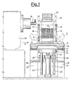
- Figure 1 is a cross-section of a transfer line for the transfer of pallets which carry stators mounted thereon with their axis extending in a horizontal direction, wherein said cross-section is made at a processing station and at respective devices for positioning the pallets in relation to said station.
- Figure 2 is a view in the direction of the arrow A of Fig. 1.
- Figure 1 and 2 show a stator 10 of conventional type, mounted, with its axis extending in a horizontal direction, on a cradle-shape portion of a cylindrical hollow body 11 anchored at its lower portion on a base 12.
- the base 12 and the body 11 form the pallet which slides on the belts 13 of the transfer line.
- Stator 10 is mounted on the body 11, at the side of which there are provided appendices 16 intended to ensure the temporary anchorage of the ends of the wires 17 after windings 18 have been formed on the slots of the stator.
- Figure 1 shows the station for forming the windings 18, which is disposed at the side of the line 13 and operates along a horizontal axis.
- a needle 19 is disposed eccentrically and is able to provide windings without the aid of the conventional forming shoes.
- This construction of the eccentric needle has formed the subject-matter of the nursery patent No. 1200443 of April 2, 1985, in the name of the present Applicant.
- stator 10 is disposed on the pallet, with its axis extending in a horizontal direction.
- stator 10 could have been disposed with its axis extending vertically on another pallet, in which case a simple device (not shown) would produce rotation and arrangement of the stator into the present position on the cylindrical hollow body 11.
- stator travels on the pallet along the line always keeping this position with the axis extending horizontally, and all the processing stations, and not only the winding station described herein, are arranged in such a manner as to able to work thereon in such position.
- stator working stations Since not all the stator working stations can be positioned at the level of the advancing stator, it is necessary to be able to raise the pallet with the stator on it vertically from the conveyor belt 13 in order to reach a position corresponding to the working station itself.
- the device which produces the vertical transfer of the pallet is formed, by way of example, by a cylinder 22 whose piston rod 23 is rigidly connected to a fork 24 provided with bars 25 which slide in guides 26 of a support 28 fixed to the frame 27 on which the conveyer belts 27 slide. Cylinder 22 also is rigidly connected to the support 28 screwed to the frame 27.
- cylinder 22 is actuated in the opposite direction and the pallet returns to rest on the conveyer belts 13 in order to be transferred into the succeeding station which usually is the termination station in which the ends of the wires 17 are manipulated for the definitive anchorage to the terminals of the stator and then the exceeding portions are cut away.
Landscapes
- Engineering & Computer Science (AREA)
- Manufacturing & Machinery (AREA)
- Power Engineering (AREA)
- Manufacture Of Motors, Generators (AREA)
Claims (10)
- Ligne de production de stators de moteurs électriques, laquelle ligne de production comporte une pluralité de stations de travail sur stator (20), ainsi qu'un moyen de convoyage à bande transporteuse (13) disposé à proximité des stations de travail sur stator (20) pour faire avancer les stators (10) de station de travail en station de travail; une pluralité de palettes (12) supportant individuellement lesdits stators (10) placés sur lesdites palettes pendant le déplacement desdits stators de station de travail en station de travail (20); ladite ligne de production étant caractérisée par le fait que le processus de production est appliqué aux stators (10) pendant qu'ils sont montés sur leurs palettes respectives (12), lesquelles palettes comportent un élément creux (11) ayant une partie en forme de berceau à l'intérieur de laquelle le stator (10) est placé avec son axe en position horizontale et perpendiculaire à la direction de déplacement du moyen de convoyage à bande transporteuse.
- Ligne de production de stators de moteurs électriques selon la revendication 1, caractérisée par le fait que des appendices (16) sont prévus, qui saillent desdites palettes (12) pour recevoir temporairement les extrémités des enroulements de fil (17) bobinés sur le stator (10) dans une des stations de travail sur stator (20).
- Ligne de production de stators de moteurs électriques selon la revendication 1, caractérisée par le fait qu'on a prévu des moyens (30) dans les stations de travail sur stator (20) pour fixer de manière rigide les stators (10) sur les palettes (12).
- Ligne de production de stators de moteurs électriques selon la revendication 1, caractérisée par le fait qu'on a prévu des moyens mécaniques (22, 29) à proximité des stations de travail sur stator (20), pour lever les ensembles palette (12)/stator (10) de la bande transporteuse (13), afin d'imprimer une translation auxdits ensembles palette (12)/stator (10) de façon à ce que les stators (10) respectifs soient placés dans les positions correspondant aux stations de travail sur stator (20) réparties tout le long de la ligne de production.
- Ligne de production de stators de moteurs électriques selon la revendication 4, caractérisée par le fait que lesdits moyens mécaniques (22, 29) comprennent un vérin (22) placé en-dessous du moyen de convoyage à bande transporteuse (13), une tige (23) actionnée par le vérin, et une fourche (24) connectée de manière rigide à ladite tige (23) et qui peut s'engager sous lesdites palettes (12) pour imprimer un mouvement de translation auxdites palettes (12) par actionnement du vérin (22).
- Ligne de production selon la revendication 4 et selon la revendication 5, caractérisée par le fait qu'elle comporte une paire de bras distants l'un de l'autre (25), ledit moyen de convoyage à bande transporteuse (13) comporte un bâti (28) ayant des guides (26) à l'intérieur, lesdits bras (25) de la fourche (24) coulissant à l'intérieur desdits guides (26) du bâti (28) du moyen de convoyage à bande transporteuse (13), et ledit vérin (22) étant fixé de manière rigide audit bâti (28).
- Procédé de traitement de stators de moteurs électriques le long d'une ligne de production comprenant une pluralité de stations de travail sur stator (20) opérant dans ladite ligne de production, et un moyen de convoyage à bande transporteuse (13) disposé à proximité des stations de travail sur stator (20) pour faire avancer les stators (10) de station de travail en station de travail; ledit procédé étant caractérisé par les étapes suivantes:(a) chaque stator (10) est supporté sur une partie en forme de berceau d'un élément creux (11) avec son axe dirigé horizontalement sur chaque palette respective (12);(b) positionnement de ladite palette (12) par rapport aux stations de travail sur stator (20), les stators (10) étant montés avec leur axe en position horizontale et perpendiculaire à la direction d'avancement du moyen de convoyage à bande transporteuse;(c) traitement dudit stator (10) monté sur ladite palette (12) auxdites stations de travail sur stator (20).
- Procédé selon la revendication 7, caractérisé par le fait qu'au moins au cours de l'étape (c), le stator (10) est fixé de manière rigide à la palette (12) par un moyen associé (30).
- Procédé selon la revendication 7, caractérisé par le fait que la phase (b) consiste à lever l'ensemble palette (12)/stator (10) fixé sur ladite palette du moyen de convoyage à bande transporteuse (13) pour imprimer une translation à ladite palette, de façon à ce que le stator (10) fixé sur ladite palette soit placé dans des positions correspondant aux stations de travail sur stator (20).
- Procédé selon la revendication 7, caractérisé en ce sens que pendant l'étape (c), les extrémités des enroulements de fil (17) bobinés sur le stator (10) dans une desdites stations de travail sur stator (20) sont temporairement ancrés sur des appendices (16) saillant desdites palettes.
Applications Claiming Priority (7)
| Application Number | Priority Date | Filing Date | Title |
|---|---|---|---|
| IT2153285 | 1985-07-11 | ||
| IT8521532A IT1207058B (it) | 1985-07-11 | 1985-07-11 | Linea di lavorazione di statori dimotori elettrici montati su pallets. |
| IT5395485U | 1985-10-21 | ||
| IT5395485U IT206712Z2 (it) | 1985-10-21 | 1985-10-21 | Linea di lavorazione di statori dimotori elettrici montati su pallets |
| IT5395585U IT206713Z2 (it) | 1985-10-21 | 1985-10-21 | Linea di lavorazione di statori dimotori elettrici montati su pallets |
| IT5395585U | 1985-10-21 | ||
| EP86200411A EP0209162B1 (fr) | 1985-07-11 | 1986-03-14 | Ligne de production pour stators de moteur électrique montés sur palettes |
Related Parent Applications (1)
| Application Number | Title | Priority Date | Filing Date |
|---|---|---|---|
| EP86200411.6 Division | 1986-03-14 |
Publications (3)
| Publication Number | Publication Date |
|---|---|
| EP0421492A2 EP0421492A2 (fr) | 1991-04-10 |
| EP0421492A3 EP0421492A3 (en) | 1992-04-15 |
| EP0421492B1 true EP0421492B1 (fr) | 1994-07-20 |
Family
ID=27273188
Family Applications (2)
| Application Number | Title | Priority Date | Filing Date |
|---|---|---|---|
| EP90125434A Expired - Lifetime EP0421492B1 (fr) | 1985-07-11 | 1986-03-14 | Ligne de production pour stators de moteur électrique montés sur palette et procédé de fabrication de tels stators |
| EP86200411A Expired - Lifetime EP0209162B1 (fr) | 1985-07-11 | 1986-03-14 | Ligne de production pour stators de moteur électrique montés sur palettes |
Family Applications After (1)
| Application Number | Title | Priority Date | Filing Date |
|---|---|---|---|
| EP86200411A Expired - Lifetime EP0209162B1 (fr) | 1985-07-11 | 1986-03-14 | Ligne de production pour stators de moteur électrique montés sur palettes |
Country Status (3)
| Country | Link |
|---|---|
| US (1) | US4713883A (fr) |
| EP (2) | EP0421492B1 (fr) |
| DE (2) | DE3689984T2 (fr) |
Families Citing this family (28)
| Publication number | Priority date | Publication date | Assignee | Title |
|---|---|---|---|---|
| US5149000A (en) * | 1988-03-10 | 1992-09-22 | Axis S.P.A. | Machine for winding two-pole stators |
| IT1219093B (it) * | 1988-03-10 | 1990-04-24 | Axis Spa | Macchina avvolgitrice di statori bipolari |
| IT1223829B (it) * | 1988-09-16 | 1990-09-29 | Axis Spa | Linea per la lavorazione di indotti di diverso tipo |
| US4856180A (en) * | 1988-12-06 | 1989-08-15 | General Electric Company | Method of terminating winding leads |
| US5240235A (en) * | 1988-12-16 | 1993-08-31 | Axis Usa, Inc. | Apparatus for making electric motor parts employing pallet with removable workpiece holder |
| IT1234229B (it) * | 1988-12-16 | 1992-05-06 | Axis Spa | Metodi ed apparecchiature per realizzare parti di motori elettrici impieganti pallets con supporto amovibile del pezzo in lavorazione |
| US5362005A (en) * | 1989-02-06 | 1994-11-08 | Axis U.S.A., Inc. | Methods and apparatus for automated stator winding station set up |
| US4994697A (en) * | 1989-07-26 | 1991-02-19 | Axis Usa, Inc. | Stator terminal board |
| US5099568A (en) * | 1989-07-26 | 1992-03-31 | Axis Usa, Inc. | Methods for making stators for electric motors |
| US5239743A (en) * | 1989-07-26 | 1993-08-31 | Axis Usa, Inc. | Method for making stators for electric motors and the like |
| EP0468307A3 (en) * | 1990-07-27 | 1993-08-11 | Axis S.P.A. | Methods and apparatus for processing stators |
| US5137221A (en) * | 1990-10-04 | 1992-08-11 | Axis Usa, Inc. | Rapidly changeable chucks for holding stators in stator processing apparatus |
| CH681936A5 (en) * | 1991-02-01 | 1993-06-15 | Zihlmann Wickeltechnik Ag | Workpiece carrier for automatic assembly of electrical machine laminated stators - has frame on carriage coupled to feed conveyor with guides to hold plates forming the stator |
| US5337796A (en) * | 1991-09-30 | 1994-08-16 | Kao Corporation | Article transportation processing system |
| BR9600257A (pt) * | 1995-01-31 | 1997-12-23 | Johnson & Johnson | Aparelho para suportar um núcleo de bobina enrolada e uma extremidade posterior de um fio enrolado e método para armazenamento e recuperação de um núcle de bobina enrolada e de uma extremidade posterior de um fio enrolado |
| IT1279951B1 (it) * | 1995-06-15 | 1997-12-23 | Oam Spa | Unita' di trasferimento di prodotti |
| US5685413A (en) * | 1995-09-12 | 1997-11-11 | Odawara Automation, Inc. | Adjustable pallet for supporting work pieces |
| US5662317A (en) * | 1995-09-18 | 1997-09-02 | Globe Products Inc. | Pallet support assembly for use in manufacturing stators |
| US5658477A (en) * | 1995-11-22 | 1997-08-19 | Odawara Automation, Inc. | Method and apparatus for welding a stack of stator laminations |
| US5765274A (en) * | 1996-05-21 | 1998-06-16 | Globe Products Inc. | Stator manufacturing method |
| US5735219A (en) * | 1996-11-27 | 1998-04-07 | Odawara Automation, Inc. | Open base adjustable pallet for supporting work pieces |
| US6325199B1 (en) | 1998-10-05 | 2001-12-04 | Axis Usa, Inc. | Pallet conveyor apparatus |
| US6213285B1 (en) | 1998-11-25 | 2001-04-10 | International Business Machines Corporation | Method of indexing conveyor pallets at high speeds |
| EP1020347B1 (fr) * | 1999-01-14 | 2007-06-27 | Nissan Motor Company, Limited | Procedé et appareil transporteur de travaux |
| KR100327000B1 (ko) | 1999-08-05 | 2002-03-06 | 윤종용 | 공기조화기의 생산라인 |
| US6732971B2 (en) * | 2000-07-13 | 2004-05-11 | Axis U.S.A., Inc. | Apparatus and methods for winding and transferring dynamoelectric machine stators |
| US6789659B2 (en) | 2001-08-22 | 2004-09-14 | Odawara Automation, Inc. | Stator winding system and method with pallet on pallet arrangement |
| IT202100028892A1 (it) * | 2021-11-15 | 2023-05-15 | Gd Spa | Metodo e macchina per realizzare una o più bobine attorno a rispettivi articoli |
Family Cites Families (12)
| Publication number | Priority date | Publication date | Assignee | Title |
|---|---|---|---|---|
| US3766617A (en) * | 1971-10-18 | 1973-10-23 | Motch Merryweather Machinery | Workpiece loader and unloader |
| GB1590920A (en) * | 1976-11-15 | 1981-06-10 | Axis Spa | Workpiece processing systems |
| US4106185A (en) * | 1977-06-13 | 1978-08-15 | General Electric Company | Motor manufacturing method, system and method, system and components |
| US4151636A (en) * | 1977-12-05 | 1979-05-01 | General Electric Company | Injection shuttle system |
| JPS54156102A (en) * | 1978-05-30 | 1979-12-08 | Matsushita Electric Ind Co Ltd | Method and machine of manufacturing stators of electrical machines |
| DE2853103A1 (de) * | 1978-12-08 | 1979-12-13 | Karlsruhe Augsburg Iweka | Transportvorrichtung fuer eine verpackungsmaschine, insbesondere fuer eine tubenfuell- und -verschliessmaschine |
| IT1128041B (it) * | 1980-02-11 | 1986-05-28 | Pavesi Spa Off Mec | Dispositivo e procedimento per l inserimento di matasse preavvolte nelle scanalature dello statore di macchine dinamoelettriche |
| CH652538A5 (de) * | 1981-01-29 | 1985-11-15 | Micafil Ag | Vorrichtung zum verbinden der wicklungsenden mit den anschlussklemmen von statoren elektrischer maschinen und ein verfahren zum betrieb derselben. |
| SU998080A2 (ru) * | 1981-09-29 | 1983-02-23 | Всесоюзный Научно-Исследовательский И Проектно-Конструкторский Институт Технологии Электромашиностроения "Вниитэлектромаш" | Автоматическа лини термической сборки роторов электродвигателей |
| US4464826A (en) * | 1982-07-26 | 1984-08-14 | General Electric Company | Method and apparatus for aligning laminations in a stator core |
| CH660819A5 (de) * | 1983-08-22 | 1987-06-15 | Micafil Ag | Vorrichtung zur automatischen fertigung von ankern fuer elektrische kleinmotoren sowie ein verfahren zum betrieb derselben. |
| EP0191195B1 (fr) * | 1985-02-15 | 1989-08-02 | Micafil Ag | Dispositif pour la fabrication automatique de stators pour moteurs électriques |
-
1986
- 1986-03-14 EP EP90125434A patent/EP0421492B1/fr not_active Expired - Lifetime
- 1986-03-14 DE DE3689984T patent/DE3689984T2/de not_active Expired - Fee Related
- 1986-03-14 EP EP86200411A patent/EP0209162B1/fr not_active Expired - Lifetime
- 1986-03-14 DE DE8686200411T patent/DE3680967D1/de not_active Expired - Lifetime
- 1986-03-18 US US06/840,671 patent/US4713883A/en not_active Expired - Lifetime
Also Published As
| Publication number | Publication date |
|---|---|
| DE3689984D1 (de) | 1994-08-25 |
| EP0209162A2 (fr) | 1987-01-21 |
| US4713883A (en) | 1987-12-22 |
| DE3689984T2 (de) | 1994-12-08 |
| EP0209162B1 (fr) | 1991-08-21 |
| EP0421492A2 (fr) | 1991-04-10 |
| EP0421492A3 (en) | 1992-04-15 |
| DE3680967D1 (de) | 1991-09-26 |
| EP0209162A3 (en) | 1987-05-13 |
Similar Documents
| Publication | Publication Date | Title |
|---|---|---|
| EP0421492B1 (fr) | Ligne de production pour stators de moteur électrique montés sur palette et procédé de fabrication de tels stators | |
| CN210192746U (zh) | 自动排料与上下料一体装置 | |
| CN110601469B (zh) | 多工位电机自动绕线机 | |
| US4718533A (en) | Transport installation for a production line having parallel-arranged processing stations | |
| EP0593087B1 (fr) | Machine de bobinage pour stators bipolaires | |
| CN209994249U (zh) | 多工位电机自动绕线机 | |
| GB1571971A (en) | Method of manufacturing stators for electrical machines and apparatus employed therefor | |
| US4815673A (en) | Streamlined production of electric motor armatures and stators | |
| EP0411275B1 (fr) | Méthode et appareil de fabrication de stators de moteurs électriques et similaires, et planchette à bornes pour ceux-ci | |
| US5494230A (en) | Method for loading and unloading workpieces | |
| US5145052A (en) | Apparatus for substantially simultaneously processing multiple electric motor parts | |
| CN211939767U (zh) | 电机转子自动压装机 | |
| US4732338A (en) | Automatic in-slot coil winder | |
| US3878602A (en) | Method for forming windings on rotors of electric motors or the like | |
| US4658492A (en) | Coil assembly machine | |
| KR20030058786A (ko) | 전동기 전기자용 절연코어 급지장치 | |
| JPH0648195U (ja) | 連続状端子供給機構の供給姿勢矯正装置 | |
| CN115519361B (zh) | 一种小型电机自动组装焊接生产线 | |
| WO1997042698A9 (fr) | Appareil et procede d'enroulement de stator | |
| EP0897608A1 (fr) | Appareil et procede d'enroulement de stator | |
| KR100253877B1 (ko) | 액셜형 전자부품의 삽입방법 및 그 장치 | |
| KR20190135376A (ko) | 변압기용 평판형 코일 소자의 자동 제조 장치 | |
| US3099348A (en) | Apparatus for advancing like elongated finishing bars | |
| KR200335343Y1 (ko) | 전동기 전기자용 절연코어 급지장치 | |
| US5240044A (en) | Work piece carrier with auxiliary carrier for producing electric coils |
Legal Events
| Date | Code | Title | Description |
|---|---|---|---|
| PUAI | Public reference made under article 153(3) epc to a published international application that has entered the european phase |
Free format text: ORIGINAL CODE: 0009012 |
|
| AC | Divisional application: reference to earlier application |
Ref document number: 209162 Country of ref document: EP |
|
| AK | Designated contracting states |
Kind code of ref document: A2 Designated state(s): CH DE FR GB LI SE |
|
| PUAL | Search report despatched |
Free format text: ORIGINAL CODE: 0009013 |
|
| AK | Designated contracting states |
Kind code of ref document: A3 Designated state(s): CH DE FR GB LI SE |
|
| 17P | Request for examination filed |
Effective date: 19920612 |
|
| 17Q | First examination report despatched |
Effective date: 19930913 |
|
| GRAA | (expected) grant |
Free format text: ORIGINAL CODE: 0009210 |
|
| AC | Divisional application: reference to earlier application |
Ref document number: 209162 Country of ref document: EP |
|
| AK | Designated contracting states |
Kind code of ref document: B1 Designated state(s): CH DE FR GB LI SE |
|
| REF | Corresponds to: |
Ref document number: 3689984 Country of ref document: DE Date of ref document: 19940825 |
|
| PG25 | Lapsed in a contracting state [announced via postgrant information from national office to epo] |
Ref country code: SE Effective date: 19941020 |
|
| ET | Fr: translation filed | ||
| PLBE | No opposition filed within time limit |
Free format text: ORIGINAL CODE: 0009261 |
|
| STAA | Information on the status of an ep patent application or granted ep patent |
Free format text: STATUS: NO OPPOSITION FILED WITHIN TIME LIMIT |
|
| 26N | No opposition filed | ||
| REG | Reference to a national code |
Ref country code: GB Ref legal event code: IF02 |
|
| PGFP | Annual fee paid to national office [announced via postgrant information from national office to epo] |
Ref country code: GB Payment date: 20030227 Year of fee payment: 18 |
|
| PGFP | Annual fee paid to national office [announced via postgrant information from national office to epo] |
Ref country code: FR Payment date: 20030319 Year of fee payment: 18 |
|
| PGFP | Annual fee paid to national office [announced via postgrant information from national office to epo] |
Ref country code: CH Payment date: 20030325 Year of fee payment: 18 |
|
| PGFP | Annual fee paid to national office [announced via postgrant information from national office to epo] |
Ref country code: DE Payment date: 20030521 Year of fee payment: 18 |
|
| PG25 | Lapsed in a contracting state [announced via postgrant information from national office to epo] |
Ref country code: GB Free format text: LAPSE BECAUSE OF NON-PAYMENT OF DUE FEES Effective date: 20040314 |
|
| PG25 | Lapsed in a contracting state [announced via postgrant information from national office to epo] |
Ref country code: LI Free format text: LAPSE BECAUSE OF NON-PAYMENT OF DUE FEES Effective date: 20040331 Ref country code: CH Free format text: LAPSE BECAUSE OF NON-PAYMENT OF DUE FEES Effective date: 20040331 |
|
| PG25 | Lapsed in a contracting state [announced via postgrant information from national office to epo] |
Ref country code: DE Free format text: LAPSE BECAUSE OF NON-PAYMENT OF DUE FEES Effective date: 20041001 |
|
| GBPC | Gb: european patent ceased through non-payment of renewal fee |
Effective date: 20040314 |
|
| REG | Reference to a national code |
Ref country code: CH Ref legal event code: PL |
|
| PG25 | Lapsed in a contracting state [announced via postgrant information from national office to epo] |
Ref country code: FR Free format text: LAPSE BECAUSE OF NON-PAYMENT OF DUE FEES Effective date: 20041130 |
|
| REG | Reference to a national code |
Ref country code: FR Ref legal event code: ST |