EP0421728B1 - Appareil et méthode relatifs à l'implantation ionique et au transfert de chaleur - Google Patents
Appareil et méthode relatifs à l'implantation ionique et au transfert de chaleur Download PDFInfo
- Publication number
- EP0421728B1 EP0421728B1 EP90310771A EP90310771A EP0421728B1 EP 0421728 B1 EP0421728 B1 EP 0421728B1 EP 90310771 A EP90310771 A EP 90310771A EP 90310771 A EP90310771 A EP 90310771A EP 0421728 B1 EP0421728 B1 EP 0421728B1
- Authority
- EP
- European Patent Office
- Prior art keywords
- support
- support base
- target
- rotor
- rotation
- Prior art date
- Legal status (The legal status is an assumption and is not a legal conclusion. Google has not performed a legal analysis and makes no representation as to the accuracy of the status listed.)
- Expired - Lifetime
Links
Images



Classifications
-
- H—ELECTRICITY
- H10—SEMICONDUCTOR DEVICES; ELECTRIC SOLID-STATE DEVICES NOT OTHERWISE PROVIDED FOR
- H10P—GENERIC PROCESSES OR APPARATUS FOR THE MANUFACTURE OR TREATMENT OF DEVICES COVERED BY CLASS H10
- H10P72/00—Handling or holding of wafers, substrates or devices during manufacture or treatment thereof
- H10P72/04—Apparatus for manufacture or treatment
- H10P72/0431—Apparatus for thermal treatment
- H10P72/0432—Apparatus for thermal treatment mainly by conduction
-
- H—ELECTRICITY
- H10—SEMICONDUCTOR DEVICES; ELECTRIC SOLID-STATE DEVICES NOT OTHERWISE PROVIDED FOR
- H10P—GENERIC PROCESSES OR APPARATUS FOR THE MANUFACTURE OR TREATMENT OF DEVICES COVERED BY CLASS H10
- H10P72/00—Handling or holding of wafers, substrates or devices during manufacture or treatment thereof
- H10P72/50—Handling or holding of wafers, substrates or devices during manufacture or treatment thereof for positioning, orientation or alignment
Definitions
- the present invention is concerned with apparatus and methods relating to ion implantation.
- the present invention relates to apparatus for and a method of presenting target elements to an ion beam for ion implantation, and also relates to an overall apparatus for and method of implanting ions in a target element.
- the invention also relates to an improved heat sink, and to a device for providing thermal contact between bodies, particularly in vacuum.
- the invention relates in particular but not exclusively, to apparatus for and methods of implanting ions of a preselected species, into a target element, for example the controlled introduction of a species into the surface layer of another material.
- the technique is important in semi-conductor technology where it is used in the manufacture of integrated circuits and other devices, particularly by modifying the conductivity of semi-conductor material by introducing chemical impurities into the material.
- the general background to the use of ion implantation in the manufacture of large scale integrated circuit chips is set out in published Patent No. US-A-4578589, having the same inventor as the present application.
- An ion implantation apparatus normally consists of an ion source, an extraction system having an extraction electrode which accelerates the ions from the extraction slot in the ion source, an analysing magnet for the selection of the required ion species, acceleration stages before or after the analysing magnet, and a target region with means for producing relative scanning movement between the beam and the target, either by scanning the beam, or by moving the target.
- beam scanning that is to say electrostatic or magnetic movement of the beam
- mechanical scanning of the target through the beam is normally the preferred technique.
- a number of different types of scanning are used, for example techniques which are known as linear mechanical scan, cylindrical carousel, Ferris wheel, racetrack carousel, and spinning disc. All these techniques have various drawbacks.
- the linear mechanical scan technique is slow.
- the cylindrical carousel and Ferris wheel have cosine scanning errors.
- the cylindrical carousel has an implant angle error.
- the linear mechanical scan, Ferris wheel and racetrack carousel systems all present difficulties in introducing coolant into the system.
- the so-called spinning disc system represents the most suitable system for most semi-conductor requirements.
- the spinning disc has the advantages of a high scanning speed (by simple rotation, with no discontinuities in the motion), easy introduction of coolant (through a hollow central shaft), and in principle the system has no geometric scanning errors. In practice however problems do arise with scanning errors. Due to heating during ion implantation, it is necessary to provide good contact between a target element and a heat sink on which it is supported, and this is commonly provided by inclining the target element to a radial plane of the spinning disc, so that the target element is forced against an inclined heat sink surface, by effect of centrifugal force.
- ion implantation apparatus including a mechanical scanning system which comprises a scan wheel assembly which includes a plurality of wafer mounting paddles.
- the scan wheel assembly is mounted for high velocity rotation about its central axis and is located within a vacuum chamber.
- Each mounting paddle is located on an individual heat sink assembly which includes spoke arm sections.
- the heat sink assemblies may be pivotally mounted for rotation under centrifugal force generated by rotation of the scan wheel assembly, and an adjustable stop screw is used to select the angle of the paddle and wafer relative to the path of the ion beam.
- Another requirement for an ion implanter in modern semi-conductor technology is for efficient, fast, automatic loading (preferably in vacuum), with no particulate generation.
- the preferred orientation of the target wafer during implantation is vertical or near vertical, for reasons of cleanliness. However it is easier to handle the target wafers during loading and unloading, in a horizonal or near horizonal orientation. This is probably also cleaner, because of the absence of wafer edge contact.
- a final aspect of the invention is concerned with heat transfer.
- each wafer is mounted on a heat sink to disperse heat from the ion implantation. It is an object of the present invention, in preferred embodiments, to provide an improved heat sink which avoids distortion or stress on a target wafer, which reduces the creation of particulates by wafer edge contact during loading and unloading, and allows a cooling system which is compatible with change of implant angle through substantial angles, without introducing scan angle errors caused by inclining the spin axis to the beam direction.
- apparatus for presenting target elements to an ion beam for ion implantation comprising: a support rotor having a plurality of support bases for supporting target elements, the support bases being mounted on and distributed around the support rotor; main rotation means for rotating the support rotor about a main rotation axis with the target elements lying in planes transverse to the rotation axis through an ion beam to produce in operation scanning of the ion beam across the target elements; and means for angular positioning of each support base relative to the overall support rotor; characterised in that the angular positioning means comprises further rotation means arranged to rotate the support base about a transverse axis which is substantially radial to the main axis.
- the invention has particular application to apparatus for implanting ions in a target element.
- apparatus in accordance with the invention comprises, as a component assembly, a target presentation apparatus as set out in the previous paragraph, or as set out in succeeding paragraphs, together with means for producing an ion beam, and means for accelerating, analysing and focusing the ion beam, and directing the beam onto the target element.
- transverse axis of rotation of the support base may be radial to the axis of rotation of the rotor.
- transverse axis of rotation of the support base could be inclined to a plane perpendicular to the axis of rotation of the rotor, at an angle of plus or minus 7°.
- the further rotation means for rotating the support base is arranged to provide a fine adjustment of the angle of the base relative to a plane perpendicular to the axis of rotation of the rotor, for adjusting the implant angle for ion implantation.
- the feature allows zero implant angle scanning with the target elements in an advantageous orientation perpendicular to the axis of rotation (preferably in a vertical or near vertical plane), together with selected variation of the implant angle without introducing implant angle errors.
- the ion beam is arranged parallel to or substantially parallel to the axis of rotation of the rotor, but in some cases the ion beam may be inclined to the axis of rotation at a substantial selected angle, for example up to plus or minus 30°, when parallel scanning is not an issue.
- the further rotation means for rotating the support base is arranged to provide for rotation of the base through at least plus or minus 90°, to allow the base to be brought to an orientation such as to lie in a plane containing the axis of rotation of the rotor, or approximately in such a plane, for loading and unloading of target elements to and from the support base.
- This feature is advantageous in allowing the support base to be rendered horizontal, or approximately horizonal, during loading and unloading of target elements to and from the support base.
- the support rotor includes a central core structure and a plurality of support arms each extending outwardly from the core structure each support base being mounted on a support arm.
- each base is formed as a heat sink for a target element during ion implantation, the arms each having passageways for supplying coolant to, and for withdrawing coolant from, the region of the bases.
- means such as a gear drive for rotating each base relative to the arm on which it is mounted.
- the junction between each base and its support arm is provided with a high conductivity, deformable medium, and the junction is so shaped that in operation the medium is compressed by centrifugal force to provide a void free, thermally conducting, medium between the base and the arm.
- each base and its support arm is such as to allow easy rotational movement of the base relative to the arm when at rest, but such as to produce close metal to metal contact by the effect of centrifugal force during rotation of the rotor in operation.
- each base is mounted on its arm by a part of the arm extending into a bore in the base.
- the high conductivity deformable medium may be vacuum grease.
- each base is mounted on its arm by the arm being screw threaded into the base, preferably there being provided high vacuum grease in the screw thread junction to provide good thermal contact between the arm and the base.
- This feature gives the advantage that although the base may be rotated about the arm to give adjustment of the angle of the base while the rotor is stationary or moving slowly, the effect of centrifugal force during the spinning of the disc during ion implantation, will be to lock up the screw threaded junction in operation. This prevents unwanted movement during scanning, and, more important, gives good, virtually metal to metal, thermal contact between the base and the arm to assist dissipation of heat from a target mounted on the base.
- the outer end of the arm is not threaded at all, but the support base is secured to the support arm by a thrust race.
- the outer surface of the end of the support arm in the bore in the base is a close sliding fit with the plain inner surface of the bore of the support base, and thermal contact is ensured by vacuum grease which is urged into contact with the surfaces by centrifugual force ensuring a void free interface medium.
- each base is mounted on its arm by a part of the arm extending into a bore in the base, the arm having walls which, at the portion within the bore, are deformable, to a degree such that in operation the effect of centrifugal force on the coolant in the arm produces a high hydrostatic pressure which expands the deformable wall outwardly to produce good thermal contact between the arm and the base.
- rotation of the base on the arm is possible when the arm is stationary, but is prevented during spinning of the rotor for scanning purposes.
- the expansion of the deformable wall produces good thermal contact between the arm and the base and allows dissipation of heat produced during ion implantation.
- the apparatus may include a loading and/or unloading mechanism for loading and/or unloading target elements to and from the support bases, the mechanism comprising a moveable platform for supporting a target element, means moving the platform beween a first position in which a target element may be deposited on and/or removed from the platform by a feeding and/or collecting means, and a second position in which a target element may be lifted off and/or deposited on the platform by a support base of the rotor.
- the platform includes a transfer aperture through which a support base may be moved upwardly to remove from the platform a target element resting on the platform over the aperture, and through which a support base may be moved downwardly to deposit a target element on the platform.
- the feeding and/or collecting means comprises means for presenting a cassette of target elements to the platform, and the platform includes a projecting portion for insertion into the cassette to remove a target element from, or deposit a target element into, the cassette.
- the mechanism includes an orientation member for supporting a target element and for rotating the element to a selected orientation before transfer to a support base, and in which the platform includes a transfer aperture through which the orientation member may be moved upwardly to remove from the platform a target element resting on the platform over the aperture, and through which the orientation member may move downwardly to deposit a target element on the platform.
- the apparatus includes drive means for effecting a loading sequence of movements in which: said platform moving means moves the platform to said first position; said feeding and/or collecting means deposits a target element on the platform; said platform moving means moves said platform to said second position; said orientation member moves upwardly lifts said target element from the platform, and rotates the target element to a selected orientation; said platform moving means moves said platform back to said first position; said orientation member deposits said target element on said platform by a downward movement; said platform moving means moves said platform back to said second position; and a support base lifts the target element from the platform by an upward movement produced by driven rotation of the rotor.
- the apparatus may include drive means for effecting a sequence of movements in which: said platform moving means moves said platform to said second position; a support base deposits a target element on the platform by a downward movement produced by driven rotation of the rotor; said platform moving means moves said platform to said first position; said orientation member moves upwardly and lifts said target element from the platform; said platform moving means moves said platform back to said second position; said orientation member deposits said target element on said platform by a downward movement; said platform moving means moves said platform to said first position; and the said feeding and/or selecting means lifts the target element off the platform.
- the axis of rotation of the support rotor is horizontal or approximately horizontal. It is preferred that during ion implantation the orientation of each support base is vertical at the implant position, by that during loading and unloading, the orientation of each support base is horizontal or approximately horizontal.
- a method of implanting ions in a target element by directing an ion beam onto a target region, including arranging a plurality of target elements on support bases mounted on and distributed around a support rotor with the target elements lying in planes transverse to a main axis of rotation of the rotor; adjusting the angular position of each support base relative to the overall support rotor to provide adjustment of the implant angle for ion implantation; rotating the support rotor about the main axis so as to carry the target elements through the target region to produce fast scanning of the ion beam across the target elements; and producing slow scanning of the beam across a target element transverse to the fast scanning, by relative movement between the beam and the target; characterized in that the said step of adjusting the implant angle comprises rotating each support base about a transverse axis which is substantially radial to the main axis.
- a method of implanting ions in a target element by directing an ion beam onto a target region, including arranging a plurality of target elements on support bases mounted on and distributed around a support rotor with the target elements lying in planes transverse to a main axis of rotation of the rotor; rotating the support rotor about the main axis so as to carry the target elements through the target region to produce fast scanning of the ion beam across the target elements; and producing slow scanning of the beam across a target element transverse to the fast scanning, by relative movement between the beam and the target; characterized in that the step of arranging the target elements on the support bases includes the steps of loading a target element onto a support base lying in a plane containing the main axis of the rotor, or approximately in such a plane; and rotating the support base about a transverse axis which is substantially radial to the main axis, until the support base lies in a plane perpendicular to the
- each support base acts as a heat sink for its target element, the heat sink comprising a body of material for conducting heat away from the element, and a component adapted to be positioned between the body and the element and being responsive to centrifugal force to produce or enhance thermal contact between the element and the body.
- the said component comprises a sheet of material fixed to the said body and having a multiplicity of moveable projections extending away from the body for making thermal contact with the said element, the moveable projections being such as to be moveable in operation away from the body towards the element in response to centrifugal force.
- each support base acts as a heat sink for its target element
- the heat sink comprising a body of material for conducting heat away from the element during the rotary movement of the body and the element, a sheet of material for providing thermal contact between the element and the body, the sheet having one side secured to the body and having a multiplicity of flaps inclined outwardly away from the body for making thermal contact with the said element, the flaps being positioned in such a manner relative to the axis of rotation of the body during the said rotary movement, that centrifugal force acts to urge the flaps outwardly from the sheet during operation.
- each flap is constituted by an area of the sheet which has been partially separated from the remainder of the sheet, and is bent away from the remainder of the sheet.
- each flap is constituted by a partially separated area of the sheet which has been bent from the remainder of the sheet through an angle greater than 90°.
- each flap is of rectangular shape, and is formed from an area of the sheet which has been separated from the remainder of the sheet along three sides of a rectangle, and has been bent away from the remainder of the sheet along the fourth unseparated side of the rectangle.
- each sheet is formed of metal of high thermal conductivity, for example aluminum, such as aluminum baking foil.
- the sheet is secured to the body by adhesive or by braze contact.
- flaps may be easily produced for example by stamping the flaps out of a plain sheet of aluminum.
- the flaps may for example be of diameter 1mm by 1mm, and may be closely spaced across the sheet.
- excellent thermal contact is made between the sheet fastened to the heat sink, and the target element to be placed against the perforated sheet.
- flaps are formed by folding a sheet of material concertina fashion.
- an ion implantation apparatus comprises an ion source 11 and an extraction electrode 12 for producing an ion beam 13.
- An analysing magnet 14 isolates the species required to be implanted, and the ion beam passes through a post-analysis acceleration system 15 before being directed onto a target element 16.
- the ion source, extraction electrode, and anlysing magnet are housed in a high voltage terminal indicated generally at 17.
- the target element 16 is typically a semi-conductor wafer for example a 200mm diameter circular wafer of silicon of thickness 0.75mm.
- the target element is one of a plurality of target elements presented to the ion beam by a target presentation apparatus indicated generally at 18, and shown in more detail in Figures 2A and 2B.
- the target presentation apparatus 18 comprises a support rotor 19 comprising a central core structure or hub 20, and ten support bases 21 arranged in a circular configuration around the hub 20, each support base 21 being mounted on a radial support arm 22.
- the wheel 19 is mounted for rotation on an axle 23 and rotated about an axis 41 by a spin motor 24, which in turn is mounted on a shaft 25.
- the ten 200mm diameter heat sinks may be replaced by for example thirteen 150mm diameter, or seventeen 125mm diameter, or twenty 100mm diameter heat sinks.
- Each support base 21 consists of a cylindrical disc of material of a high thermal conductivity, such as aluminum and acts as a heat sink for the target element 16 during ion implantation. Passageways for coolant pass to and from the region of the heat sink support base 21 along the arm 22 and through the hub 20 and axle 23 and out of the apparatus along the shaft 25, as will be described further hereinafter.
- the wheel 19 is housed in a evacuated housing 26 (shown in Fig 2B).
- a seal 27 is provided between the shaft 25 and the vacuum housing 26, to allow movement of the shaft 25 along its length.
- the target elements 16 are presented to the ion beam 13 perpendicular thereto, or at a selected angle as will be described hereinafter, and the wheel 19 is rotated at high velocity, for example 600 to 1200 rpm by the motor 24.
- This produces scanning of the ion beam across the target elements in a direction substantially perpendicular to the axis of each arm 22.
- the shaft 25 is subjected to slow speed reciprocal motion along its length (that is to say upward and downward motion in Figures 2A and 2B). Together, the rotation of the wheel, and the reciprocating motion of the shaft 25, produce scanning of the ion beam across the surface of each target 16.
- Each heat sink support base 21 is formed from a solid cylindrical block 28.
- the block 28 has a screw threaded bore 29 aligned along a diameter of the block 28, terminating in a vent passage 30 which leads back to the outer circumference of the block 28.
- the support arm 22 has a corresponding threaded end 31, and the screw thread junction between the two is lubricated by and filled with a vacuum grease. This allows rotation of the support base 21 about the arm 22 when the wheel is stationary or moving slowly, but provides a good thermal contact between the heat sink 21 and the arm 22 during high speed rotation of the wheel 19.
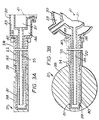
- a further sleeve 38 is shown in Figures 3A and 3B, surrounding and forming part of the arm 22.
- This sleeve 38 is keyed to the heat sink 21 at its outer end, and at its inner end has a ring gear 39 mating with a rotary drive means indicated diagrammatically at 40.
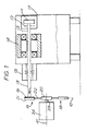
- the purpose of this drive 40 is to produce rotary movement of the heat sink 21 about an axis 10 (shown in Fig 1) of the support arm 22.
- a first movement is a fine adjustment of, for example, plus or minus 7° on either side of a plane perpendicular to the axis of rotation of the wheel 19. This adjustment is provided to allow adjustment of the implant angle by the ion beam 13.
- a second movement provided by the drive means 40 comprises a rotation of the heat sink support base 21 through 90°, to an orientation in which the plane of the heat sink 21 contains the axis of rotation 41 of the rotor 19.
- the purpose of this orientation is for loading and unloading as will be described hereinafter.
- a wide variety of arrangements for rotation of the heat sink 21 can be provided in the hub structure 20, including centrifugally driven arrangements.
- the outer end 31 of the arm 22 may be threaded for only a short portion at the entrance to the heat sink 21, or a thrust race may be provided close to the hub.
- a smooth cylindrical surface which is a close rotational fit with a smooth bore in the block 28. Again the interface may be filled with vacuum grease but this is not essential.
- the wall of the end 31 of the arm 22 is in this case arranged to be a thin wall, between the passage 34, and the block 28, and is arranged to be deformable under the substantial hydrostatic pressure which builds up in the coolant 33 during high speed rotation of the heat sink 21.
- the inner wall 31 expands elastically under the influence of the high hydrostatic pressure, converting the easy sliding and rotation fit which is available when stationary, into intimate contact during high speed rotation.
- the outer end 31 of the arm 22 is not threaded at all, but the support base 21 is secured to the support arm 22 by a thrust race.
- the outer surface of the end 31 of the support arm 22 is a close sliding fit with the plain inner surface of the bore 29 of the support base 21, and all the surfaces are rigid and non-deformable with centrifugal force. Thermal contact is ensured by vacuum grease which is urged into contact with the surfaces by centrifugal force ensuring a void free interface medium. This allows rotation while spinning.
- FIG. 4B twenty-five target wafers 16 are stacked vertically in a cassette 42 mounted in a load lock 43. Means are provided (not shown) for giving a vertical indexing movement of the cassette 42 to bring a selected target wafer 16 into alignment with a horizontally moveable platform 44 positioned inside the vacuum chamber 18, opposite a letter box gate valve 45 positioned between the vacuum chamber 18 and the load lock 43.
- the platform 44 is in the form of a thin flat blade, shown in more detail in Figure 5A and 5B.
- an orientation member 46 consisting of a pedestal having a vertical support shaft 47 and a horizontal portion 48.
- the blade 44 has a left hand portion defining an aperture 49 between parallel sides 50, and a narrower projecting portion 51 defining an aperture 52.
- the pedestal 48 is able to pass through both apertures 49 and 52.
- the blade 44 is moveable between a first position indicated in full lines in Figures 5A and 5B, in which the blade 44 is moved towards the right, and a second position shown in dotted lines in Figure 5A in which the blade 44 is moved toward the left.
- the projecting portion 51 of the blade 44 extends into the cassette 42, and the pedestal 48 is able to move upwardly and downwardly through the aperture 49 between the sides 50.
- each heat sink 21 Extending inwardly from the sides 50 of the blade 44 are 4 wafer support fingers 53. Corresponding notches 54 are provided in each heat sink 21, allowing the heat sinks 21 to be rotated through the aperture 49 without contacting the support fingers 53.
- the operation of loading and unloading cassettes is as follows.
- the blade 44 passes through the letter box gate valve 45 to a position under a target wafer 16 to be loaded.
- the cassette 42 is indexed downwards to leave the target wafer 16 on the projecting portion 51 of the blade 44. At this time the blade is in the first position.
- the blade 44 then moves horizontally back through the letter box gate valve to the second position, and stops with the target wafer 16 over the orientation pedestal 46.
- the pedestal 46 passes upwardly through the aperture 51 and lifts the target wafer 16 off the blade 44.
- the target wafer is then rotated for orientation detection, and then rotated to the required position. While this is happening the blade 44 returns to the first position with the projecting portion 51 extending into the cassette 42.
- the cassette 42 is indexed downwardly to the next position to deposit a further target wafer on the platform 44.
- the pedestal 46 is lowered to deposit the oriented wafer onto the wafer support fingers 53 of the blade 44.
- the blade 44 is then moved back through the gate valve to the second position to the left in Figure 5A.
- the first selected target wafer 16 is now in a loading position in correlation with the rotating heat sinks 21, while the second mentioned target wafer is positioned above the orientation pedestal 47.
- the wheel 19 is indexed slowly in rotation to bring a heat sink 21 upwardly through the aperture 49 to pick a wafer 16 off the blade 44.
- the orientation pedestal 47 lifts a second target wafer from the blade 44, and the cycle is repeated to continue orienting and loading wafers.
- Wafers are unloaded by reversing the steps set out above, except that the orientation step can be omitted.
- Figure 4B a single loading and unloading arrangement is provided, but if required loading and unloading can be effected at two stations, placed at the 3 o'clock and 9 o'clock positions of the wheel 19.
- ion implantation it may be necessary to reorient the wafer between different stages of implanting. It can be done by unloading a wafer onto the blade, and lifting and reorienting the wafer by the pedestal 46, and returning the wafer to the heat sink, without the need to take the wafer back out of the vacuum chamber into the cassette.
- Horizonal loading is preferred because of the use of gravity which simplifies equipment.
- a vertical position of the wafers is preferred for reasons of cleanliness. In previous machines it has been necessary to move the entire scanning wheel to a horizontal position, if horizontal loading is required.
- the present arrangement allows a simple rotation of the heat sink from the vertical to the horizontal position for loading purposes.
- a sheet of aluminium 60 has stamped from it a series of flaps 61, each produced by cutting three sides 62, 63 and 64 of a rectangle.
- the flap 61 then remains attached to the sheet 60 by the fourth side 65 of the rectangle, which forms a hinge between the sheet 60 and the flap 61.
- the flap 61 is pushed outwardly from the sheet, and in a further step, the flap 61 is then bent through an angle of more than 90°, to assume the folded position shown in Figure 6A.
- the final step of bending the flap 61 can be achieved for example by an air blast.
- the aluminum sheet may have a thickness of 0.05mm, and each rectangular flap 61 may be a square of side lmm.
- the spacing of the flaps may be, as shown in Figure 7, equal to the dimensions of the flaps.
- the sheet 60 is shown secured by adhesive or braze 66 to a heat sink 21.
- Figure 6B the same arrangement is shown, but with a target wafer 16 positioned on top of the heat sink 21, and lightly clamped thereto, by clamps not shown.
- the position of the flap 61 is shown in dotted lines, when the sandwich is at rest.
- the wheel 19 is rotated at high speed, the effect of centrifugal force on the flaps 61 bends the flaps to the position shown in full lines in Figure 6B.
- the effect of this is to provide a large multiplicity of substantial contact areas 67 in which the flap 61 is forced into intimate contact with the wafer 16. This produces excellent thermal contact between the wafer 16 and the heat sink 21.
- the orientation of the flaps is chosen so that centrifugal force acting on the flaps tends to lift the flaps.
- the spacing between the wafer and the heat sink, and the thickness of the foil and the rotation speed of the disc are chosen so as not to allow the flaps to overbend.
- over 7000 contacts can be achieved on a 200mm diameter wafer.
- Figures 8A and 8B there is shown an alternative form of device for providing thermal contact between a target element and a heat sink support base embodying the invention.
- Figures 8A and 8B correspond generally to Figures 6A and 6B, and show the device in an unloaded, and loaded, condition respectively.
- the device again consists of a sheet 60 of aluminium foil, but in this embodiment the foil is folded in a concertina arrangement, and is not cut to provide the flaps.
- the sheet 60 provides projections 61 by virtue of the folding of the sheet.
- the sheet 60 is secured at line contacts 70 to the body 66 by braze contact.
- the projections 61 When loaded as shown in Figure 8B, the projections 61 are pressed sideways to form flaps as shown, by the effect of the target wafer 16. After the projections 61 have been deformed as shown in Figure 8B, the projections behave as flaps and operate in the same manner as has been described with reference to 6b, the thermal contact being made at the contact areas 67.
Landscapes
- Physical Vapour Deposition (AREA)
Claims (17)
- Appareil pour la soumission d'éléments cibles à un faisceau ionique en vue d'une implantation d'ions, comprenant; un rotor de support (19) qui comporte plusieurs bases de support (21) pour supporter des éléments cibles (16), lesdites bases de support (21) étant montées sur ledit rotor de support (19) et réparties autour de celui-ci; un moyen de rotation principal (24) pour faire tourner le rotor de support (19) autour d'un axe de rotation principal (41), les éléments cibles (l6) étant situés dans des plans transversaux par rapport à l'axe de rotation (41), à travers un faisceau ionique (13) de manière à produire en service un balayage des éléments cibles (16) par le faisceau ionique (13); et un moyen (40) pour donner à chaque base de support (21) une position angulaire par rapport audit rotor de support (19) dans son ensemble; caractérisé en ce que ledit moyen de positionnement angulaire (40) comprend un moyen de rotation supplémentaire (40) agencé de manière à faire tourner la base de support (21) autour d'un axe transversal qui est essentiellement radial par rapport à l'axe principal (41).
- Appareil selon la revendication 1, dans lequel l'axe transversal (10) de chaque base de support (21) est radial par rapport à l'axe principal (41) de rotation du rotor de support (19).
- Appareil selon la revendication 1 ou 2, dans lequel ledit moyen de rotation supplémentaire (40) pour faire tourner la base de support (21) assure un réglage fin de l'angle de la base de support (21) par rapport à un plan perpendiculaire a l'axe principal (41) de rotation du rotor de support (19), de manière à régler l'angle d'implantation relatif à l'implantation ionique.
- Appareil selon l'une quelconque des revendications 1 à 3, dans lequel ledit moyen de rotation supplémentaire (40) fournit la possibilité de faire tourner la base de support (21) de sorte qu'il se trouve dans un plan contenant l'axe principal (41) de rotation du rotor de support (19) ou approximativement dans un tel plan, en vue du chargement et du déchargement d'éléments cibles (16) sur la base de support (21) et à partir de celle-ci.
- Appareil selon la revendication 4, dans lequel ledit moyen de rotation supplémentaire (40) fournit la possibilité de faire tourner la base de support (21) d'un angle de ± 90° au moins.
- Appareil selon l'une quelconque des revendications 1 à 5, dans lequel le rotor de support (19) comprend une structure de noyau central (20) et plusieurs bras de support (22) qui s'étendent chacun vers l'extérieur à partir de la structure de noyau (20), chaque base de support (21) étant montée à rotation sur un bras de support (22) de manière à tourner autour dudit axe transversal (10) qui est situé essentiellement dans la direction du bras de support (22).
- Appareil selon la revendication 6, dans lequel il est prévu, à la jonction entre chaque base de support (21) et son bras de support (22), un élément déformable de conduction thermique, et la jonction a une forme telle qu'en service, cet élément soit comprimé par la force centrifuge pour constituer un élément de conduction thermique, dépourvu de vides, entre la base et le bras.
- Appareil selon la revendication 7, dans lequel chacune desdites bases de support (21) est montée sur son bras de support (22) par une partie du bras de support (22) qui pénètre dans un trou (29) formé dans la base de support (21) avec, entre la base de support (21) et le bras de support (22), une jonction telle qu'un mouvement aisé de rotation de la base par rapport au bras soit possible à l'arrêt, mais qu'un contact métallique étroit soit produit sous l'effet de la force centrifuge lors de la rotation du rotor en service.
- Appareil selon la revendication 8, dans lequel chaque base de support (21) est montée sur son bras de support (22) par vissage du bras de support dans la base de support (21).
- Appareil selon l'une quelconque des revendications 1 à 9 avec les caractéristiques de la revendication 4, dans lequel l'appareil comprend un mécanisme de chargement et/ou de déchargement pour charger et/ou décharger des éléments cibles (l6) sur les bases de support (21) et à partir de celles-ci, le mécanisme comprenant une plateforme mobile (44) pour supporter un élément cible (16), un moyen qui déplace la plateforme (44) entre une première position, dans laquelle un élément cible (l6) peut être déposé sur la plateforme (44) et/ou en être retiré par un moyen d'alimentation et/ou de réception (42), et une seconde position, dans laquelle un élément cible (l6) peut être soulevé à partir de la plateforme (44) et/ou déposé sur celle-ci par une base de support (21) du rotor (19).
- Appareil selon la revendication 10, dans lequel le mécanisme comprend un organe d'orientation (46) pour supporter un élément cible (16) et pour donner par rotation à l'élément une orientation choisie avant son transfert sur une base de support (21), et dans lequel la plateforme (44) présente une ouverture de transfert à travers laquelle l'organe d'orientation peut être déplacé vers le haut pour retirer de la plateforme (44) un élément cible qui repose sur celle-ci au-dessus de l'ouverture, et à travers laquelle l'organe d'orientation (46) peut se déplacer vers le bas pour déposer un élément cible (16) sur la plateforme (44).
- Appareil selon l'une quelconque des revendications 1 à 11, dans lequel chaque base de support (21) se comporte comme un dissipateur de chaleur et il est prévu une multiplicité de saillies mobiles (61) qui s'étendent à partir de la base de support (21) pour établir un contact thermique avec un élément cible (16) sur la base de support (21), les saillies mobiles (61) étant telles qu'en service, elles puissent se déplacer depuis la base (21) en direction de l'élément (l6), en réponse à la force centrifuge.
- Appareil selon la revendication 12, dans lequel les saillies mobiles (61), qui s'étendent à partir de la base de support (21), comprennent une multiplicité de volets (61) inclinés vers l'extérieur à partir de la base de support (21), de façon a établir un contact thermique avec l'élément cible (16), les volets étant disposés par rapport à l'axe de rotation principal (41) de telle manière qu'au cours de la rotation autour de cet axe (41), la force centrifuge ait pour effet de repousser les volets vers l'extérieur à partir de la base de support (21).
- Appareil selon l'une quelconque des revendications 1 à 13, comportant un moyen (25) pour produire un balayage supplémentaire à faible vitesse d'un élément cible (16) par le faisceau (13), transversalement par rapport audit premier balayage par le faisceau.
- Procédé d'implantation d'ions dans un élément cible en dirigeant un faisceau ionique (13) sur une région cible, comprenant les étapes consistant à disposer plusieurs éléments cibles (16) sur des bases de support (21) montées sur un rotor de support (19) et réparties autour de celui-ci, les éléments cibles étant situés dans des plans transversaux par rapport à un axe principal (41) de rotation du rotor (19); à régler la position angulaire de chaque base de support (21) par rapport au rotor de support (19) dans son ensemble, de manière à effectuer un réglage de l'angle d'implantation relatif à l'implantation d'ions; à faire tourner le rotor de support (19) autour de l'axe principal (41) pour faire passer les éléments cibles (16) à travers la région cible et produire ainsi un balayage rapide des éléments cibles (16) par le faisceau ionique (13); et à produire un balayage lent d'un élément cible (16) par le faisceau (13), transversalement par rapport au balayage rapide, par un mouvement relatif entre le faisceau (13) et la cible (16);
caractérisé en ce que ladite étape de réglage de l'angle d'implantation consiste à faire tourner chaque base de support (21) autour d'un axe transversal (10) qui est essentiellement radial par rapport à l'axe principal (41). - Procédé d'implantation d'ions dans un élément cible en dirigeant un faisceau ionique (13) sur une région cible, comprenant les étapes consistant à disposer plusieurs éléments cibles (16) sur des bases -de support (21) montées sur un rotor de support (19) et réparties autour de celui-ci, les éléments cibles étant situés dans des plans transversaux par rapport à un axe principal (41) de rotation du rotor (19); à faire tourner le rotor de support (19) autour de l'axe principal (41) pour faire passer les éléments cibles (16) à travers la région cible et produire ainsi un balayage rapide des éléments cibles (16) par le faisceau ionique (13); et à produire un balayage lent d'un élément cible (16) par le faisceau (13), transversalement par rapport au balayage rapide, par un mouvement relatif entre le faisceau (13) et la cible (16);
caractérisé en ce que l'étape de mise en place des éléments cibles (l6) sur les bases de support (21) comprend les opérations consistant à charger un élément cible sur une base de support (21) qui se trouve dans un plan contenant l'axe principal (41) du rotor (19), ou approximativement dans un tel plan; et à faire tourner la base de support (21) autour d'un axe transversal (10) qui est essentiellement radial par rapport à l'axe principal (41), jusqu'à ce que la base de support (21) se trouve dans un plan perpendiculaire à l'axe principal (41) ou approximativement dans un tel plan. - Procédé selon la revendication 16 comprenant, après l'implantation d'ions, l'étape supplémentaire consistant à faire tourner la base de support (21) autour de l'axe transversal (10) jusqu'à ce que la base de support (21) se trouve dans un plan contenant l'axe principal (41) du rotor (19), ou approximativement dans un tel plan, et à décharger l'élément cible de la base de support (21).
Applications Claiming Priority (2)
| Application Number | Priority Date | Filing Date | Title |
|---|---|---|---|
| GB898922225A GB8922225D0 (en) | 1989-10-03 | 1989-10-03 | Apparatus and methods relating to ion implantation |
| GB8922225 | 1989-10-03 |
Publications (3)
| Publication Number | Publication Date |
|---|---|
| EP0421728A2 EP0421728A2 (fr) | 1991-04-10 |
| EP0421728A3 EP0421728A3 (en) | 1992-01-08 |
| EP0421728B1 true EP0421728B1 (fr) | 1997-05-14 |
Family
ID=10663956
Family Applications (1)
| Application Number | Title | Priority Date | Filing Date |
|---|---|---|---|
| EP90310771A Expired - Lifetime EP0421728B1 (fr) | 1989-10-03 | 1990-10-02 | Appareil et méthode relatifs à l'implantation ionique et au transfert de chaleur |
Country Status (5)
| Country | Link |
|---|---|
| US (1) | US5124557A (fr) |
| EP (1) | EP0421728B1 (fr) |
| JP (1) | JP3142285B2 (fr) |
| DE (1) | DE69030702T2 (fr) |
| GB (1) | GB8922225D0 (fr) |
Families Citing this family (13)
| Publication number | Priority date | Publication date | Assignee | Title |
|---|---|---|---|---|
| US5486702A (en) * | 1993-09-21 | 1996-01-23 | Genus, Inc. | Scan technique to reduce transient wafer temperatures during ion implantation |
| JP2891255B1 (ja) * | 1998-04-15 | 1999-05-17 | 日本電気株式会社 | イオン注入装置 |
| US6331873B1 (en) * | 1998-12-03 | 2001-12-18 | Massachusetts Institute Of Technology | High-precision blooming control structure formation for an image sensor |
| GB2347784B (en) * | 1999-03-11 | 2004-02-11 | Applied Materials Inc | Scanning wheel for ion implantation process chamber |
| US6414328B1 (en) | 1999-11-05 | 2002-07-02 | Kair Nussupov | Method and apparatus for the conveying and positioning of ion implantation targets |
| ES2282657T3 (es) * | 2002-05-17 | 2007-10-16 | Jason E. Schripsema | Modulo fotovoltaico con disipador de calor ajustable y procedimiento de fabricacion. |
| TWI256697B (en) * | 2004-07-08 | 2006-06-11 | Advanced Ion Beam Technology I | Method for preventing wafer defect for a batch-type ion implanter spinning direction particle |
| DE112007003648T5 (de) * | 2007-09-14 | 2010-08-26 | Advantest Corp. | Verbesserte Grenzfläche zur Temperaturkontrolle |
| JP2010015774A (ja) * | 2008-07-02 | 2010-01-21 | Sumco Corp | イオン注入装置 |
| US20120222620A1 (en) * | 2011-03-01 | 2012-09-06 | Applied Materials, Inc. | Atomic Layer Deposition Carousel with Continuous Rotation and Methods of Use |
| CN109444233A (zh) * | 2018-11-13 | 2019-03-08 | 安徽科宝生物工程有限公司 | 一种电化学工作站转换调节实验台 |
| US10971327B1 (en) * | 2019-12-06 | 2021-04-06 | Applied Materials, Inc. | Cryogenic heat transfer system |
| US12002649B2 (en) * | 2021-12-10 | 2024-06-04 | Applied Materials, Inc. | Spinning disk with electrostatic clamped platens for ion implantation |
Family Cites Families (10)
| Publication number | Priority date | Publication date | Assignee | Title |
|---|---|---|---|---|
| US3858547A (en) * | 1973-12-14 | 1975-01-07 | Nils H Bergfelt | Coating machine having an adjustable rotation system |
| EP0017472A1 (fr) * | 1979-04-06 | 1980-10-15 | Lintott Engineering Limited | Appareillage à vide comportant un dispositif de transfer thermique et procédé de fabrication de composants semi-conducteurs utilisant cet appareillage |
| US4483654A (en) * | 1981-02-13 | 1984-11-20 | Lam Research Corporation | Workpiece transfer mechanism |
| US4578589A (en) * | 1983-08-15 | 1986-03-25 | Applied Materials, Inc. | Apparatus and methods for ion implantation |
| US4733091A (en) * | 1984-09-19 | 1988-03-22 | Applied Materials, Inc. | Systems and methods for ion implantation of semiconductor wafers |
| US4745287A (en) * | 1986-10-23 | 1988-05-17 | Ionex/Hei | Ion implantation with variable implant angle |
| US4831270A (en) * | 1987-05-21 | 1989-05-16 | Ion Implant Services | Ion implantation apparatus |
| NL8701603A (nl) * | 1987-07-08 | 1989-02-01 | Philips & Du Pont Optical | Vacuuminrichting voor het vastzuigen van werkstukken. |
| US4965862A (en) * | 1988-05-18 | 1990-10-23 | Varian Associates, Inc. | Disk scanning apparatus for batch ion implanters |
| JP2717822B2 (ja) * | 1988-11-21 | 1998-02-25 | 住友イートンノバ株式会社 | イオン注入装置 |
-
1989
- 1989-10-03 GB GB898922225A patent/GB8922225D0/en active Pending
-
1990
- 1990-10-02 EP EP90310771A patent/EP0421728B1/fr not_active Expired - Lifetime
- 1990-10-02 DE DE69030702T patent/DE69030702T2/de not_active Expired - Fee Related
- 1990-10-03 JP JP02267517A patent/JP3142285B2/ja not_active Expired - Fee Related
- 1990-10-03 US US07/592,374 patent/US5124557A/en not_active Expired - Lifetime
Also Published As
| Publication number | Publication date |
|---|---|
| DE69030702D1 (de) | 1997-06-19 |
| GB8922225D0 (en) | 1989-11-15 |
| EP0421728A3 (en) | 1992-01-08 |
| US5124557A (en) | 1992-06-23 |
| JPH03126223A (ja) | 1991-05-29 |
| JP3142285B2 (ja) | 2001-03-07 |
| DE69030702T2 (de) | 1998-01-15 |
| EP0421728A2 (fr) | 1991-04-10 |
Similar Documents
| Publication | Publication Date | Title |
|---|---|---|
| EP0421728B1 (fr) | Appareil et méthode relatifs à l'implantation ionique et au transfert de chaleur | |
| US4498833A (en) | Wafer orientation system | |
| US4745287A (en) | Ion implantation with variable implant angle | |
| US4733091A (en) | Systems and methods for ion implantation of semiconductor wafers | |
| US4620738A (en) | Vacuum pick for semiconductor wafers | |
| US4776744A (en) | Systems and methods for wafer handling in semiconductor process equipment | |
| US4899059A (en) | Disk scanning apparatus for batch ion implanters | |
| JP5035345B2 (ja) | イオン注入装置、基板クランプ機構、及びイオン注入方法 | |
| JP2573779B2 (ja) | 半導体ウェハをイオンインプランテーションする装置 | |
| US5947675A (en) | Cassette transfer mechanism | |
| US6270307B1 (en) | Method for aligning wafers in a cassette | |
| US4672210A (en) | Ion implanter target chamber | |
| US4965862A (en) | Disk scanning apparatus for batch ion implanters | |
| US6530157B1 (en) | Precise positioning device for workpieces | |
| KR20070080125A (ko) | 반도체 제조용 웨이퍼 이송로봇 및 그를 구비한 반도체제조설비 | |
| US6114705A (en) | System for correcting eccentricity and rotational error of a workpiece | |
| JPS6254089A (ja) | ウエハ自公転機構 | |
| EP0342933B1 (fr) | Appareil de balayage de disque-support pour implanteurs ioniques par fournées | |
| US20020124964A1 (en) | Wafer support plate assembly having recessed upper pad and vacuum processing apparatus comprising the same | |
| EP0228901A2 (fr) | Appareil de transfert de pastilles | |
| EP0508748A2 (fr) | Système de centrage pour plaquette | |
| JPH07249394A (ja) | イオン注入方法及び装置 | |
| JP3382885B2 (ja) | イオン注入装置及びイオン注入方法 | |
| JPH01173558A (ja) | イオン注入装置 | |
| JPH06334026A (ja) | オリエンテーションフラット合わせ機内蔵型ウエハ収納装置 |
Legal Events
| Date | Code | Title | Description |
|---|---|---|---|
| PUAI | Public reference made under article 153(3) epc to a published international application that has entered the european phase |
Free format text: ORIGINAL CODE: 0009012 |
|
| AK | Designated contracting states |
Kind code of ref document: A2 Designated state(s): CH DE FR GB IT LI NL |
|
| PUAL | Search report despatched |
Free format text: ORIGINAL CODE: 0009013 |
|
| AK | Designated contracting states |
Kind code of ref document: A3 Designated state(s): CH DE FR GB IT LI NL |
|
| 17P | Request for examination filed |
Effective date: 19920629 |
|
| 17Q | First examination report despatched |
Effective date: 19921023 |
|
| GRAG | Despatch of communication of intention to grant |
Free format text: ORIGINAL CODE: EPIDOS AGRA |
|
| GRAH | Despatch of communication of intention to grant a patent |
Free format text: ORIGINAL CODE: EPIDOS IGRA |
|
| GRAH | Despatch of communication of intention to grant a patent |
Free format text: ORIGINAL CODE: EPIDOS IGRA |
|
| GRAA | (expected) grant |
Free format text: ORIGINAL CODE: 0009210 |
|
| AK | Designated contracting states |
Kind code of ref document: B1 Designated state(s): CH DE FR GB IT LI NL |
|
| PG25 | Lapsed in a contracting state [announced via postgrant information from national office to epo] |
Ref country code: IT Free format text: LAPSE BECAUSE OF FAILURE TO SUBMIT A TRANSLATION OF THE DESCRIPTION OR TO PAY THE FEE WITHIN THE PRE;WARNING: LAPSES OF ITALIAN PATENTS WITH EFFECTIVE DATE BEFORE 2007 MAY HAVE OCCURRED AT ANY TIME BEFORE 2007. THE CORRECT EFFECTIVE DATE MAY BE DIFFERENT FROM THE ONE RECORDED.SCRIBED TIME-LIMIT Effective date: 19970514 Ref country code: NL Free format text: LAPSE BECAUSE OF FAILURE TO SUBMIT A TRANSLATION OF THE DESCRIPTION OR TO PAY THE FEE WITHIN THE PRESCRIBED TIME-LIMIT Effective date: 19970514 Ref country code: CH Effective date: 19970514 Ref country code: LI Effective date: 19970514 |
|
| REG | Reference to a national code |
Ref country code: CH Ref legal event code: EP |
|
| REF | Corresponds to: |
Ref document number: 69030702 Country of ref document: DE Date of ref document: 19970619 |
|
| ET | Fr: translation filed | ||
| NLV1 | Nl: lapsed or annulled due to failure to fulfill the requirements of art. 29p and 29m of the patents act | ||
| REG | Reference to a national code |
Ref country code: CH Ref legal event code: PL |
|
| PLBE | No opposition filed within time limit |
Free format text: ORIGINAL CODE: 0009261 |
|
| STAA | Information on the status of an ep patent application or granted ep patent |
Free format text: STATUS: NO OPPOSITION FILED WITHIN TIME LIMIT |
|
| 26N | No opposition filed | ||
| REG | Reference to a national code |
Ref country code: GB Ref legal event code: IF02 |
|
| PGFP | Annual fee paid to national office [announced via postgrant information from national office to epo] |
Ref country code: DE Payment date: 20051025 Year of fee payment: 16 |
|
| PGFP | Annual fee paid to national office [announced via postgrant information from national office to epo] |
Ref country code: FR Payment date: 20051028 Year of fee payment: 16 |
|
| PGFP | Annual fee paid to national office [announced via postgrant information from national office to epo] |
Ref country code: GB Payment date: 20060908 Year of fee payment: 17 |
|
| PG25 | Lapsed in a contracting state [announced via postgrant information from national office to epo] |
Ref country code: DE Free format text: LAPSE BECAUSE OF NON-PAYMENT OF DUE FEES Effective date: 20070501 |
|
| REG | Reference to a national code |
Ref country code: FR Ref legal event code: ST Effective date: 20070629 |
|
| PG25 | Lapsed in a contracting state [announced via postgrant information from national office to epo] |
Ref country code: FR Free format text: LAPSE BECAUSE OF NON-PAYMENT OF DUE FEES Effective date: 20061031 |
|
| GBPC | Gb: european patent ceased through non-payment of renewal fee |
Effective date: 20071002 |
|
| PG25 | Lapsed in a contracting state [announced via postgrant information from national office to epo] |
Ref country code: GB Free format text: LAPSE BECAUSE OF NON-PAYMENT OF DUE FEES Effective date: 20071002 |