EP0421847B1 - Befestigungsvorrichtung für Computerperipherien - Google Patents
Befestigungsvorrichtung für Computerperipherien Download PDFInfo
- Publication number
- EP0421847B1 EP0421847B1 EP90402673A EP90402673A EP0421847B1 EP 0421847 B1 EP0421847 B1 EP 0421847B1 EP 90402673 A EP90402673 A EP 90402673A EP 90402673 A EP90402673 A EP 90402673A EP 0421847 B1 EP0421847 B1 EP 0421847B1
- Authority
- EP
- European Patent Office
- Prior art keywords
- peripheral
- fastening
- fastening device
- lugs
- support part
- Prior art date
- Legal status (The legal status is an assumption and is not a legal conclusion. Google has not performed a legal analysis and makes no representation as to the accuracy of the status listed.)
- Expired - Lifetime
Links
Images


Classifications
-
- G—PHYSICS
- G11—INFORMATION STORAGE
- G11B—INFORMATION STORAGE BASED ON RELATIVE MOVEMENT BETWEEN RECORD CARRIER AND TRANSDUCER
- G11B33/00—Constructional parts, details or accessories not provided for in the other groups of this subclass
- G11B33/12—Disposition of constructional parts in the apparatus, e.g. of power supply, of modules
- G11B33/121—Disposition of constructional parts in the apparatus, e.g. of power supply, of modules the apparatus comprising a single recording/reproducing device
- G11B33/123—Mounting arrangements of constructional parts onto a chassis
- G11B33/124—Mounting arrangements of constructional parts onto a chassis of the single recording/reproducing device, e.g. disk drive, onto a chassis
-
- G—PHYSICS
- G06—COMPUTING OR CALCULATING; COUNTING
- G06F—ELECTRIC DIGITAL DATA PROCESSING
- G06F1/00—Details not covered by groups G06F3/00 - G06F13/00 and G06F21/00
- G06F1/16—Constructional details or arrangements
- G06F1/18—Packaging or power distribution
- G06F1/183—Internal mounting support structures, e.g. for supporting printed circuit boards
- G06F1/184—Mounting of motherboards
-
- G—PHYSICS
- G06—COMPUTING OR CALCULATING; COUNTING
- G06F—ELECTRIC DIGITAL DATA PROCESSING
- G06F1/00—Details not covered by groups G06F3/00 - G06F13/00 and G06F21/00
- G06F1/16—Constructional details or arrangements
- G06F1/18—Packaging or power distribution
- G06F1/183—Internal mounting support structures, e.g. for supporting printed circuit boards
- G06F1/187—Mounting of fixed or removable disk drives
-
- H—ELECTRICITY
- H05—ELECTRIC TECHNIQUES NOT OTHERWISE PROVIDED FOR
- H05K—PRINTED CIRCUITS; CASINGS OR CONSTRUCTIONAL DETAILS OF ELECTRIC APPARATUS; MANUFACTURE OF ASSEMBLAGES OF ELECTRICAL COMPONENTS
- H05K7/00—Constructional details common to different types of electric apparatus
- H05K7/14—Mounting supporting structure in casing or on frame or rack
- H05K7/1422—Printed circuit boards receptacles, e.g. stacked structures, electronic circuit modules or box like frames
- H05K7/1427—Housings
- H05K7/1429—Housings for circuits carrying a CPU and adapted to receive expansion cards
Definitions
- the present invention relates to a device for fixing computer peripherals.
- the first object of the invention is, therefore, to allow rapid and automated assembly of a peripheral constituting the basic configuration of a microcomputer, such as a floppy disk drive.
- the fixing device for a computer peripheral comprising a support part (1), removably mounted integral with a chassis (90, 91, 92) of a microcomputer, the part support comprising a first (10) a second (12) and a third surface (11), the so-called second and third surfaces (12,11) being on the one hand mutually parallel and on the other hand perpendicular to the first surface (10) thus forming a U-shaped part with legs oriented downwards, said first surface (10) comprising first fixing means for fixing a first device (3) to said support piece on a side of said first surface (10) opposite the legs extending downward, and in which a first set of lugs (103) is disposed on said first surface (10) and an elastic blade (7) is disposed perpendicular to said first surface (10) and parallel to said first set of lugs (103), said blade being fixed to one of said second (12) and third (11) surfaces perpendicular to the first surface (10), said elastic blade (7) having a second set of lug
- the elastic blade (7) is removably attached to the second surface (12), the second surface being perpendicular to, and integrated into said first surface (10) and arranged in a direction opposite to the first set of lugs (103), the blade (7) having two cutouts (710A, 710B) and two openings (7110, 7130) said second surface having two tongues (121A, 121B) and two bosses (125A, 125B) formed by stamping and deformation of said second surface (12), the cutouts (710A, 710B) being adapted to be placed under the two languages (121A, 121B) of the second surface (12), the bosses (125A, 125B) being arranged to be clipped into the corresponding openings (7110, 7130) of the elastic blade.
- An additional aim is to allow a rapid and automated assembly of the peripherals making it possible to constitute the basic configuration of a microcomputer in particular on a support which allows the mounting of at least two peripherals of which the second can be an ultra fast unwinder magnetic tape in cartridge (streamer) or floppy drive unit or hard drive.
- said support piece (1) is adapted to receive a second means for removably mounting a second device (4) said second fixing means being mounted between the legs of the support piece (1) in U shape.
- An additional aim is to allow the mounting of fragile peripherals.
- the second fixing means for mounting a second peripheral (4) comprises a pair of stamped cutouts (102A, 102B, 110A, 110B) disposed in each of the second (12) and third (11) surfaces, each of the cutouts comprising a vertical cutout portion and an inclined ramp portion extending laterally, said inclined ramp portion ending with a locking point (1201) for accommodating grommets (41A, 41B, 41C, 41D) of elastic material and shock absorber mounted on fixing screws (40A, 40B, 40C, 40D) aimed at the fixing holes (42A, 42B, 42C, 42D) of a housing of the second peripheral (4).
- a further object of the invention is to allow the mounting of a peripheral box in the format for example of 31 ⁇ 2 inches, less than the format constituted by the distance separating the legs from the support piece and corresponding substantially to the format 51 ⁇ 4 inches.
- the second fixing means for fixing a second peripheral (4) comprise by a U-shaped bracket (50, 51, 52) having a surface (50) which is arranged horizontally when said second means of fasteners are mounted on the support piece (1) and having two legs oriented vertically upwards, said bracket being removably mounted using a hinge assembly (520, 123) and suspended from the first surface (10 ) by an elastic tongue (510, 511) adjacent to the first leg comprising a hooking tongue (512) intended, after having passed through an opening (104) in the first surface (10), to press against the upper face of the first surface (10), the first leg (51) of the U coming to bear against the underside of said first surface (10) near the latching tongue (512).
- the hinge joint (123, 520) is integrated into the second leg (52) of the U, and includes means for positioning the horizontal surface. (50) of the stirrup once the tongue (512) is locked, the means being constituted by a folded rim (521) pressing on the upper part of a cutout (122) provided for this purpose in the second surface (12), while the tongues (520A, 520B) forming the articulation press on the lower part of the cutouts (123A, 123B) provided in the second surface (12).
- An additional object of the invention is to allow the mounting of an additional peripheral, such as a hard disk, not requiring access from outside the housing of the microcomputer during operation, but allowing, when the housing is open, easy access to elements placed below this device on the main electronic card of the machine.
- an additional peripheral such as a hard disk
- the device comprises third means for mounting a third device and said device comprising an opening (102) provided in the first surface (10), behind the first means for the first device (3 ), the opening (102) being intended to receive said third means (8) for fixing the device (2) mounted in a direction perpendicular to the direction of the first device (3), said third means (8) making it possible to tilt temporarily the peripheral to access a connector (60) located on a printed circuit board (6) on which is mounted the support piece (1).
- An additional aim is to allow the mounting of three peripherals.
- the third fixing means (8) comprises a U-shaped stirrup (80, 81, 82) having two lateral legs (81, 82) and a central portion (80), the legs (81, 82) of which are extended front and back of the central part of the U by arms (812, 811, 821, 822), and arranged opposite a first pair of arms (812, 822) means (1020A, 1020B) allowing the hinge on the sides of the opening (102), a second pair of arms (811, 821) comprising means (8211, 8111) for latching onto the surfaces (1020C, 1020D) of the opening provided for this purpose to constitute the position of use of the peripheral (2), while the elasticity of this second pair of arms (811, 821) allows them to be released by disengaging to allow tilting.
- a final object of the invention is to propose a use of the device for fixing computer peripherals.
- the fixing device is mounted in a computer chassis having a bottom panel, a front plate (90) and a rear plate (91) by sliding between grooves formed by bosses (900, 910) produced on the front (90) and rear (91) plates of the chassis and secured to the plates and to a printed circuit board (6) resting on the bottom (92) of the computer chassis by removable fixing means (111, 110, 124).
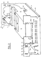
- the fixing device according to the invention makes it possible to mount on a support piece (1), a first computer peripheral consisting of a floppy drive (3), accessible by the front face (90) , Figure 2, the chassis of a machine consisting of a microcomputer in which the device for fixing peripherals is mounted.
- This floppy drive (3) is the basic configuration of the machine.
- This peripheral attachment device also allows optional mounting of a hard disk drive (2), in a direction perpendicular to the direction of the floppy drive, and at the rear thereof to allow optimal use of the space available at the rear of the floppy drive (3).
- this hard disk drive (2) is mounted on a cradle (8) pivoting around the joint (1020B, 1020A), so as to allow access to electronic equipment, constituted for example by connectors (60), arranged on the printed circuit board (6, FIG. 6) on which the support piece (1) is fixed, using a screw and a tab (124) comprising a nut.
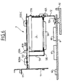
- the support part (1) As shown in FIG. 3, the connector (60) faces the opening (102) made in the upper surface (10) of the support piece (1).
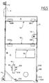
- the support part (1) as shown in FIGS. 4 and 5, comprises a first surface (10) provided with an opening (102) intended to receive the fixing means (8) of the hard disk (2), and an opening (100) intended to allow the passage of the plies of wires connecting, by the connectors (31, 32), FIGS. 1 and 3, the floppy disk drive (3) to the electronic circuit appearing on the card (6).
- the support part (1) also has a second surface (12) perpendicular to the first surface and oriented downwards so as to form, with a third surface (11), a part whose section is substantially U-shaped.
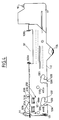
- the second and third surfaces, respectively (12, 11), of the support piece (1) comprise on each surface, (12) respectively (11), a pair of cutouts (120A, 120B), respectively (110A, 110B, figure 1), each consisting of a vertical cutout (1202), extending laterally by an inclined ramp (1203) to finish with a fixing point constituted by a boss (1201).
- the vertical cutout (1202) also includes on one of its sides a boss (1200) making it possible to constitute a hard point avoiding too easy passage from the inclined part to the vertical part.
- the inclined portion (1203) is inclined downward at an angle less than 90 ° relative to the vertical part.
- Each of the threaded holes receives the corresponding thread (40A, 40B, 40C, 40D) with a screw, the head of which, for example with a hexagon socket, allows attachment to the body of the housing (4).
- This screw shown in an enlarged manner in the bubble of FIG. 1, comprises in addition to its threading (400) a shoulder (401) constituting, with the head (402), a groove (403) in which is housed a grommet washer (41).
- Each screw (40A, 40B, 40C, 40D) is associated with a grommet washer (41A, 41B, 41C, 41D) made of elastic material.
- the grommet washer (41) comprises a disc (411) separated from a second disc (410) by a groove corresponding to the thickness of the second and third lateral surfaces (12 or 11) of the support part (1).
- the two discs (411, 410) are interconnected by a central junction part (412).
- the assembly constituted by each grommet washer, each screw and each cutout (120) forms a suspension and fixing element for the peripheral casing with a damping means constituted by the grommet washer made of elastic material.
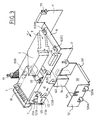
- FIG. 3 represents a variant in which, in place of a peripheral of dimension corresponding to the module of 5 1 ⁇ 4 inches, a peripheral of smaller dimension is mounted, corresponding to the standards of peripheral known as 3 1 ⁇ 2 inches between the lateral surfaces (12 , 11) of the fixing part (1).
- a second means of fixing (50, 51, 52) of the peripheral is used, constituted by a stirrup comprising a central part (50), lateral legs (52, 51) substantially forming a part whose cross section is U-shaped.
- the horizontal part (50) is extended forward and backward by a tongue (501) folded down in a perpendicular plane, so as to constitute a reinforcement of rigidity of this surface.
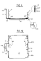
- this surface (50) includes bosses (500, FIG. 12) making it possible to press on this boss, as shown in FIG. 6, the peripheral (5) and to maintain this peripheral by screws which pass through the holes provided on these bosses (500) for screwing into the other threaded part of the housing (5).
- the housing assembly (5) fixing means (50, 51, 52) is pivotally mounted by hooking the tabs (520A, 520B), Figures 3 and 12, in the cutouts (123A, 123B) provided on the second surface (12, Figure 4).
- the surface (52) is brought into contact with the surface (12), which allows the tongue (521), represented in FIG. 11, to penetrate into the cutout (122) of the surface (12, FIGS. 3, 4 and 11), to come into abutment against the upper part of this cutout (122), while the tongues (520) are in abutment on the lower parts of the cutouts (123).
- the tongue (510) extending the horizontal surface (50) comprises a portion (511) perpendicular to this tongue (510), and ends in a horizontal part (512) provided with a boss (5120), comes by elastic deformation to pass this horizontal part (512) through a cutout (104) provided on the first surface (10) and so as to position the boss (5120) opposite the cutout (105) to thus constitute a brake on the withdrawal of the tongue (512).
- the length of the part (511) and legs (51) constituting the U-shaped section stirrup, constituted by the surfaces (51, 50, 52), is calculated so that when the tongue (512) is supported on the upper face of the first surface (10), the end of the legs (51) of the suspension U of the peripheral housing (5) is supported on the underside of the surface (10), as shown in FIG. 6.
- Each lug consists of a stud (1030) cut from the surface (10), as shown in dotted lines in FIG. 5, and folded back perpendicular to this surface, as shown in FIGS. 4 and 6.
- This stud (1030) comprises, at a distance corresponding to the location of the peripheral fixing holes and oriented along the axis of symmetry of the second peripheral, that is to say perpendicular to the axis of symmetry of the first peripheral, a lug (1031).
- This elastic blade (7) comprises an inclined part (1070) which gives it its elasticity and a flat part (71) which allows it to be fixed to the lateral surface (12).
- This fixing is carried out by means of the tongues (121A, 121B), cut out from the surface (12), as shown in FIGS. 4 and 5.
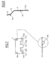
- cutouts (710A, 710B) include, as shown in Figure 8, a slight draft (710) facilitating the introduction into the tongues.
- the cutouts (710A, 710B) materialize in the elastic blade three legs (711, 712, 713) whose two outer legs (711, 713) are respectively provided with an opening (7110, 7130) which allows to receive bosses ( 125A, 125B) formed on the surface (12) to prevent upward movement of the elastic blade (7) once it has been placed on the surface (12).
- the support piece (1) thus provided with the elastic blade (7), allows the installation of a floppy disk drive (3), by first introducing the fixing holes in the lugs (1031A, 1031B) of the piece support (1), and then pivoting the housing, while spreading the elastic blade, then let the lugs of the elastic blade return to lodge in the fixing holes located on the face of the housing opposite .
- the hard drive (2) is fixed by a stirrup (8), with a main U-shaped section, as shown in FIGS. 9 and 10.
- the lateral legs (81, 82) of this stirrup extend in front and in rear by side arms (811, 812, 821, 822).
- Each of the arms is extended outwards by a tongue (8120, 8111, 8211, 8220) in a direction perpendicular to the legs (81, 82) and parallel to the horizontal plane (80) on which the device is fixed.
- the horizontal plane (80) has a series of four holes (800) for fixing the device on the connecting piece.
- the front and rear arms (811, 812, 821, 822) form a slight angle with the extensions of the side surfaces (81, 82).
- This slight angle makes it possible to give travel to the elastic arm of the fixing device.
- This clearance allows the introduction of the tabs (8120, 8220) in the respective holes (1020A, 1020B), Figures 4 and 3.
- the holes (1020A, 1020B, 1020C, 1020D) are made in cutouts of the surface (10) , after having folded a part of it so as to have the axis of symmetry of the traces (1020A, 1020B) parallel to the surfaces (10, 11, 12) to form a reinforcement of the surface (10).
- the support piece (1) corresponding holes (1020C, 1020D) in which the tongues (8111, 8211 ) can penetrate after deformation of the elastic arms (811, 821).
- the device (2) is assembled first by fixing it to the connecting piece (8).
- the rear arms (812, 822) are then introduced so that the tongues (8120, 8220) penetrate into the orifices (1020A, 1020B), slightly deforming these arms inwards.
- the tilting of the housing gradually brings the front tongues (8111, 8211) opposite the orifices (1020C) and (1020D), deforming the arms (811, 821) inwards. After releasing the arms (811, 821), the tongues penetrate into the orifices and secure the assembly. To access the connector (60), it will suffice, by pressing on the arms (811, 821), to release the tabs from the corresponding holes, and thus allow the device to tilt.
- the support part (1) equipped with one or more peripherals according to the desired configuration, and corresponding in a variant of maximum configuration to the equipment shown in FIG. 1, or in another variant of maximum configuration with the equipment shown in Figure 3, is then introduced into the machine chassis consisting of a front plate (90, Figure 2), a rear plate (91) made integral with a bottom plate (92), on which rests a printed circuit board (6).
- the support piece (1) is slid so that its lateral side (11) is guided and held by bosses (900) made on the front plate (90) of the chassis and bosses (910) made on the plate rear (91) of the chassis. These bosses (900, 910) are arranged on either side of the location in which the lateral surface (11) is to be maintained.
- a front nut secured by a tongue (125) to the surface (12) makes it possible to link this surface (12) to the front face (90) by a screw (1250) shown in FIG. 2.
- the tab (124) makes it possible to fix a screw intended to make the surface (12) of the printed circuit ( 6) and the underside of the chassis (92), as shown in FIG. 6.
- peripheral fixing device which makes it possible to equip a machine, at the customer's request, with different options in a simple and economical manner. peripheral point of view.
- simplicity of mounting the various peripherals allows automation and easy access to the main parts of the machine for maintenance operations.
Landscapes
- Engineering & Computer Science (AREA)
- Theoretical Computer Science (AREA)
- General Physics & Mathematics (AREA)
- Human Computer Interaction (AREA)
- Physics & Mathematics (AREA)
- General Engineering & Computer Science (AREA)
- Power Engineering (AREA)
- Computer Hardware Design (AREA)
- Microelectronics & Electronic Packaging (AREA)
- Casings For Electric Apparatus (AREA)
- Mounting Of Printed Circuit Boards And The Like (AREA)
- Mounting Components In General For Electric Apparatus (AREA)
- Connection Of Plates (AREA)
Claims (9)
- Befestigungseinrichtung für Computer-Peripheriegerät, mit einem Trageteil (1), das an einem Rahmen (90, 91, 92) eines Mikrocomputers auf abnehmbare Weise fest angebracht ist, wobei das Trageteil eine erste (10), eine zweite (12) und eine dritte Fläche (11) aufweist, wobei die zweite und die dritte Fläche (12, 11) einerseits zueinander parallel und andererseits zur ersten Fläche (10) senkrecht sind und somit ein U-Teil mit nach unten gerichteten Schenkeln bilden, wobei die erste Fläche (10) erste Befestigungsmittel aufweist, um ein erstes Peripheriegerät (3) am Trageteil an einer Seite der genannten ersten Fläche (10) zu befestigen, welche den nach unten sich erstreckenden Schenkeln entgegengesetzt ist, wobei in der Befestigungseinrichtung an der ersten Fläche (10) eine erste Gruppe von Vorsprüngen (103) angeordnet ist und senkrecht zur ersten Fläche (10) und parallel zur ersten Gruppe von Vorsprüngen (103) ein elastisches Plättchen (7) angeordnet ist, wobei das Plättchen entweder an der zweiten (12) oder an der dritten (11) Fläche befestigt ist, die zur ersten Fläche (10) senkrecht sind, wobei das elastische Plättchen (7) eine zweite Gruppe von Vorsprüngen (73) besitzt, die in diesem Plättchen gebildet sind, wobei die zweite Gruppe von Vorsprüngen (73) von der ersten Gruppe von Vorsprüngen (103) um eine Strecke entfernt ist, die dem Zwischenraum von Befestigungslöchern des Gehäuses des ersten Peripheriegeräts (3) entsprechen, und wobei in der Befestigungseinrichtung jeder Vorsprung der zweiten Gruppe in eine entsprechende Befestigungsöffnung eindringt, wenn das genannte Peripheriegerät an der Einrichtung angebracht wird.
- Befestigungseinrichtung gemäß Anspruch 1, dadurch gekennzeichnet, daß das elastische Plättchen (7) auf ablösbare Weise an der zweiten Fläche (12) befestigt ist, wobei die zweite Fläche zur ersten Fläche (10) senkrecht und mit dieser einteilig ausgebildet und in einer Richtung angeordnet ist, die zur ersten Gruppe von Vorsprüngen (103) entgegengesetzt ist, wobei das Plättchen (7) zwei Ausschnitte (710A, 710B) und zwei Öffnungen (7110, 7130) besitzt, wobei die zweite Fläche zwei Laschen (121A, 121B) und zwei Höcker (125A, 125B) besitzt, die durch einen Ziehvorgang und durch Verformen der zweiten Fläche (12) gebildet sind, wobei die Ausschnitte (710A, 710B) so beschaffen sind, daß sie unter den beiden Zungen (121A, 121B) der zweiten Fläche (12) angeordnet werden, wobei die Höcker (125A, 125B) so angeordnet sind, daß sie in die entsprechenden Öffnungen (7110, 7130) des elastischen Plättchens einrasten.
- Befestigungseinrichtung gemäß Anspruch 1, dadurch gekennzeichnet, daß das Trageteil (1) so beschaffen ist, daß es ein zweites Mittel für die lösbare Anbringung eines zweiten Peripheriegeräts (4) aufnehmen kann, wobei das zweite Befestigungsmittel zwischen den Schenkeln des U-förmigen Trageteils (1) angebracht ist.
- Befestigungseinrichtung gemäß Anspruch 3, dadurch gekennzeichnet, daß das zweite Befestigungsmittel für die Anbringung eines zweiten Peripheriegeräts (4) ein Paar von gezogenen Ausschnitten (102A, 102B, 110A, 110B) umfaßt, die in der zweiten (12) und in der dritten (11) Fläche angeordnet sind, wobei jeder Ausschnitt einen vertikalen Ausschnittbereich und einen seitlich sich erstreckenden, schrägen Rampenbereich aufweist, wobei der schräge Rampenbereich in einem Verriegelungspunkt (1201) endet, um Drahtdurchführungen (41A, 41B, 41C, 41D) aus elastischem und dämpfenden Material aufzunehmen, die an Befestigungsschrauben (40A, 40B, 40C, 40D) angebracht sind, die in die Befestigungsbohrungen (42A, 42B, 42C, 42D) eines Gehäuses des zweiten Peripheriegerätes (4) eingeschraubt sind.
- Befestigungseinrichtung gemäß Anspruch 3, dadurch gekennzeichnet, daß die zweiten Befestigungsmittel für die Befestigung eines zweiten Peripheriegerätes (4) einen U-Bügel (50, 51, 52) aufweisen, der eine Fläche (50), die horizontal angeordnet ist, wenn die zweiten Befestigungsmittel am Trageteil (1) angebracht sind, sowie zwei vertikal nach oben gerichtete Schenkel besitzt, wobei der Bügel auf ablösbare Weise mit Hilfe einer Scharnierverbindung (520, 123) angebracht ist und an der ersten Fläche (10) mittels einer elastischen Lasche (510, 511) aufgehängt ist, die an den ersten Schenkel angrenzt und eine Einhaklasche (512) aufweist, die dazu bestimmt ist, sich nach dem Durchführen durch eine Öffnung (104) der ersten Fläche (10) gegen die obere Fläche der ersten Fläche (10) abzustützen, wobei sich der erste Schenkel (51) des U's an der unteren Fläche der ersten Fläche (10) in der Nähe der Einhaklasche (512) abstützt.
- Befestigungseinrichtung gemäß Anspruch 5, dadurch gekennzeichnet, daß das Scharniergelenk (123, 520) mit dem zweiten Schenkel (52) des U's einteilig ausgebildet ist und Mittel aufweist, um die horizontale Fläche (50) des Bügels zu positionieren, sobald die Zunge (512) verriegelt ist, wobei die Mittel durch eine umgeknickte Kante (521) gebildet sind, die sich am oberen Teil eines Ausschnitts (122) abstützen, der hierzu in der zweiten Fläche (12) vorgesehen ist, während die Laschen (520A, 520B), die das Gelenk bilden, sich am unteren Teil der Ausschnitte (123A, 123B) abstützen, die in der zweiten Fläche (12) vorgesehen sind.
- Befestigungseinrichtung gemäß einem der Ansprüche 1 bis 6, dadurch gekennzeichnet, daß die Einrichtung dritte Mittel aufweist, um ein drittes Peripheriegerät anzubringen, und die Einrichtung eine Öffnung (102) aufweist, die in der ersten Fläche (10) hinter den ersten Mitteln für das erste Peripheriegerät (3) vorgesehen ist, wobei die Öffnung (102) dazu bestimmt ist, die dritten Mittel (8) für die Befestigung des Peripheriegeräts (2), die in einer zur Richtung des ersten Peripherigeräts (3) senkrechten Richtung angebracht sind, aufzunehmen, wobei die dritten Mittel (8) ein vorübergehendes Kippen des Peripheriegeräts gestatten, um auf einen Verbindungsanschluß (60) zuzugreifen, der sich auf einer gedruckten Schaltungskarte (6) befindet, auf der das Trageteil (1) angebracht ist.
- Befestigungseinrichtung gemäß Anspruch 7, dadurch gekennzeichnet, daß das dritte Befestigungsmittel (8) einen U-Bügel (80, 81, 82) aufweist, der zwei Seitenschenkel (81, 82) und einen Mittelbereich (80) besitzt, wobei die Schenkel (81, 82) über den mittleren Teil des U's nach vorne und nach hinten durch Arme (812, 811, 821, 822) verlängert sind, wobei gegenüber einem ersten Paar von Armen (812, 822) Mittel (1020A, 1020B) angeordnet sind, die eine Anlenkung an den Seiten der Öffnung (102) gestatten, wobei ein zweites Paar von Armen (811, 821) Mittel (8211, 8111) zum Einrasten an den Flächen (1020C, 1020D) der hierzu vorgesehenen Öffnung aufweist, um die Betriebsposition des Peripherigerätes (2) zu bilden, während die Elastizität dieses zweiten Paars von Armen (811, 821) deren Ablösung durch Ausrasten gestattet, um das Kippen zuzulassen.
- Anwendung der Befestigungseinrichtung für Computer-Peripheriegerät gemäß einem der vorangehenden Ansprüche, dadurch gekennzeichnet, daß eine Befestigungseinrichtung in einem Computerrahmen mit einer Bodenplatte, einer vorderen Platte (90) und einer hinteren Platte (91) durch Gleiten zwischen Rillen angebracht wird, die durch Höcker (900, 910) gebildet sind, die in der vorderen Platte (90) und in der hinteren Platte (91) des Rahmens verwirklicht sind, und mit den Platten sowie mit einer auf dem Boden (92) des Rahmens aufruhenden gedruckten Schaltungskarte (6) durch abnehmbare Befestigungsmittel (111, 110, 124) verbunden ist.
Applications Claiming Priority (2)
| Application Number | Priority Date | Filing Date | Title |
|---|---|---|---|
| FR8913034 | 1989-10-05 | ||
| FR8913034A FR2652940B1 (fr) | 1989-10-05 | 1989-10-05 | Dispositif de fixation de peripheriques d'ordinateur. |
Publications (2)
| Publication Number | Publication Date |
|---|---|
| EP0421847A1 EP0421847A1 (de) | 1991-04-10 |
| EP0421847B1 true EP0421847B1 (de) | 1994-03-30 |
Family
ID=9386115
Family Applications (1)
| Application Number | Title | Priority Date | Filing Date |
|---|---|---|---|
| EP90402673A Expired - Lifetime EP0421847B1 (de) | 1989-10-05 | 1990-09-27 | Befestigungsvorrichtung für Computerperipherien |
Country Status (6)
| Country | Link |
|---|---|
| US (1) | US5136466A (de) |
| EP (1) | EP0421847B1 (de) |
| JP (1) | JPH0728145B2 (de) |
| DE (1) | DE69007732T2 (de) |
| ES (1) | ES2054298T3 (de) |
| FR (1) | FR2652940B1 (de) |
Families Citing this family (49)
| Publication number | Priority date | Publication date | Assignee | Title |
|---|---|---|---|---|
| DE10126331C2 (de) * | 2001-05-30 | 2003-04-24 | Fujitsu Siemens Computers Gmbh | Steckkarte |
| JPH03134718A (ja) * | 1989-10-20 | 1991-06-07 | Toshiba Corp | 携帯型電子機器 |
| CA2071381C (en) * | 1991-07-19 | 1998-12-15 | Youji Satou | Electronic apparatus, card-type electronic component used with the electronic apparatus, and electronic system with expanding apparatus for expanding function of electronic apparatus |
| US5404271A (en) | 1991-07-30 | 1995-04-04 | Kabushiki Kaisha Toshiba | Electronic apparatus having a card storing section formed within a body between a support frame and an upper case of the body and having functional elements mounted between the support frame and a lower case of the body |
| US5214567A (en) * | 1991-12-19 | 1993-05-25 | Intel Corporation | Modular peripheral platform having two disk drives and one electrical connector |
| US5524104A (en) * | 1992-03-30 | 1996-06-04 | Sony Corporation | Compact disk drive arrangement with one disk mounted on top of another |
| FR2694154B1 (fr) * | 1992-07-24 | 1994-09-16 | Vibrachoc Sa | Support pour boîtier d'équipement électrique d'aéronef. |
| US5306079A (en) * | 1992-10-08 | 1994-04-26 | Enlight Corporation | Multi-purpose frame for a computer |
| DE9214324U1 (de) * | 1992-10-22 | 1992-12-17 | Siemens AG, 8000 München | Unterputzinstallationssystem |
| US5260851A (en) * | 1992-10-23 | 1993-11-09 | Chiou Ming D | Housing for a computer power supply unit with hard disk drive storage chamber thereon |
| US5566383A (en) * | 1993-04-01 | 1996-10-15 | Zenith Data Systems Corporation | Drive platform assembly with rotatable mounting brackets and automatic grounding bracket |
| FR2704350B1 (fr) * | 1993-04-22 | 1995-06-02 | Bull Sa | Structure physique d'un sous système de mémoire de masse. |
| US5503472A (en) * | 1993-06-29 | 1996-04-02 | Sun Microsystems, Inc. | Method and apparatus for assembly of a multi-disk pack unit |
| US5715139A (en) * | 1993-09-09 | 1998-02-03 | Kabushiki Kaisha Toshiba | Portable electronic apparatus having a frame supporting functional components, and method of assembling the portable electronic apparatus |
| US5587879A (en) * | 1994-01-28 | 1996-12-24 | Sun Microsystems, Inc. | Mounting arrangement for computer hardware components and method |
| US6215074B1 (en) | 1994-04-29 | 2001-04-10 | International Business Machines Corporation | Direct mounting system for a disk drive |
| US5543609A (en) * | 1994-10-28 | 1996-08-06 | Symbol Technologies, Inc. | Arrangement for and method of providing shock protection and vibration isolation for a scan module |
| US5748404A (en) * | 1995-09-18 | 1998-05-05 | Alps Electric Co., Ltd. | Magnetic recording/reproducing device with chassis support structure |
| US5748442A (en) * | 1995-11-08 | 1998-05-05 | Palo Alto Design Group | Personal computer and chassis having interchangeable trim plates for horizontal model and tower model configuration, one trim plate having a larger periphery for use as a base plate |
| KR0125586Y1 (ko) * | 1995-11-16 | 1998-09-15 | 김광호 | 일체형 개인용 컴퓨터의 드라이브 킷 착탈구조 |
| US5680293A (en) * | 1996-09-13 | 1997-10-21 | Dell U.S.A., L.P. | Screwless hard drive mounting in a computer system with a chassis via a first bracket rigidly mounted to the chassis and a second bracket movably mounted to the chassis |
| EP0934591B1 (de) * | 1996-10-22 | 2002-04-03 | Océ Printing Systems GmbH | Baugruppe für ein aufbausystem |
| US5768099A (en) * | 1997-01-23 | 1998-06-16 | Dell Computer Corporation | Computer with an improved disk drive mounting assembly |
| KR100252249B1 (ko) | 1997-08-28 | 2000-04-15 | 윤종용 | 컴퓨터 시스템 |
| US5980003A (en) * | 1998-01-31 | 1999-11-09 | First International Computer, Inc. | Detachable case assembly for computer |
| TW444894U (en) * | 1998-08-31 | 2001-07-01 | Hon Hai Prec Ind Co Ltd | Computer components rotation hanging rack |
| US6040980A (en) * | 1998-10-21 | 2000-03-21 | Micron Electronics, Inc. | Disk drive to chassis mounting apparatus and method |
| AU1622900A (en) | 1998-11-13 | 2000-06-05 | Greystone Peripherals, Inc. | Method and apparatus for aligning device interconnections |
| US6301124B1 (en) | 1999-02-04 | 2001-10-09 | Dell Usa, L.P. | Computer chassis identification method |
| TW433526U (en) * | 1999-04-06 | 2001-05-01 | Hon Hai Prec Ind Co Ltd | Fixing and holding apparatus for data access device |
| US6262888B1 (en) * | 1999-06-30 | 2001-07-17 | Dell Usa, L.P. | Impact damping system for peripheral device |
| US6236563B1 (en) * | 1999-06-30 | 2001-05-22 | Dell Usa, L.P. | Retention apparatus for a peripheral device |
| US6359775B1 (en) | 1999-08-11 | 2002-03-19 | Micron Technology, Inc. | Accessible desktop computer |
| US6719385B1 (en) * | 2000-01-14 | 2004-04-13 | International Business Machines Corporation | System for holding a device in a computer system |
| TW535971U (en) * | 2000-05-30 | 2003-06-01 | Hon Hai Prec Ind Co Ltd | Fixture for data accessing device |
| US6507487B1 (en) * | 2000-11-08 | 2003-01-14 | International Business Machines Corporation | Removable structures for mounting computer drive devices, pivotable between operating and service positions |
| US9879448B2 (en) * | 2001-12-14 | 2018-01-30 | Perkins Technical Services, Inc. | Knob clamp lock |
| US6639796B2 (en) | 2002-01-24 | 2003-10-28 | Agilent Technologies, Inc. | Fastenerless clip for quick installation and removal of system components in a computer system |
| US6717803B2 (en) | 2002-02-12 | 2004-04-06 | Agilent Technologies, Inc. | Bracket for quick installation and removal of system components in a computer system |
| TW562221U (en) * | 2002-12-27 | 2003-11-11 | Hon Hai Prec Ind Co Ltd | Mounting device for disk drive |
| US7038915B2 (en) * | 2003-08-05 | 2006-05-02 | International Business Machines Corporation | Apparatus, system, and method for arraying electrical devices in a cabinet |
| US7088579B1 (en) | 2003-11-13 | 2006-08-08 | Storage Technology Corporation | Small form factor disk drive carrier |
| TWI265768B (en) * | 2005-04-12 | 2006-11-01 | Asustek Comp Inc | Hard disk drive holding device |
| JP4286859B2 (ja) * | 2006-12-08 | 2009-07-01 | パナソニック株式会社 | 携帯端末 |
| US8213174B1 (en) | 2010-01-08 | 2012-07-03 | Juniper Networks, Inc. | Vibration-damping mount |
| TWM398320U (en) * | 2010-09-06 | 2011-02-11 | Lite On Technology Corp | Frame module which used in fixing electronic device |
| TWI489930B (zh) * | 2012-08-28 | 2015-06-21 | 緯創資通股份有限公司 | 限位機構及其相關電子裝置 |
| JP6547598B2 (ja) | 2015-11-10 | 2019-07-24 | 富士通株式会社 | 情報処理装置 |
| CN113414563B (zh) * | 2021-07-16 | 2022-07-05 | 重庆航天职业技术学院 | 一种计算机cpu的拆卸设备 |
Family Cites Families (13)
| Publication number | Priority date | Publication date | Assignee | Title |
|---|---|---|---|---|
| GB472046A (en) * | 1936-03-11 | 1937-09-13 | Philco Radio & Television Corp | Improvements in the manufacture and construction of radio receivers |
| US2584173A (en) * | 1947-12-02 | 1952-02-05 | Jess Van Fowler | Tiltable panel assembly |
| US4076165A (en) * | 1976-06-03 | 1978-02-28 | Motorola, Inc. | Mounting arrangement for chassis and printed circuit board with method of assembly |
| US4135337A (en) * | 1977-09-12 | 1979-01-23 | Medlin Lewis B | Mounting means for electric outlet box |
| JPS556118A (en) * | 1978-06-26 | 1980-01-17 | Sharp Corp | Control panel for microwave oven |
| US4268100A (en) * | 1979-01-05 | 1981-05-19 | International Business Machines Corporation | Pivotally mounted printed circuit board holder |
| US4599485A (en) * | 1984-12-21 | 1986-07-08 | Smolik Robert A | Electrical receptacle box assembly |
| US4754397A (en) * | 1985-02-15 | 1988-06-28 | Tandem Computers Incorporated | Fault tolerant modular subsystems for computers |
| DE3523830A1 (de) * | 1985-07-03 | 1987-01-29 | Siemens Ag | Vorrichtung zum netzanschluss einer auf einer leiterplatte angeordneten stromversorgungs-baugruppe |
| FR2614372B1 (fr) * | 1987-04-22 | 1989-06-09 | Vibrachoc Sa | Dispositif de verrouillage d'un boitier d'equipements electroniques sur un plateau |
| US4725244A (en) * | 1987-07-02 | 1988-02-16 | Tektronix, Inc. | System for assembling an electronic work station |
| US4937806A (en) * | 1988-02-12 | 1990-06-26 | Mdb Systems, Inc. | Shock-isolated portable mass data storage device |
| US4964017A (en) * | 1989-04-26 | 1990-10-16 | Intelligent Instrumentation, Inc. | Adaptable housing for embedding of computer-controlled products |
-
1989
- 1989-10-05 FR FR8913034A patent/FR2652940B1/fr not_active Expired - Fee Related
-
1990
- 1990-09-27 EP EP90402673A patent/EP0421847B1/de not_active Expired - Lifetime
- 1990-09-27 ES ES90402673T patent/ES2054298T3/es not_active Expired - Lifetime
- 1990-09-27 DE DE69007732T patent/DE69007732T2/de not_active Expired - Fee Related
- 1990-10-04 JP JP2267509A patent/JPH0728145B2/ja not_active Expired - Fee Related
- 1990-10-05 US US07/592,474 patent/US5136466A/en not_active Expired - Lifetime
Also Published As
| Publication number | Publication date |
|---|---|
| DE69007732T2 (de) | 1994-08-11 |
| JPH03165095A (ja) | 1991-07-17 |
| FR2652940B1 (fr) | 1994-03-11 |
| FR2652940A1 (fr) | 1991-04-12 |
| ES2054298T3 (es) | 1994-08-01 |
| DE69007732D1 (de) | 1994-05-05 |
| US5136466A (en) | 1992-08-04 |
| EP0421847A1 (de) | 1991-04-10 |
| JPH0728145B2 (ja) | 1995-03-29 |
Similar Documents
| Publication | Publication Date | Title |
|---|---|---|
| EP0421847A1 (de) | Befestigungsvorrichtung für Computerperipherien | |
| US20040079711A1 (en) | System and method for rack cable management | |
| EP0542594B1 (de) | Modulare elektronische Einheit | |
| FR3000718A1 (fr) | Dispositif de pliage pour dispositif de porte-bicyclettes | |
| EP3788852B1 (de) | Verfahren zum verriegeln/entriegeln eines abnehmbaren moduls und anordnung zur implementierung | |
| EP0144258A1 (de) | Bildschirmkonsole | |
| EP3758175A1 (de) | Schaltschrank mit klimaanlagenblock | |
| EP1073324B1 (de) | Elektromagnetische Abschirmvorrichtung für eine Schublade | |
| EP1238327B1 (de) | Anzeigevorrichtung und rahmen für eine solche | |
| EP1717883A1 (de) | Sockel und Klemme enthaltende Befestigungseinrichtung für Batterie | |
| FR3029702A1 (fr) | Connecteur coaxial integre a un blindage et carte electronique equipee d'un tel connecteur | |
| EP0989649B1 (de) | Trägervorrichtung für elektrische Geräte | |
| TWI272051B (en) | Employment of an over-bent ledge of a rack component to support an over-bent ledge of a drop-in chassis | |
| EP3409996B1 (de) | Adapter zur befestigung eines elektronischen zahlungsterminals auf einer halterung | |
| EP0192519B1 (de) | Vorrichtung zur Montage einer Trägerplatte in einem Verteilerschrank | |
| WO2026008535A1 (fr) | Ensemble comportant un socle d'accueil et un dispositif d'affichage | |
| EP3800692B1 (de) | Befestigungsteil eines wechselrahmens für gabelstaplerbatterien | |
| EP0421846B1 (de) | Mehrzweckbefestigungsteil | |
| FR3094422A1 (fr) | Module de fixation pour enceinte | |
| EP0642752A1 (de) | Schreibunterlage, ausgebildet als Stütze für eine Schublade in welche unter anderem eine Komputertastatur untergebracht werden kann | |
| FR3056373A1 (fr) | Equipement pour maintenir un composant a l'interieur d'un boitier d'ordinateur | |
| EP0665439B1 (de) | Adapter für Testanordnung für elektronische Geräte | |
| EP3473017A1 (de) | Tonwiedergabe oder -verarbeitungsvorrichtung mit austauschbarer verkleidung | |
| NL1027404C2 (nl) | Bevestigingsinrichting voor Wiel van Rolstoel. | |
| EP4610104A1 (de) | System zur lösbaren befestigung eines bildschirms an einem armaturenbrett eines flugzeugs und anzeigesystem mit solch einem befestigungssystem |
Legal Events
| Date | Code | Title | Description |
|---|---|---|---|
| PUAI | Public reference made under article 153(3) epc to a published international application that has entered the european phase |
Free format text: ORIGINAL CODE: 0009012 |
|
| AK | Designated contracting states |
Kind code of ref document: A1 Designated state(s): DE ES FR GB IT |
|
| 17P | Request for examination filed |
Effective date: 19910521 |
|
| 17Q | First examination report despatched |
Effective date: 19921218 |
|
| RAP3 | Party data changed (applicant data changed or rights of an application transferred) |
Owner name: BULL S.A. |
|
| GRAA | (expected) grant |
Free format text: ORIGINAL CODE: 0009210 |
|
| AK | Designated contracting states |
Kind code of ref document: B1 Designated state(s): DE ES FR GB IT |
|
| REF | Corresponds to: |
Ref document number: 69007732 Country of ref document: DE Date of ref document: 19940505 |
|
| ITF | It: translation for a ep patent filed | ||
| GBT | Gb: translation of ep patent filed (gb section 77(6)(a)/1977) |
Effective date: 19940607 |
|
| REG | Reference to a national code |
Ref country code: ES Ref legal event code: FG2A Ref document number: 2054298 Country of ref document: ES Kind code of ref document: T3 |
|
| PLBE | No opposition filed within time limit |
Free format text: ORIGINAL CODE: 0009261 |
|
| STAA | Information on the status of an ep patent application or granted ep patent |
Free format text: STATUS: NO OPPOSITION FILED WITHIN TIME LIMIT |
|
| 26N | No opposition filed | ||
| REG | Reference to a national code |
Ref country code: GB Ref legal event code: IF02 |
|
| PGFP | Annual fee paid to national office [announced via postgrant information from national office to epo] |
Ref country code: ES Payment date: 20050920 Year of fee payment: 16 |
|
| PGFP | Annual fee paid to national office [announced via postgrant information from national office to epo] |
Ref country code: GB Payment date: 20060905 Year of fee payment: 17 |
|
| PGFP | Annual fee paid to national office [announced via postgrant information from national office to epo] |
Ref country code: DE Payment date: 20060908 Year of fee payment: 17 |
|
| REG | Reference to a national code |
Ref country code: ES Ref legal event code: FD2A Effective date: 20060928 |
|
| PG25 | Lapsed in a contracting state [announced via postgrant information from national office to epo] |
Ref country code: ES Free format text: LAPSE BECAUSE OF NON-PAYMENT OF DUE FEES Effective date: 20060928 |
|
| PGFP | Annual fee paid to national office [announced via postgrant information from national office to epo] |
Ref country code: IT Payment date: 20070918 Year of fee payment: 18 |
|
| GBPC | Gb: european patent ceased through non-payment of renewal fee |
Effective date: 20070927 |
|
| PG25 | Lapsed in a contracting state [announced via postgrant information from national office to epo] |
Ref country code: DE Free format text: LAPSE BECAUSE OF NON-PAYMENT OF DUE FEES Effective date: 20080401 |
|
| REG | Reference to a national code |
Ref country code: FR Ref legal event code: ST Effective date: 20080531 |
|
| PG25 | Lapsed in a contracting state [announced via postgrant information from national office to epo] |
Ref country code: FR Free format text: LAPSE BECAUSE OF NON-PAYMENT OF DUE FEES Effective date: 20071001 |
|
| PGFP | Annual fee paid to national office [announced via postgrant information from national office to epo] |
Ref country code: FR Payment date: 20060928 Year of fee payment: 17 |
|
| PG25 | Lapsed in a contracting state [announced via postgrant information from national office to epo] |
Ref country code: GB Free format text: LAPSE BECAUSE OF NON-PAYMENT OF DUE FEES Effective date: 20070927 |
|
| PG25 | Lapsed in a contracting state [announced via postgrant information from national office to epo] |
Ref country code: IT Free format text: LAPSE BECAUSE OF NON-PAYMENT OF DUE FEES Effective date: 20080927 |