EP0422464A2 - Wärmeübertragung für ein leichtgängiges Scharniergelenk - Google Patents
Wärmeübertragung für ein leichtgängiges Scharniergelenk Download PDFInfo
- Publication number
- EP0422464A2 EP0422464A2 EP90118688A EP90118688A EP0422464A2 EP 0422464 A2 EP0422464 A2 EP 0422464A2 EP 90118688 A EP90118688 A EP 90118688A EP 90118688 A EP90118688 A EP 90118688A EP 0422464 A2 EP0422464 A2 EP 0422464A2
- Authority
- EP
- European Patent Office
- Prior art keywords
- rotor
- pivot axis
- flat surface
- finger
- thermally conductive
- Prior art date
- Legal status (The legal status is an assumption and is not a legal conclusion. Google has not performed a legal analysis and makes no representation as to the accuracy of the status listed.)
- Granted
Links
- 238000012546 transfer Methods 0.000 title claims abstract description 26
- 230000008878 coupling Effects 0.000 claims abstract description 15
- 238000010168 coupling process Methods 0.000 claims abstract description 15
- 238000005859 coupling reaction Methods 0.000 claims abstract description 15
- 239000010432 diamond Substances 0.000 claims description 23
- 229910003460 diamond Inorganic materials 0.000 claims description 20
- UONOETXJSWQNOL-UHFFFAOYSA-N tungsten carbide Chemical compound [W+]#[C-] UONOETXJSWQNOL-UHFFFAOYSA-N 0.000 claims description 8
- 230000036316 preload Effects 0.000 claims description 6
- 239000007787 solid Substances 0.000 claims description 5
- 238000003780 insertion Methods 0.000 claims description 3
- 230000037431 insertion Effects 0.000 claims description 3
- RYGMFSIKBFXOCR-UHFFFAOYSA-N Copper Chemical compound [Cu] RYGMFSIKBFXOCR-UHFFFAOYSA-N 0.000 description 7
- 229910052782 aluminium Inorganic materials 0.000 description 7
- XAGFODPZIPBFFR-UHFFFAOYSA-N aluminium Chemical compound [Al] XAGFODPZIPBFFR-UHFFFAOYSA-N 0.000 description 7
- 238000000576 coating method Methods 0.000 description 7
- 229910052802 copper Inorganic materials 0.000 description 7
- 239000010949 copper Substances 0.000 description 7
- 239000000463 material Substances 0.000 description 6
- 229910000679 solder Inorganic materials 0.000 description 6
- 238000005476 soldering Methods 0.000 description 6
- 239000013078 crystal Substances 0.000 description 5
- 239000011248 coating agent Substances 0.000 description 4
- 230000000712 assembly Effects 0.000 description 3
- 238000000429 assembly Methods 0.000 description 3
- 239000004809 Teflon Substances 0.000 description 2
- 229920006362 Teflon® Polymers 0.000 description 2
- 229910045601 alloy Inorganic materials 0.000 description 2
- 239000000956 alloy Substances 0.000 description 2
- 238000005219 brazing Methods 0.000 description 2
- 239000002131 composite material Substances 0.000 description 2
- 238000002844 melting Methods 0.000 description 2
- 230000008018 melting Effects 0.000 description 2
- 238000000034 method Methods 0.000 description 2
- 238000012986 modification Methods 0.000 description 2
- 230000004048 modification Effects 0.000 description 2
- 235000013175 Crataegus laevigata Nutrition 0.000 description 1
- BQCADISMDOOEFD-UHFFFAOYSA-N Silver Chemical compound [Ag] BQCADISMDOOEFD-UHFFFAOYSA-N 0.000 description 1
- ATJFFYVFTNAWJD-UHFFFAOYSA-N Tin Chemical compound [Sn] ATJFFYVFTNAWJD-UHFFFAOYSA-N 0.000 description 1
- HCHKCACWOHOZIP-UHFFFAOYSA-N Zinc Chemical compound [Zn] HCHKCACWOHOZIP-UHFFFAOYSA-N 0.000 description 1
- 238000001816 cooling Methods 0.000 description 1
- 230000003247 decreasing effect Effects 0.000 description 1
- 230000001419 dependent effect Effects 0.000 description 1
- 238000013461 design Methods 0.000 description 1
- 230000004907 flux Effects 0.000 description 1
- 239000002783 friction material Substances 0.000 description 1
- 229910052738 indium Inorganic materials 0.000 description 1
- APFVFJFRJDLVQX-UHFFFAOYSA-N indium atom Chemical compound [In] APFVFJFRJDLVQX-UHFFFAOYSA-N 0.000 description 1
- 238000004519 manufacturing process Methods 0.000 description 1
- TWNQGVIAIRXVLR-UHFFFAOYSA-N oxo(oxoalumanyloxy)alumane Chemical compound O=[Al]O[Al]=O TWNQGVIAIRXVLR-UHFFFAOYSA-N 0.000 description 1
- 238000005498 polishing Methods 0.000 description 1
- 239000000843 powder Substances 0.000 description 1
- 229910052709 silver Inorganic materials 0.000 description 1
- 239000004332 silver Substances 0.000 description 1
- 238000012360 testing method Methods 0.000 description 1
- 229910052725 zinc Inorganic materials 0.000 description 1
- 239000011701 zinc Substances 0.000 description 1
Images




Classifications
-
- F—MECHANICAL ENGINEERING; LIGHTING; HEATING; WEAPONS; BLASTING
- F16—ENGINEERING ELEMENTS AND UNITS; GENERAL MEASURES FOR PRODUCING AND MAINTAINING EFFECTIVE FUNCTIONING OF MACHINES OR INSTALLATIONS; THERMAL INSULATION IN GENERAL
- F16C—SHAFTS; FLEXIBLE SHAFTS; ELEMENTS OR CRANKSHAFT MECHANISMS; ROTARY BODIES OTHER THAN GEARING ELEMENTS; BEARINGS
- F16C11/00—Pivots; Pivotal connections
- F16C11/04—Pivotal connections
-
- B—PERFORMING OPERATIONS; TRANSPORTING
- B64—AIRCRAFT; AVIATION; COSMONAUTICS
- B64G—COSMONAUTICS; VEHICLES OR EQUIPMENT THEREFOR
- B64G99/00—Subject matter not provided for in other groups of this subclass
-
- F—MECHANICAL ENGINEERING; LIGHTING; HEATING; WEAPONS; BLASTING
- F16—ENGINEERING ELEMENTS AND UNITS; GENERAL MEASURES FOR PRODUCING AND MAINTAINING EFFECTIVE FUNCTIONING OF MACHINES OR INSTALLATIONS; THERMAL INSULATION IN GENERAL
- F16C—SHAFTS; FLEXIBLE SHAFTS; ELEMENTS OR CRANKSHAFT MECHANISMS; ROTARY BODIES OTHER THAN GEARING ELEMENTS; BEARINGS
- F16C11/00—Pivots; Pivotal connections
- F16C11/04—Pivotal connections
- F16C11/10—Arrangements for locking
- F16C11/103—Arrangements for locking frictionally clamped
-
- F—MECHANICAL ENGINEERING; LIGHTING; HEATING; WEAPONS; BLASTING
- F16—ENGINEERING ELEMENTS AND UNITS; GENERAL MEASURES FOR PRODUCING AND MAINTAINING EFFECTIVE FUNCTIONING OF MACHINES OR INSTALLATIONS; THERMAL INSULATION IN GENERAL
- F16C—SHAFTS; FLEXIBLE SHAFTS; ELEMENTS OR CRANKSHAFT MECHANISMS; ROTARY BODIES OTHER THAN GEARING ELEMENTS; BEARINGS
- F16C2326/00—Articles relating to transporting
- F16C2326/47—Cosmonautic vehicles, i.e. bearings adapted for use in outer-space
-
- Y—GENERAL TAGGING OF NEW TECHNOLOGICAL DEVELOPMENTS; GENERAL TAGGING OF CROSS-SECTIONAL TECHNOLOGIES SPANNING OVER SEVERAL SECTIONS OF THE IPC; TECHNICAL SUBJECTS COVERED BY FORMER USPC CROSS-REFERENCE ART COLLECTIONS [XRACs] AND DIGESTS
- Y10—TECHNICAL SUBJECTS COVERED BY FORMER USPC
- Y10S—TECHNICAL SUBJECTS COVERED BY FORMER USPC CROSS-REFERENCE ART COLLECTIONS [XRACs] AND DIGESTS
- Y10S165/00—Heat exchange
- Y10S165/135—Movable heat exchanger
Definitions
- This invention relates to the field of mechanical hinges or rotary couplings and more particularly to the field of mechanical hinges suitable for use in aerospace, military and industrial applications requiring high thermal conductance, good reliability, low torque, small size, light weight, and a very low thermal gradient across a hinged joint operating in a deep space, vacuum environment.
- Hinged joints typically move heat from a reference member to a pivoted member through a hinge by conducting heat from or to a fixed or reference hinge surface to or from a hinged moving surface.
- the reference member hinge surface is typically an internal sleeve or cylindrical surface.
- the reference or fixed member hinge surface is typically an internal sleeve or cylinder surface, e.g. a gimbal or trunion.
- the moving hinged surface is typically a pin or cylindrical surface that is received by the sleeve or cylindrical reference surface.
- Other forms of hinges use ball bearings.
- the thermal gradient for a given heat load across the joint is a function of the available surface areas, the thermal area contact force, the thermal conductivity of the materials, the temperature at which the joint operates and the atmospheric pressure that the joint is required to operate in.
- Low torque applications typically provide a moving interface between the rotating surfaces. As the interface pressure is decreased, to reduce the torque required to rotate the hinge, the thermal gradient across the joint is increased for a given heat load at a given atmospheric pressure.
- This invention characterizes an improved hinge for reliably coupling heat from a reference or fixed member to a hinged member with a low rotational torque input requirement and a very low thermal gradient for a given heat load.
- the main embodiment employs diamond materials at the hinge interfaces to provide high thermal conductivity (i.e., greater than that for high purity copper) and low friction coefficients (i.e., on the order of teflon).
- the diamond materials may take the form of single crystal industrial diamonds, polycrystalline diamonds or micron layer diamond coatings. For the best performance, all of these configurations must be coupled with other hinge materials of high thermal conductivity (e.g., copper, aluminum, etc.).
- Heat is coupled to the joint and removed from the joint by structural and support elements and by heat pipes where more efficient transfer of heat from one assembly to another is required.
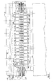
- FIGURE 1. is a top view and FIGURE 2 is a side view of the invention heat transfer hinge 10 having a first rotor 12, and a second rotor 14.
- the configuration shown is for a polycrystalline diamond interface but would follow along the same lines for the single crystal or micron layer diamond interfaces.
- the assemblies within phantom blocks 16 and 18, shown in FIGURE 2 represent a pivot means for pivotally coupling the first rotor to the second rotor. Each rotor is free to pivot on a pivot axis 20 passing between the first and second rotor, 12, 14.
- An arrangement of interleaved finger members such as first rotor fingers 24a, 24b, ..., 24k and second rotor fingers 26a, 26b, ..., 26j located between phantom blocks 16 and 18, couples the first rotor to the second rotor via thermally conductive flat surfaces on adjacent rotor fingers.
- First rotor fingers 24a, 24b, ..., 24k represent a means for thermally coupling a thermally conductive flat surface to the first rotor.
- FIGURE 6 is a schematic exploded view of the arrangement of interleaved fingers shown in FIGURE 2.
- FIGURE 6 is an exploded partial schematic view of sections of FIGURE 2, that shows that each first rotor finger has left and right thermally conductive flat surfaces 28la, 28ra, 28lb, 28rb,..., 28lk, 28rk formed on parallel opposing sides of a respective first rotor finger head 30a, 30b,..., 30k.
- Each first rotor finger head is separated from a corresponding first rotor finger foot 32a, 32b,..., 32k by a first rotor finger fin 34a, 34b,..., 34k.
- FIGURE 6 also shows that second rotor fingers 26a, 26b, ..., 26j represent a means for thermally coupling a thermally conductive flat surface to the second rotor.
- Each second rotor finger has left and right thermally conductive flat surface 36la, 36ra, 36lb, 36rb,..., 36lj, 36rj formed on parallel opposing sides of a respective second rotor finger head 38a, 38b,..., 38j.
- Each second rotor finger head is separated from the respective second rotor finger foot 40a, 40b,...,40j by a second rotor finger fin 42a, 42b,...,42j.
- FIGURE 2 and also FIGUREs 7 and 8, show that the left and right thermally conductive flat surfaces on the first and second rotor fingers are positioned to be normal to the pivot axis by the pivot assemblies within phantom blocks 16 and 18.
- the pivot axis 20 passes centrally through each of the respective thermally conductive flat surfaces. Pivotal support is only provided by the pivot assemblies within phantom blocks 16 and 18.
- Right and left springs 43a, 43b represent a means for holding the first rotor flat surface against the second rotor flat surface as the first rotor 12 is pivoted on the pivot axis 20 with respect to the second rotor 14.
- the alignment of all fingers and the preloading of all first rotor thermally conductive faces against second rotor thermally conductive faces is achieved by jigging the respective first and second rotor fingers into the interleaved alignment apparent in FIGURE 2 before they are rigidly fixed to the respective first and second rotors.
- the jig (not shown) is fashioned to position the thermally conductive surface on each first and second rotor finger to be normal to the pivot axis 20 prior to permanently affixing the finger members to the respective first and second rotors.
- the jig is also designed to allow the pivot axis to pass centrally, or as close to the center of the thermally conductive face of each of the respective thermally conductive flat surfaces as practical.
- each first rotor finger foot 32a, 32b ..., 32k is coupled to the first rotor by positioning each first rotor finger foot in a corresponding first rotor foot aperture 44a, 44b ... 44k.
- Each first rotor foot aperture is shaped to freely receive a corresponding first rotor finger foot without interference to avoid disturbing the jigged alignment of the first rotor fingers.
- Each second rotor finger foot 40a, 40b ..., 40k is coupled to the second rotor by positioning each second rotor finger foot in a corresponding second rotor foot aperture.
- Each second rotor foot aperture is shaped to freely receive a corresponding second rotor finger foot without interference to avoid disturbing the jigged alignment of the second rotor fingers.
- the first and second rotor apertures shown in FIGURE 2 are shaped as rectangular notches.
- the first rotor apertures 44a, 44b, ..., 44k are formed in the lower edge of the first rotor 12.
- the second rotor apertures 46a, 46b, ... 46j are in the upper edge of the second rotor 14.
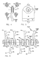
- FIGUREs 4 and 5 provide a detail side view and a detailed front view of a rotor finger.
- the finger is formed from a core of copper or aluminum.
- a left tungsten carbide disk 48 is received in a left mounting hole.
- a right tungsten carbide disk 50 is received in a right mounting hole.
- the left and right disks are attached by means of solder preforms positioned in the respective left and right mounting holes under the respective disks before raising the temperature of the jigged finger assembly to the melting point of the solder preform.
- the external surface of the disks are precoated with polycrystalline diamond material or with an alternative low friction material having good thermal conductivity. Single crystal diamond elements and micron layer diamond are believed to be suitable alternative coating elements.
- FIGUREs 4 and 5 also show that the thermally conductive faces, such as face 52a and 52b are typically circular in shape.
- the coating is applied to the tungsten carbide disks prior to affixing the disks to a finger member.
- Each disk has flat parallel surfaces.
- the polycrystalline surface of the inserts are flat to a tolerance of one tenthousandth of an inch and have a two micro inch finish.
- the right and left faces 52a, 52b, as shown in FIGURE 4 are machined and polished to be parallel to within one thousandth of an inch.
- the disks are coated with the polycrystalline diamond coating by companies such as Megadiamond, at 275 West 2230 North, Provo, Utah, 84604.
- Other sources for the diamond interface material include Sumitomo Electric USA Inc., at 23440 Hawthorne Blvd., Bldg. 2, Rm 210, Torrance, CA, 90505-4762 for single crystal diamonds and the Beam Alloy Corp., 6360 Dublin Industrial Lane, Dublin, Ohio 43017 for micron layer diamond coatings.
- the polycrystalline surface provides a hard wear resistant surface equal to that of diamond with compressive stress allowables of 500,000 psi.
- the surface is commonly formed by assembling fine diamond powder and tungsten carbide into a refractory mold. The assembly is then subjected to pressures that are near one million psi and heated by electric current to about 3000 degrees Fahrenheit. Upon cooling, the diamond crystals sinter together to form a solid mass with a tungsten carbide backing.
- the thermal conductivity of the polycrystalline coating is greater than that of pure copper and the coefficient of friction is less than that of Teflon (0.04). These properties combine to achieve the most efficient heat transfer possible between rotating surfaces. Heat transfer increases with increasing contact pressure across the joint or by increasing the area of the joint formed by the rotating thermally conductive faces while holding the contact pressure constant.
- the tungsten carbide side of the disk is affixed to opposing sides of the head of each respective first and second rotor finger by soldering or brazing.
- the disks are attached to the finger heads using indium solder.
- a solder preform is used between the back of each disk and the corresponding surface of the finger.
- the disks are held in contact with opposing sides of a finger by a finger assembly jig (not shown) to insure parallel surfaces as the jigged finger and disk arrangement is raised in temperature above the melting point of the solder.
- the opposing left and right polycrystalline diamond surfaces are controlled to be parallel to within one thousandth of an inch by specification to insure low torque operation when the fingers are interposed between adjacent fingers and also to insure good thermal contact with adjacent thermally conductive flat surfaces.
- Fluxless soldering can be used for copper, aluminum and silver.
- One method of fluxless soldering consists of an ultrasonic generator and soldering head with a transducer coupling for the solder tip and heater. Brazing which takes place at temperatures above 800 degrees F. can be used with both copper and aluminum and their alloys.
- FIGUREs 7 and 8 provide expanded views of the pivot means 16, 18 or hinges on which the first and second rotors 12, 14 rotate in greater detail.
- the right pivot means within phantom box 16 is depicted in FIGURE 7 as a yoke having a left tang 60 and a right tang 62 coupled to the first rotor 12 to form a slot 64.
- a center tang 66 is coupled to the second rotor 14 for insertion into the slot 64.
- a right pin 68 is supported by the left and right tang 60, 62 in coaxial alignment with the pivot axis 20.
- the right pin 68 passes through the center tang 66 to provide a bearing surface on which to pivot the second rotor 14.
- the second rotor 14 is pivotally supported by the right pin 68.
- Belville spring washers 43a represent a right spring means for providing a constant preload force to the pin with respect to the first rotor 12.
- the pin extends freely through the yoke and applies a preload force to thermally conductive flat surface 28ra to hold a first first rotor flat surface, such as flat surface 28la against a second rotor flat surface, such as surface 36ra.
- Retaining plate 72 is coupled to the first rotor 12 by screw 74 as it passes through retaining plate 72 into a threaded receiving hole 76.
- the retaining plate is normal to the pivot axis 20.
- the pin has a collar 78 to support the right spring washers 43a as the partially compressed right springs 43a apply a force to the left against the collar with respect to the retaining plate 72.
- the springs are coaxially positioned on the pin 68.
- the left pivot means within phantom box 18 is depicted in FIGURE 8 as a yoke having a left tang 82 and a right tang 84 coupled to the first rotor 12 to form a slot 86.
- a center tang 90 is coupled to the second rotor 14 for insertion into the slot 86.
- a left pin 92 is supported by the left and right tang 82, 84 in coaxial alignment with the pivot axis 20.
- the left pin 92 passes through the center tang 90 to provide a bearing surface on which to pivot the second rotor 14.
- the second rotor 14 is pivotally supported by the left pin 92.
- Belville spring washers 43b represent a left spring means for providing a constant preload force to the pin with respect to the first rotor 12.
- the pin extends freely through the left yoke and applies a preload force to thermally conductive flat surface 28lk to hold a first first rotor flat surface, such as flat surface 28rk against a second rotor flat surface, such as surface 36lj.
- Left retaining plate 96 is coupled to the first rotor 12 by screw 100 as it passes through retaining plate 96 into a left threaded receiving hole 103.
- the retaining plate is normal to the pivot axis 20.
- the pin has a collar 102 to support the spring washers 43b as the partially compressed springs 43b apply a force to the right against the collar 102 with respect to-the retaining plate 96.
- the springs are coaxially positioned on the pin 92.
- First rotor heat pipes 104, 106 are shown embedded in first rotor 12 in FIGUREs 2, 3, 7 and 8.
- FIGURE 3 shows a top carrier 108 and bottom carrier 110, respectively forming top and bottom sections of the first rotor 12.
- the heat pipes 104, 106 are positioned side by side within precision channels.
- the top and bottom sections are coupled by screws 112a, 112b. These screws hold the sections in contact with each other and in contact with the heat pipes 104 and 106.
- FIGURE 1 shows the top section 108.
- Heat pipes of this type are available for companies such as Hughes Aircraft, El Segundo, California and Grumman Aerospace Corp. of Bethpage, Long Island, New York. The heat pipes move heat quickly from one location to another with a very low temperature difference along the length of the device.
- finger member 24a represents a first finger member coupled to the first rotor and finger member 24k represents a last finger member coupled to the first rotor.
- the last finger member extends from the first rotor.
- the last finger member has a flat surface 28rk positioned on the last finger member normal to the pivot axis and supported against a corresponding second rotor finger member flat surface 36lj.
- Pin 92 represents a left pressure means for providing a predetermined force referenced to the first rotor 12. The predetermined force is coaxially aligned with the pivot axis 20 to drive the last finger member flat surface to the right against the corresponding second finger member flat surface.
- Pin 68 represents a right pressure means for providing a predetermined force referenced to the first rotor 12.
- the predetermined force is coaxially aligned with the pivot axis 20 to drive the last finger member flat surface to the left against the corresponding second finger member flat surface.
- FIGURE 9 graphically portrays the performance of the embodiment shown in FIGUREs 1 - 8 for a heat transport requirement of 7 watts, from the first rotor to the second rotor with a temperature difference of 3 degrees Kelvin across the assembly.
- the functional relationship between the dependent variable "NO. HINGED PAIRS (n)" as a function of the independent variable "HEAT TRANSFER COEFFICIENT (W/K ft2) is graphed as pairs of curves for alternate values of fin thickness of 0.1 inch and 0.01 inches. Pairs of curves are depicted for predetermined pin diameters of 0.05, 0.064, 0.1 and 0.30 inches.
- the curves of FIGURE 9 show that the number of hinged pairs that are required is relatively insensitive to the heat transfer coefficient, the independent variable, until values below 100 w/KA2 are reached. Values above this are easly obtained with interface pressure loads as low as 50 pounds by test. For pin diameters above 0.1 inches, the number of hinged pairs is above 20 allowing a design that is lightweight and easy to assemble.
Landscapes
- Engineering & Computer Science (AREA)
- General Engineering & Computer Science (AREA)
- Mechanical Engineering (AREA)
- Remote Sensing (AREA)
- Aviation & Aerospace Engineering (AREA)
- Cooling Or The Like Of Semiconductors Or Solid State Devices (AREA)
- Pivots And Pivotal Connections (AREA)
- Heat-Exchange Devices With Radiators And Conduit Assemblies (AREA)
Applications Claiming Priority (2)
| Application Number | Priority Date | Filing Date | Title |
|---|---|---|---|
| US07/414,502 US5129448A (en) | 1989-09-29 | 1989-09-29 | Low torque hinged heat transfer joint |
| US414502 | 1989-09-29 |
Publications (3)
| Publication Number | Publication Date |
|---|---|
| EP0422464A2 true EP0422464A2 (de) | 1991-04-17 |
| EP0422464A3 EP0422464A3 (en) | 1991-05-29 |
| EP0422464B1 EP0422464B1 (de) | 1994-06-01 |
Family
ID=23641726
Family Applications (1)
| Application Number | Title | Priority Date | Filing Date |
|---|---|---|---|
| EP90118688A Expired - Lifetime EP0422464B1 (de) | 1989-09-29 | 1990-09-28 | Wärmeübertragung für ein leichtgängiges Scharniergelenk |
Country Status (4)
| Country | Link |
|---|---|
| US (1) | US5129448A (de) |
| EP (1) | EP0422464B1 (de) |
| JP (1) | JPH03181793A (de) |
| DE (1) | DE69009383T2 (de) |
Cited By (1)
| Publication number | Priority date | Publication date | Assignee | Title |
|---|---|---|---|---|
| EP0905342A3 (de) * | 1997-09-25 | 2001-07-04 | Sony Corporation | Scharnier und Vorrichtung mit Scharnier |
Families Citing this family (9)
| Publication number | Priority date | Publication date | Assignee | Title |
|---|---|---|---|---|
| US5621613A (en) * | 1995-05-16 | 1997-04-15 | Intel Corporation | Apparatus for dissipating heat in a hinged computing device |
| US5646822A (en) * | 1995-08-30 | 1997-07-08 | Intel Corporation | Heat pipe exchanger system for cooling a hinged computing device |
| US5910883A (en) * | 1997-08-06 | 1999-06-08 | International Business Machines Corporation | Hinge incorporating a helically coiled heat pipe for a laptop computer |
| US5880929A (en) * | 1997-12-01 | 1999-03-09 | Intel Corporation | Heat exchanger system for cooling a hinged computing device |
| AU2051001A (en) | 1999-12-01 | 2001-06-12 | Chip Coolers, Inc | Structural frame of thermally conductive material |
| AU2050901A (en) | 1999-12-01 | 2001-06-12 | Chip Coolers, Inc | Thermally conductive electronic device case |
| US6851869B2 (en) * | 2000-08-04 | 2005-02-08 | Cool Options, Inc. | Highly thermally conductive electronic connector |
| US6620366B2 (en) | 2001-12-21 | 2003-09-16 | Cool Options, Inc. | Method of making a capacitor post with improved thermal conductivity |
| US9791501B2 (en) * | 2012-09-24 | 2017-10-17 | Intel Corporation | Compliant thermal contact device and method |
Family Cites Families (11)
| Publication number | Priority date | Publication date | Assignee | Title |
|---|---|---|---|---|
| US502706A (en) * | 1893-08-08 | Necticut | ||
| US504877A (en) * | 1893-09-12 | William h | ||
| US1738015A (en) * | 1923-12-14 | 1929-12-03 | Stanley Works | Ball-bearing hinge |
| GB289757A (en) * | 1928-03-26 | 1928-05-03 | Anthony Bridgeman Gibbons | Improvements in butt hinges |
| US2051428A (en) * | 1935-01-17 | 1936-08-18 | Tatlow Herbert Ernest | Hinge |
| US3844341A (en) * | 1972-05-22 | 1974-10-29 | Us Navy | Rotatable finned heat transfer device |
| AU1569376A (en) * | 1975-07-14 | 1978-01-12 | Davis Ind Equipment Ltd | Hinges |
| FR2433130A1 (fr) * | 1978-08-11 | 1980-03-07 | Petroles Cie Francaise | Dispositif antifriction, notamment pour turbine, et procede de realisation |
| US4468138A (en) * | 1981-09-28 | 1984-08-28 | Maurer Engineering Inc. | Manufacture of diamond bearings |
| US4662348A (en) * | 1985-06-20 | 1987-05-05 | Megadiamond, Inc. | Burnishing diamond |
| US4653951A (en) * | 1985-08-12 | 1987-03-31 | General Dynamics Corp./Convair Division | Zero free-play joint for deployable space structures |
-
1989
- 1989-09-29 US US07/414,502 patent/US5129448A/en not_active Expired - Lifetime
-
1990
- 1990-09-28 EP EP90118688A patent/EP0422464B1/de not_active Expired - Lifetime
- 1990-09-28 DE DE69009383T patent/DE69009383T2/de not_active Expired - Fee Related
- 1990-09-29 JP JP2262932A patent/JPH03181793A/ja active Pending
Cited By (1)
| Publication number | Priority date | Publication date | Assignee | Title |
|---|---|---|---|---|
| EP0905342A3 (de) * | 1997-09-25 | 2001-07-04 | Sony Corporation | Scharnier und Vorrichtung mit Scharnier |
Also Published As
| Publication number | Publication date |
|---|---|
| DE69009383D1 (de) | 1994-07-07 |
| EP0422464A3 (en) | 1991-05-29 |
| US5129448A (en) | 1992-07-14 |
| JPH03181793A (ja) | 1991-08-07 |
| DE69009383T2 (de) | 1995-01-12 |
| EP0422464B1 (de) | 1994-06-01 |
Similar Documents
| Publication | Publication Date | Title |
|---|---|---|
| EP0422464B1 (de) | Wärmeübertragung für ein leichtgängiges Scharniergelenk | |
| US4775815A (en) | Shear motor for dynamic mount for laser-beam steering mirror | |
| US6203438B1 (en) | Constant velocity joint | |
| US3181918A (en) | Flexural pivot | |
| Komvopoulos et al. | The role of hard layers in lubricated and dry sliding | |
| US9371855B2 (en) | Flexure based linear and rotary bearings | |
| US7267523B2 (en) | Composite shaft | |
| EP0963612A2 (de) | Hocheffiziente elektromechanischer antrieb mit grössen hub | |
| JPH02137241A (ja) | 方向づけ調節装置 | |
| US20040219362A1 (en) | Components with bearing or wear-resistant surfaces | |
| US4917484A (en) | High-performance dynamic mount for laser-beam steering mirror and actuating motor therefor | |
| JP7755604B2 (ja) | 熱伝導性結合を提供する装置及び方法 | |
| US20180231698A1 (en) | Reflective optical element with high stiffness substrate | |
| Straub et al. | Application of smart materials to helicopter rotor active control | |
| EP1777423B1 (de) | Gelenkverbindung | |
| US6260428B1 (en) | Z-axis precision positioner | |
| US7044459B2 (en) | Simplified flexural pivot | |
| US4136487A (en) | Arrangement for abrasive machining of shaped surfaces | |
| CN107058972B (zh) | 热真空环境下应用的微刀具涂层三维精密位移工作台 | |
| CN112171712B (zh) | 一种压电驱动的多自由度空间机械关节及其工作方法 | |
| KR100294730B1 (ko) | 미끄럼베어링및그제조법 | |
| JPH10260277A (ja) | パラレルリンクステージ機構 | |
| JP2589776B2 (ja) | 高温接合用装置 | |
| Parsonage | New technologies for optical systems utilizing aluminum beryllium | |
| RU2099829C1 (ru) | Устройство для крепления контррефлектора зеркальной антенны |
Legal Events
| Date | Code | Title | Description |
|---|---|---|---|
| PUAI | Public reference made under article 153(3) epc to a published international application that has entered the european phase |
Free format text: ORIGINAL CODE: 0009012 |
|
| PUAL | Search report despatched |
Free format text: ORIGINAL CODE: 0009013 |
|
| AK | Designated contracting states |
Kind code of ref document: A2 Designated state(s): DE FR GB IT |
|
| AK | Designated contracting states |
Kind code of ref document: A3 Designated state(s): DE FR GB IT |
|
| 17P | Request for examination filed |
Effective date: 19911115 |
|
| 17Q | First examination report despatched |
Effective date: 19930121 |
|
| GRAA | (expected) grant |
Free format text: ORIGINAL CODE: 0009210 |
|
| ITF | It: translation for a ep patent filed | ||
| AK | Designated contracting states |
Kind code of ref document: B1 Designated state(s): DE FR GB IT |
|
| ET | Fr: translation filed | ||
| REF | Corresponds to: |
Ref document number: 69009383 Country of ref document: DE Date of ref document: 19940707 |
|
| PLBE | No opposition filed within time limit |
Free format text: ORIGINAL CODE: 0009261 |
|
| STAA | Information on the status of an ep patent application or granted ep patent |
Free format text: STATUS: NO OPPOSITION FILED WITHIN TIME LIMIT |
|
| 26N | No opposition filed | ||
| PGFP | Annual fee paid to national office [announced via postgrant information from national office to epo] |
Ref country code: FR Payment date: 20010831 Year of fee payment: 12 Ref country code: DE Payment date: 20010831 Year of fee payment: 12 |
|
| PGFP | Annual fee paid to national office [announced via postgrant information from national office to epo] |
Ref country code: GB Payment date: 20010904 Year of fee payment: 12 |
|
| REG | Reference to a national code |
Ref country code: GB Ref legal event code: IF02 |
|
| PG25 | Lapsed in a contracting state [announced via postgrant information from national office to epo] |
Ref country code: GB Free format text: LAPSE BECAUSE OF NON-PAYMENT OF DUE FEES Effective date: 20020928 |
|
| PG25 | Lapsed in a contracting state [announced via postgrant information from national office to epo] |
Ref country code: DE Free format text: LAPSE BECAUSE OF NON-PAYMENT OF DUE FEES Effective date: 20030401 |
|
| GBPC | Gb: european patent ceased through non-payment of renewal fee |
Effective date: 20020928 |
|
| PG25 | Lapsed in a contracting state [announced via postgrant information from national office to epo] |
Ref country code: FR Free format text: LAPSE BECAUSE OF NON-PAYMENT OF DUE FEES Effective date: 20030603 |
|
| REG | Reference to a national code |
Ref country code: FR Ref legal event code: ST |
|
| PG25 | Lapsed in a contracting state [announced via postgrant information from national office to epo] |
Ref country code: IT Free format text: LAPSE BECAUSE OF NON-PAYMENT OF DUE FEES;WARNING: LAPSES OF ITALIAN PATENTS WITH EFFECTIVE DATE BEFORE 2007 MAY HAVE OCCURRED AT ANY TIME BEFORE 2007. THE CORRECT EFFECTIVE DATE MAY BE DIFFERENT FROM THE ONE RECORDED. Effective date: 20050928 |