EP0422764A2 - Fibres optiques et câbles comportant un revêtement et procédé de leur fabrication - Google Patents
Fibres optiques et câbles comportant un revêtement et procédé de leur fabrication Download PDFInfo
- Publication number
- EP0422764A2 EP0422764A2 EP90308883A EP90308883A EP0422764A2 EP 0422764 A2 EP0422764 A2 EP 0422764A2 EP 90308883 A EP90308883 A EP 90308883A EP 90308883 A EP90308883 A EP 90308883A EP 0422764 A2 EP0422764 A2 EP 0422764A2
- Authority
- EP
- European Patent Office
- Prior art keywords
- coating
- polymer
- layer
- low
- fibers
- Prior art date
- Legal status (The legal status is an assumption and is not a legal conclusion. Google has not performed a legal analysis and makes no representation as to the accuracy of the status listed.)
- Withdrawn
Links
Images

Classifications
-
- G—PHYSICS
- G02—OPTICS
- G02B—OPTICAL ELEMENTS, SYSTEMS OR APPARATUS
- G02B6/00—Light guides; Structural details of arrangements comprising light guides and other optical elements, e.g. couplings
- G02B6/44—Mechanical structures for providing tensile strength and external protection for fibres, e.g. optical transmission cables
- G02B6/4401—Optical cables
- G02B6/4429—Means specially adapted for strengthening or protecting the cables
- G02B6/4438—Means specially adapted for strengthening or protecting the cables for facilitating insertion by fluid drag in ducts or capillaries
-
- C—CHEMISTRY; METALLURGY
- C03—GLASS; MINERAL OR SLAG WOOL
- C03C—CHEMICAL COMPOSITION OF GLASSES, GLAZES OR VITREOUS ENAMELS; SURFACE TREATMENT OF GLASS; SURFACE TREATMENT OF FIBRES OR FILAMENTS MADE FROM GLASS, MINERALS OR SLAGS; JOINING GLASS TO GLASS OR OTHER MATERIALS
- C03C25/00—Surface treatment of fibres or filaments made from glass, minerals or slags
- C03C25/10—Coating
- C03C25/104—Coating to obtain optical fibres
- C03C25/1065—Multiple coatings
-
- G—PHYSICS
- G02—OPTICS
- G02B—OPTICAL ELEMENTS, SYSTEMS OR APPARATUS
- G02B6/00—Light guides; Structural details of arrangements comprising light guides and other optical elements, e.g. couplings
- G02B6/44—Mechanical structures for providing tensile strength and external protection for fibres, e.g. optical transmission cables
- G02B6/4401—Optical cables
- G02B6/4403—Optical cables with ribbon structure
-
- G—PHYSICS
- G02—OPTICS
- G02B—OPTICAL ELEMENTS, SYSTEMS OR APPARATUS
- G02B6/00—Light guides; Structural details of arrangements comprising light guides and other optical elements, e.g. couplings
- G02B6/44—Mechanical structures for providing tensile strength and external protection for fibres, e.g. optical transmission cables
- G02B6/4401—Optical cables
- G02B6/4429—Means specially adapted for strengthening or protecting the cables
- G02B6/443—Protective covering
- G02B6/4431—Protective covering with provision in the protective covering, e.g. weak line, for gaining access to one or more fibres, e.g. for branching or tapping
-
- G—PHYSICS
- G02—OPTICS
- G02B—OPTICAL ELEMENTS, SYSTEMS OR APPARATUS
- G02B6/00—Light guides; Structural details of arrangements comprising light guides and other optical elements, e.g. couplings
- G02B6/44—Mechanical structures for providing tensile strength and external protection for fibres, e.g. optical transmission cables
- G02B6/4479—Manufacturing methods of optical cables
- G02B6/4482—Code or colour marking
-
- G—PHYSICS
- G02—OPTICS
- G02B—OPTICAL ELEMENTS, SYSTEMS OR APPARATUS
- G02B6/00—Light guides; Structural details of arrangements comprising light guides and other optical elements, e.g. couplings
- G02B6/46—Processes or apparatus adapted for installing or repairing optical fibres or optical cables
- G02B6/50—Underground or underwater installation; Installation through tubing, conduits or ducts
- G02B6/52—Underground or underwater installation; Installation through tubing, conduits or ducts using fluid, e.g. air
Definitions
- the present invention relates to coated optical fibers and cables, and more particularly to coated optical fibers and cables of novel coating design which are particularly well suited for blown optical fiber applications.
- the terms “blow,” “blown” and “blowable” as currently used in optical fiber design and optical telecommunications technology refer to optical fibers and optical fiber cables which may be installed in existing ductwork by the effect of viscous fluid drag.
- the fibers or cables are suffi strictlyciently small and/or light, and the ducts sufficiently close in size to the fibers or cables, that significant forces tending to draw the fibers or cables through the ducts can be generated by forcing a gas such as air through the ducts and past the fibers or cables in the direction in which they are to be drawn.
- optical cables contain very thin glass fibers which are easily damaged by tensile stress.
- optical cables have traditionally included bulky metal or other strength members which serve no purpose other than to impart tensile strength sufficient for cable installation.
- the fibers are propelled through small conduits in multi-channel ducting by viscous fluid drag generated by an injected air, nitrogen, or other suitable gas stream.
- This technique is intended to apply distributed force over the entire length of the surface of the fibers, avoiding localized stresses and greatly simplifying fiber installation in pre-installed ducts.
- the fibers or fiber groups disclosed in the patent are provided with a loosely-fitting polymer sheath composed of polyethylene or polypropylene.
- the sheath may optionally be textured to increase the amount of viscous fluid drag.
- a further coating modification intended to improve blowability while reducing low temperature fiber buckling within the blowable sheathing, is disclosed in published European patent application EP 0157610.
- multiple fibers are enclosed in a dual sheath comprising an inner sheath of relatively high density and elastic modulus (e.g., polypropylene) and an outer sheath of low density and modulus.
- the outer sheath is formed of a cellular polymer such as foamed polyethylene.
- the inner, high-modulus sheath is formulated and configured to resist the longitudinal compressive stress generated by shrinkage of the outer sheath at low temperatures.
- the desirable blow-in characteristics of the cable and fibers are imparted by the outermost coating layer on the fibers which consists of a low-density foamed polymer such as foamed polyethylene.
- the low-density layer is provided as an overlayer on an underlying coating material, which is generally a conventional uv-cured acrylate protective coating.
- Foamed acrylates statedly comprise an alternative outer sheath material for imparting good blow-in behavior.
- foamed polymer coatings of the kinds used for blown fibers are inherently non-homogeneous, the coatings generally consisting of assemblages of gas-filled voids encased in continuous polymer matrices which are themselves not uniformly dense.
- foamed polymer coatings, and especially thick foamed coatings can substantially increase signal loss due to fiber microbending during fiber operation at low temperatures, i.e., in the vicinity of about -60 °C.
- the present invention provides a blowable optical communication medium, such as a single coated optical fiber or an optical cable comprising one or multiple optical fibers, which offers improved installation and performance characteristics due to improved coating design.
- the medium includes a textured outer coating such as a foamed polymer coating and, positioned interiorly of the textured outer coating, at least one soft buffer layer comprising a polymer exhibiting a very low glass transition temperature (a low T g polymer).
- the low T g polymer layer will be of a thickness at least sufficient to prevent harmful micro-bending of the coated optical fiber or fibers even by extreme thermal contraction of the textured outer coating, thereby avoiding unacceptable signal loss in the fiber or cable at very low temperatures.
- the low T g coating layers provided in accordance with the invention additionally have a low room temperature elastic modulus in order to provide protection from fiber damage during handling as well as low signal loss from fiber microbending at normal ambient temperatures.
- Silicone polymers or special low transition temperature acrylate polymers can provide the required combination of a low room temperature elastic modulus and a low glass transition temperature, and are therefore suitable for providing low T g layers in the blowable optical fibers and cables of the invention.
- the preferred textured polymer outer coating on these fibers is a layer of foamed polyvinyl chloride (PVC).
- PVC foamed polyvinyl chloride
- the invention further comprises a method for making a blowable optical fiber or cable, most advantageously providing the improved low temperature performance as above described, which comprises the step of applying an outer textured polymer layer comprising a foamed polyvinyl chloride coating to a precoated optical fiber or cable.
- the precoated fiber or cable preferably includes at least one precoating layer of a low glass transition temperature polymer, with the textured coating being applied either directly to the layer of low transition temperature polymer or to one or more covering layers interposed between the low T g layer and the textured PVC coating to be applied.
- the foamed polyvinyl chloride coating is applied by a liquid coating process.
- a liquid polyvinyl chloride plastisol comprising a chemical foaming agent is first applied to the surface of a precoated optical fiber, optical cable, or group of fibers to form a plastisol layer.
- the liquid plastisol layer is expanded (foamed) and cured by heating to provide a foamed polyvinyl chloride outer coating on the fiber, fiber group or cable which is of a texture suitable for imparting good blow-in characteristics.
- the thickness of the polyvinyl chloride foam coating can be as low as 5 microns, although thicker coatings can of course be used if desired.
- the precoated fiber, fiber group or cable to which the liquid PVC plastisol is applied will comprise at least one coating layer composed of a low T g polymer.
- blowable optical cables of the invention are of relatively simple yet effective coating design. Like the blowable fibers, they are sufficiently light and flexible to be installable in suitable ductwork by free blowing, i.e., without mechanical pushing or pulling, so that no localized stressing of the cable to force it into the ductwork is normally required.
- the cables typically comprise one or multiple optical fibers plus additional strengthening or protective members or coatings, but with all fibers in the cable being protected from low temperature microbending by the presence of a low glass transition temperature polymer layer or embedment material.
- the latter material is provided at least between the fibers and the textured outer coating, and most preferably surrounding each of the fibers in the cable.
- the textured outer coating on the cables is again most preferably a foamed polyvinyl chloride outer coating.
- Both bundled fiber cabling and flat or ribbon cable designs may be provided.
- one to eight fibers will be present in the cables for horizontal interior optical wiring applications, although for high fiber-count backbone or interbuilding links twelve to twenty or more fibers may be included.
- a low T g polymer in accordance with the present invention is meant a polymer having a glass transition temperature not exceeding about -50 °C.
- the significance of low glass transition temperature in these coatings is as follows. Below the glass transition temperature of many common coating polymers, the negative thermal coefficient of elastic modulus of the coating material increases markedly, such that very rapid increases in coating stiffness with decreasing temperature are observed. If the glass transition temperature of the coating is selected to be appropriately low, then the harmful effect of this large coefficient change can be substantially avoided.
- the present invention recognizes that soft polymer coatings of the kind most commonly used for the physical protection of optical fibers in conventional optical cables, while having low elastic moduli at room temperature and good low temperature performance in standard cable designs, do not provide adequate protection against low temperature microbending in blown fiber designs.
- conventional soft acrylate coatings allowing good low temperature fiber performance in standard cables permit excessive microbending loss at temperatures as high as -10 °C when covered with adherent textured (e.g., foamed) polymer coatings.
- the blowable optical fibers and cables of the present invention exhibit little or no signal loss due to microbending at temperatures down to -60 °C. More specifically, these fibers and cables exhibit less than 0.5 db/km and preferably less than 0.3 db/km of excess signal loss due to microbending at a signal wavelength of 1300 nm when operated at temperatures over the range of about 0 °C to about -60 °C.
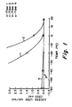
- FIG. 1 A comparison of low temperature fiber performance for blowable optical fibers comprising identical textured foam coatings but differing soft buffer configurations is provided by Fig. 1 of the drawings.
- prior art optical fibers 1 and 2 which are 125 ⁇ m fibers of single mode and multimode design, respectively, and which comprise conventional soft acrylate buffer coatings of approximately 60 ⁇ m thickness, exhibit very rapid and severe increases in excess loss for 1300 nm signal transmission at temperatures as high as 0 °C when provided with 150 ⁇ m overcoatings of foamed polyvinyl chloride polymer.
- multimode fiber 1 shows significant excess loss at 0 °C
- single mode fiber 2 shows a similar level of loss at -20 °C.
- Fibers 3 and 4 include low T g polymer overcoatings approximately 75 ⁇ m in thickness between the acrylate buffer and the 150 ⁇ m polyvinyl chloride foam overcoatings. Both fibers exhibit excess losses well below 0.3 db/km at all temperatures down to and including -60 °C, with single mode fiber 4 showing no significant excess loss at this temperature.
- Low elastic modulus coating materials having the requisite low T g required for good low temperature operation are commercially available.
- suitable coating materials are low T g acrylate coatings, low T g uv-curable silicone coatings, and low T g thermally curable silicone coatings.
- the silicone coatings are particularly preferred from the standpoints of low glass transition temperature, low elastic modulus, and good flame retardant characteristics. Also these coatings can be rapidly and conveniently liquid-applied to optical fibers as the fibers are manufactured, and they can be efficiently cured on the draw even at very high drawing and coating speeds.
- the thickness of the low T g elastomer or other polymer buffer coatings provided on optical fibers or in optical cables in accordance with the invention will be at least sufficient to protect the fibers alone or in cabled form from low-temperature microbending losses generated by pressure from the exteriorly applied textured coatings.
- low T g layer thicknesses of 50 ⁇ m or more on each fiber, or at least between each fiber and the textured exterior polymer coating subsequently applied to the fiber or cable are found to be satisfactory for this purpose.
- the location of the low T g polymer layer within the multilayer optical fiber or cable coating is not critical since the primary function of the layer is to insulate the fiber(s) from the textured exterior coating.
- the layer may be disposed directly on the fiber or instead over one or more primary buffer layers composed of other inorganic or organic coating materials previously applied to the fiber.
- the fiber or fibers may be provided with individual low T g polymer layers or encased in a low T g polymer matrix, with strengthening or other cabling elements positioned exteriorly of the layer and beneath the textured outer coating, or the low T g layer may be positioned immediately beneath the textured exterior coating.
- a textured exterior coating in accordance with the present description is meant an outer coating having a level of surface roughness sufficient for blow-in installation of the fiber or cable.
- a surface roughness of at least about 1 micron provides a satisfactorily textured coating, although much higher roughness levels are useful and are normally prefer strictlyred.
- the particularly preferred textured outer coating of the blowable optical fiber or cable of the invention is a foamed polyvinyl chloride coating.
- Foamed polyvinyl chloride formulations are well known, being currently marketed as flexible or rigid foamed materials of open-celled or closed-cell structure. These foams are widely used for a variety of applications including clothing, synthetic leather, upholstery, construction materials, and the like.
- Polyvinyl chloride foams are generally made from polyvinyl chloride plastisols, the principal constituents of which are a liquid plasticizer medium in which a finely divided normally solid polyvinyl chloride resin is dispersed. Additional components of such plastisols may include stabilizers, fillers, pigments and surfactants.
- Polyvinyl chloride plastisols may be foamed by mechanical means or by the inclusion of chemical foaming or so-called blowing agents therein, foaming being accomplished more or less contemporaneously with the curing process.
- the curing or conversion of the wet plastisols to solid thermoplastics is accomplished by heating to cause gelation and fusion of the plastisol. Heating causes the polyvinyl chloride resin particles in the sol to absorb plasticizer and swell, the swollen resin particles ultimately coalescing into a gel which is then fused and cooled to provide a durable thermoplastic material. If appropriate chemical foaming agents are added to the plastisol, the release of gas during the curing process produces a foamed rather than a dense thermoplastic product.
- Polyvinyl chloride plastisols suitable for the preparation of foamed coatings on optical fibers in accordance with the invention can be formulated from any of the commercially available plastisol preparations, or from plastisols made for the purpose by compounding together commercial PVC resins and plasticizers.
- Plasticizers used in the commercial formulations, and also suitable for the custom formulation of PVC plastisols include plasticizers such as the adipates, azelates, benzoates, chlorinated hydrocarbons, epoxy compounds, pthalates, isophthalates, terepthalates, phosphates, polyesters, and mixtures thereof.
- Chemical foaming agents to be mixed with the selected PVC plastisol formulation prior to coating application and curing in order to achieve the desired level of expansion of the coating are also readily commercially available.
- foaming agents particularly suitable for the expansion of PVC plastisols include the carbonates, azodicarbonamide, azobisisobutylronitrile and related compounds.
- the amount of foaming agent included in any particular formulation to achieve a selected level of expansion depends on the composition of the plastisol and foaming agent selected, but can readily be determined in each instance by routine experiment.
- a commercially available liquid PVC plastisol purchased as RDP-1267 plastisol from the Plastisols Division of the Dexter Corporation, Charlotte, North Carolina, is selected and a commercially available chemical blowing agent is added as a liquid to the plastisol in a concentration of about 1% by weight, with thorough blending to obtain a homogeneous mixture.
- the blowing agent selected is purchased as Celogen OT blowing agent from the Uniroyal Chemical Company, Inc. of Naugatuck, Connecticut.
- a length of commercially available optical fiber comprising a soft protective acrylate coating is drawn through an open cup applicator comprising the plastisol mixture.
- the plastisol-coated fiber is then immediately drawn through an oven operating at a temperature of about 450 °C wherein expansion and curing of the coating occurs within a few seconds.
- the coated fiber thus provided has an exterior textured foam PVC coating which is durable, adherent, light in weight, and of a surface texture well suited for blow-in installation of the fiber.
- the invention is particularly well suited for the continuous high speed manufacture of single blowable optical fibers from standard commercially available coated optical fibers by an overcoating process.
- This process can both adapt the single fibers for blow-in installation and provide buffer protection permitting dependable operation of the fiber over a wide temperature range.
- the overcoated single fibers are easily installable alone or in groups into blown fiber ductwork, utilizing conventional fiber blowing procedures and equipment. The following example illustrates an embodiment of the invention which achieves these results.
- a commercially available coated glass optical fiber comprising a glass core and cladding and a protective uv-cured acrylate coating covering the glass fiber is first selected for processing.
- the fiber is commercially available as Corguide R Code 1521 optical fiber from Corning Incorporated of Corning, NY.
- the glass core and cladding portion of the fiber have a diameter of 125 ⁇ m, with the protectively coated fiber having an overall diameter of about 250 ⁇ m.
- a silicone polymer is next selected to provide a low T g buffer layer on the coated fiber.
- the silicone selected for this overcoating or so-called upjacketing process is a thermally curable two-package silicone elastomer consisting of a silica-hydride-cured alkene, commercially available as SylgardTM 184 silicone elastomer system from the Dow Corning Corporation of Midland, Michigan. This elastomer has a glass-transition temperature of approximately -50 °C.
- the fiber is positioned on a tensioned payout and the fiber under tension is passed through a drying furnace.
- Adsorbed water and other low molecular weight volatile materials are driven from the protective acrylate coating by this treatment prior to the application of the silicone coating layer thereover.
- the coating consisting of a liquid mixture of the Part A and Part B packages of the elastomer system, is applied directly from a liquid coating die to the fiber at a liquid temperature of 15 °C. as the fiber is continuously drawn from the oven through the die.
- the coating die is a pressure coating die of the type disclosed in U. S. Patent No. 4,531,959.
- the die orifice and pressure of the liquid coating in the die are adjusted to provide a liquid coating approximately 75 ⁇ m in thickness on the surface of the coated fiber, such that the diameter of the silicone-overcoated fiber is approximately 400 ⁇ m.
- the applied liquid coating is converted to a silicone elastomer coating by drawing the liquid-coated fiber through a curing furnace to achieve cure.
- the curing furnace is maintained at a temperature of approximately 580°C, and is flushed with helium during curing to improve heat transfer to the coating. These conditions are effective to assure complete cure of the silicone coating layer at the point of exit of the fiber from the furnace.
- the elastomer-coated fiber thus provided is next overcoated with an expanded foam polyvinyl chloride polymer coating to furnish a textured surface thereon.
- the polymer coating is provided by the application to the fiber of a commercial foamable polyvinyl chloride plastisol formulation, purchased as Dexter RDP 1519-4 PVC plastisol from the Plastisols Division of the Dexter Corporation, Charlotte, North Carolina.
- This plastisol is formulated to contain about 2% by weight of a commercial foaming agent in its composition, that agent being identified as Celogen OT blow agent purchased from the Uniroyal Chemical Company, Inc., of Naugatuck, Connecticut.
- the commercial plastisol is continuously applied as a liquid overcoating to the fiber, utilizing the same procedure and apparatus as used to apply the silicone coating above, except that the two-package handling elements of the apparatus are not needed.
- the premixed plastisol is applied to the surface of the silicone elastomer overcoating layer as the overcoated fiber exits the curing furnace for the previously applied silicone coating.
- the plastisol is applied at a temperature of 15 °C, and at a pressure sufficient to provide a liquid plastisol coating approximately 50 microns in thickness on the surface of the coated fiber.
- the liquid-coated fiber is drawn through a second curing furnace to achieve cure and expansion (foaming) of the polyvinyl chloride coating.
- the curing furnace is maintained at a temperature of approximately 510°C, and is again flushed with helium gas for added heat transfer to the coating.
- the temperature of the polyvinyl chloride foam outer coating at the conclusion of the curing step is sufficiently high that the coating is soft and subject to surface damage on contact with other fibers or fiber collection and storage media. Accordingly, after the coated fiber exits the curing furnace but before contact with the fiber drawing tractors and collection reel, it is first cooled to rigidify the coating by passage through a fine water spray.
- An alternative and more efficient cooling method would be to use a conventional optical fiber cooling tube.
- the blowable optical fiber produced as described exhibits good blow-in characteristics and excellent low temperature optical performance. Friction test data obtained by the measurement of drag forces between similarly coated fibers and standard fiber duct materials indicate that such fibers are blow-installable over duct installation distances in excess of 500 meters, even at compressed gas pressures below 100 psig. Actual blow installation tests with fibers of this type confirm this desirable installation behavior.
- Fig. 1 of the drawing is a plot of excess signal loss (due to fiber microbending) versus temperature for various optical fibers.
- the loss characteristics shown in Fig. 1 for Fibers 3 and 4, which were coated in accordance with Example 1 above, are presently considered to be typical of the loss characteristics attainable in accordance with the invention.
- the performance advantage over prior art fibers 1 and 2 of Fig. 1 is readily apparent.
- a blowable optical fiber communication medium consisting of a lightweight optical cable (mini-cable), which cable includes multiple optical fibers in a multilayer polymer coating adapted for blow installation, can be made by a procedure similar to that disclosed in Example 1 above.
- An illustration of a suitable procedure for fabricating such a cable is provided by the following Example.
- acrylate-coated optical fibers having the same construction as the acrylate-coated fiber processed in Example 1 are selected for cabling. These fibers are mounted on separate tensioned payouts, and the fiber ends are collected and collimated in a four orifice guide die in preparation for coating.
- the collimated fibers in a square array (approximately 0.8 x 0.8 mm) are drawn through a drying furnace as in Example 1. This drying effects the removal of volatile materials from the acrylate coatings on the fibers prior to the application of silicone elastomer overcoatings thereto.
- Example 1 To apply a silicone elastomer coating to the fiber array, the array is next passed through a pressure coating die similar to that utilized in Example 1, except that the inlet and outlet orifices are enlarged to accept multiple fibers.
- the commercial two-package silicone elastomer used in Example 1 is again applied, with the same elastomer coating and curing conditions being maintained.
- the product of the elastomer coating process is a silicone-embedded fiber array of generally circular cross-section having a diameter of approximately 1 mm.
- the coated array is substantially free of internal and external coating voids and discontinuities, and the thickness of the elastomer layer provided exteriorly of the fibers in the array is in excess of about 50 ⁇ m.
- an overcoating of foamed PVC polymer is applied over the silicone elastomer, following the plastisol overcoating procedure substantially as described in Example 1.
- the same commercial PVC plastisol formulation is used, and is liquid applied to a thickness of approximately 50 ⁇ m.
- the plastisol layer is then foamed and cured by passage through a curing furnace as in Example 1, with the coated array thereafter being cooled, collected, and examined.
- the product of the above-described procedure is a flexible optical mini-cable comprising four elastomer-buffered optical fibers and having an outer diameter, with foamed PVC coating, of approximately 1.2 mm.
- the cable exhibits excellent blow-in and low temperature optical performance.
- Fig. 2 illustrates a blowable optical fiber similar in configuration to that of Example 1, incorporating a glass optical fiber 1 which has been provided with a covering buffer layer of a low T g polymer 2. Positioned over polymer layer 2 is exterior coating 3 which is a textured coating composed, for example, of a PVC foam.
- exterior coating 3 Positioned over polymer layer 2 is exterior coating 3 which is a textured coating composed, for example, of a PVC foam.
- the optical fiber comprising the low T g coating in accordance with the invention need not include a protective acrylate or other organic coating between the glass optical fiber and the low T g coating, as illustrated in Example 1.
- the low T g coating itself can readily perform both protective and low temperature buffering functions, if desired.
- Fig. 3 illustrates a design for a four-fiber blowable mini-cable similar to that described in Example 2, again comprising optical fibers 1 encapsulated in a low T g polymer matrix 2 such as a silicone elastomer, and covered by a textured outer coating 3 such as a PVC foam coating.
- a protective primary fiber coating such as the acrylate coating of the fibers of Example 2 is not required since the same function can be served by the silicone elastomer coating.
- Cable designs of this type may comprise from 1 to about 8 optical fibers, and are characterized in that the fibers are typically disposed in a fiber-parallel, bundled array.
- the soft buffer layer of low T g polymer can be an overcoating on the bundle but is most preferably provided, as in Fig. 3, as a polymer matrix encasing and supporting the glass optical fibers in a spaced bundled configuration.
- the invention is also applicable to the design and production of other blowable optical cable configurations.
- the procedure of Example 2 can readily be adapted to the production of an optical communication medium consisting of a blowable optical fiber ribbon cable.
- An illustration of a suitable process for blowable ribbon cable manufacture is more fully illustrated by the following example.
- An optical fiber ribbon cable of conventional design comprising a single one-dimensional or flat array of four optical fibers contained in a protective soft acrylate organic coating, may be selected for processing.
- a number of designs for these ribbon cables are known in the art, wherein the ribbon is provided simply by a fusing or bonding together of the coatings of individually coated fibers to form a flat multi-fiber bonded assembly.
- a flat array of four uncoated fibers may be configured and formed into coated ribbon by the application of an envelope of a low T g polymer to the array.
- the envelope provides a matrix which can serve both as a physical protective layer for the optical fibers and as a low T g buffer to provide the required low temperature optical performance.
- the ribbon cable, or group of ribbon cables, to be formed into a blowable ribbon cable includes only conventional soft acrylate or other primary layers, an overcoating of low T g polymer is provided thereon following the procedure of Example 2.
- the two-package silicone elastomer of Example 1 provides a suitable polymer for forming the requisite low T g layer on the ribbon(s).
- the resulting ribbon or ribbon group is next provided with a coating or jacketing layer of textured polymer, such as a foamed PVC polymer, covering the elastomer.
- a coating or jacketing layer of textured polymer such as a foamed PVC polymer, covering the elastomer.
- Application of this coating is preferably by means of a liquid PVC plastisol which is applied to the coated ribbon or ribbon group to form a liquid coating.
- the liquid coating is then heat-cured and expanded to provide a suitably textured foam coating.
- the commercial plastisol coating utilized to provide the blowable optical fiber of Example 1 is particularly useful for this purpose.
- a textured foamed PVC coating or jacket may be applied to the pre-coated ribbon or ribbon assembly by extrusion jacketing.
- the foamed textured jacket may comprise a loose-fitting foamed polymer tube or a tight-fitting or adherent coating, as desired.
- Figs. 4 and 5 of the drawing Examples of optical ribbon cables which may be produced in accordance with the above-described procedure are illustrated in Figs. 4 and 5 of the drawing.
- one or more 4-fiber arrays 1 are provided with a low T g silicone elastomer buffer material 2 providing both a protective layer on the fibers and a coating matrix providing a ribbon structure for the fiber array.
- the ribbon or ribbons are then covered with a foamed PVC outer coating 3 having low density and an appropriate textured surface.
- the cable of Fig. 5 comprises multiple fiber ribbons and is additionally provided with a pair of lightweight synthetic fiber ripcords 4 to facilitate cable stripping and ribbon separation.
- Figs. 4 and 5 are illustrative of the preferred ribbon cables of the invention which characteristically comprise, as a core element of each cable, at least one optical fiber ribbon including multiple optical fibers disposed in a flat, fiber-parallel array, with the low T g polymer providing both a buffer and a matrix around the fibers.
- the matrix encases and supports the fiber array in a flat ribbon configuration, while at the same time providing an interposing buffer layer between each of the fibers and the textured polymer outer layer on the cables.
- Optical bundle or ribbon cables of these designs, produced in accordance with the procedure of the above described examples, are light in weight and exhibit good blow-in characteristics in combination with excellent resistance to low temperature microbending losses.
Landscapes
- Physics & Mathematics (AREA)
- General Physics & Mathematics (AREA)
- Optics & Photonics (AREA)
- Engineering & Computer Science (AREA)
- Chemical & Material Sciences (AREA)
- Life Sciences & Earth Sciences (AREA)
- General Life Sciences & Earth Sciences (AREA)
- Manufacturing & Machinery (AREA)
- Chemical Kinetics & Catalysis (AREA)
- General Chemical & Material Sciences (AREA)
- Geochemistry & Mineralogy (AREA)
- Materials Engineering (AREA)
- Organic Chemistry (AREA)
- Optical Fibers, Optical Fiber Cores, And Optical Fiber Bundles (AREA)
- Light Guides In General And Applications Therefor (AREA)
Applications Claiming Priority (2)
| Application Number | Priority Date | Filing Date | Title |
|---|---|---|---|
| US07/419,674 US5062685A (en) | 1989-10-11 | 1989-10-11 | Coated optical fibers and cables and method |
| US419674 | 1989-10-11 |
Publications (2)
| Publication Number | Publication Date |
|---|---|
| EP0422764A2 true EP0422764A2 (fr) | 1991-04-17 |
| EP0422764A3 EP0422764A3 (en) | 1992-02-26 |
Family
ID=23663264
Family Applications (1)
| Application Number | Title | Priority Date | Filing Date |
|---|---|---|---|
| EP19900308883 Withdrawn EP0422764A3 (en) | 1989-10-11 | 1990-08-13 | Coated optical fibers and cables and method |
Country Status (6)
| Country | Link |
|---|---|
| US (1) | US5062685A (fr) |
| EP (1) | EP0422764A3 (fr) |
| JP (1) | JP3029855B2 (fr) |
| KR (1) | KR910008435A (fr) |
| AU (1) | AU6370090A (fr) |
| CA (1) | CA2020885A1 (fr) |
Cited By (9)
| Publication number | Priority date | Publication date | Assignee | Title |
|---|---|---|---|---|
| US5506711A (en) * | 1991-08-28 | 1996-04-09 | Hitachi, Ltd. | Star type multi-stage network |
| EP0752603A1 (fr) * | 1995-07-05 | 1997-01-08 | W.L. GORE & ASSOCIATES, INC. | Améliorations pour un matérial tampon avec des médias de transmission des signeaux optiques |
| WO2001073493A1 (fr) * | 2000-03-29 | 2001-10-04 | Emtelle Uk Limited | Cable de transmission de signaux |
| EP1403671A1 (fr) * | 2002-09-25 | 2004-03-31 | Fitel Usa Corporation | Câble à fibers optiques avec une direction de flexion réduite privilégiée |
| EP1331502A3 (fr) * | 2002-01-24 | 2004-10-13 | Alcatel | Câble optique contenant une unité optique entourée par des couches de gel |
| EP1550891A3 (fr) * | 2003-12-30 | 2005-07-27 | Furukawa Electric North America Inc. | Câbles à fibre optique améliorés |
| EP1577691A1 (fr) * | 2004-03-17 | 2005-09-21 | Furukawa Electric North America Inc. | Couches de protection améliorées pour câble à fibres optiques |
| EP2767520B1 (fr) * | 2013-02-19 | 2020-02-19 | Teldor Cables & Systems Ltd | Revêtement à double couleur de fibres optiques avec des encres durcissables aux UV |
| WO2020095315A1 (fr) | 2018-11-05 | 2020-05-14 | Sterlite Technologies Limited | Matériau matriciel pour rubans de fibres optiques enroulables |
Families Citing this family (67)
| Publication number | Priority date | Publication date | Assignee | Title |
|---|---|---|---|---|
| US5091053A (en) * | 1990-02-28 | 1992-02-25 | At&T Bell Laboratories | Matte finishes on optical fibers and other glass articles |
| FR2665266B1 (fr) * | 1990-07-27 | 1993-07-30 | Silec Liaisons Elec | Cable de telecommunication a fibres optiques. |
| GB2256604B (en) * | 1991-06-12 | 1995-04-19 | Northern Telecom Ltd | Plastics packaged optical fibre |
| US5249249A (en) * | 1991-08-27 | 1993-09-28 | Siecor Corporation | Cable utilizing multiple light waveguide stacks |
| US5173961A (en) * | 1991-12-12 | 1992-12-22 | Northern Telecom Limited | Telecommunications cable with ripcord removal for metal sheath |
| JP3314495B2 (ja) * | 1993-01-14 | 2002-08-12 | 住友電気工業株式会社 | テープ状光ファイバ心線 |
| US5392374A (en) * | 1993-04-28 | 1995-02-21 | Furon Company | Flame-retardant cable tubing bundle |
| US5473720A (en) * | 1993-07-28 | 1995-12-05 | At&T Corp. | Method for enhancing the pullout strength of polymer-coated optical fiber |
| GB2282897B (en) * | 1993-10-01 | 1996-10-23 | Pirelli General Plc | Optical fibre assembly with coating having projecting particulate material for blown installation |
| US5373578A (en) * | 1993-12-21 | 1994-12-13 | At&T Corp. | Strippable coating for optical fiber |
| US5442722A (en) * | 1994-07-25 | 1995-08-15 | Siecor Corporation | Optical fiber ribbon with zip cord |
| CA2131219C (fr) * | 1994-08-31 | 2003-01-28 | Tsuyoshi Nonaka | Fibre optique revetue |
| US5644670A (en) * | 1994-09-16 | 1997-07-01 | Toray Industries, Inc. | Broad bandwidth optical fibers, jacketed optical fibers and optical fiber cords |
| US6052503A (en) * | 1995-09-07 | 2000-04-18 | Dsm N.V. | Optical glass fiber ribbon assembly and radiation curable matrix forming composition |
| JPH09243884A (ja) * | 1996-03-12 | 1997-09-19 | Nippon Telegr & Teleph Corp <Ntt> | 光フラットケーブル |
| US5949940A (en) * | 1997-05-27 | 1999-09-07 | Corning Incorporated | Enhanced ribbon strippability using coating additives |
| US5729645A (en) * | 1996-08-13 | 1998-03-17 | The Trustees Of The University Of Pennsylvania | Graded index optical fibers |
| US6026207A (en) * | 1997-05-21 | 2000-02-15 | Alcatel | Black appearing color coating for optical fiber and method using same |
| FR2764994B1 (fr) * | 1997-06-19 | 1999-08-06 | Alsthom Cge Alcatel | Conducteur optique et ruban de conducteurs optiques |
| US6449412B1 (en) * | 1998-06-30 | 2002-09-10 | Corning Cable Systems Llc | Fiber optic ribbon interconnect cable |
| US6215934B1 (en) | 1998-10-01 | 2001-04-10 | Lucent Technologies, Inc. | Coated optical fiber with improved strippability |
| US6381390B1 (en) | 1999-04-06 | 2002-04-30 | Alcatel | Color-coded optical fiber ribbon and die for making the same |
| US6226431B1 (en) | 1999-06-29 | 2001-05-01 | Lucent Technology Inc. | Optical fiber cable |
| US6334016B1 (en) | 1999-06-30 | 2001-12-25 | Alcatel | Optical fiber ribbon matrix material having optimal handling characteristics |
| US6321012B1 (en) | 1999-08-30 | 2001-11-20 | Alcatel | Optical fiber having water swellable material for identifying grouping of fiber groups |
| US6421487B1 (en) | 2000-05-03 | 2002-07-16 | Alcatel | Reinforced buffered fiber optic ribbon cable |
| US7346244B2 (en) * | 2001-03-23 | 2008-03-18 | Draka Comteq B.V. | Coated central strength member for fiber optic cables with reduced shrinkage |
| US6876799B2 (en) | 2001-05-09 | 2005-04-05 | Alcatel | Gel-swellable layers on fibers, fiber ribbons and buffer tubes |
| DE10161045B4 (de) * | 2001-12-12 | 2005-05-04 | CCS Technology, Inc., Wilmington | Optische Festader und Verfahren zu deren Herstellung |
| AUPR949901A0 (en) * | 2001-12-17 | 2002-01-24 | University Of Sydney, The | Ring structures in optical fibres |
| US6768853B2 (en) * | 2002-06-21 | 2004-07-27 | Fitel Usa Corp. | Buffered optical fibers and methods of making same |
| GB0313018D0 (en) | 2002-08-10 | 2003-07-09 | Emtelle Uk Ltd | Signal transmitting cable |
| US20040052487A1 (en) * | 2002-09-13 | 2004-03-18 | Fitel U.S.A. Corporation | Foamed optical fiber coating and method of manufacture |
| US6904210B2 (en) * | 2002-09-17 | 2005-06-07 | Fitel Usa Corp. | Fiber optic ribbon and method of buffering loss |
| US20050282814A1 (en) * | 2002-10-03 | 2005-12-22 | Targegen, Inc. | Vasculostatic agents and methods of use thereof |
| US7231119B2 (en) * | 2002-12-19 | 2007-06-12 | Corning Cable Systems, Llc. | Dry fiber optic assemblies and cables |
| US6922511B2 (en) * | 2003-03-31 | 2005-07-26 | Corning Cable Systems Llc | Fiber optic assemblies and cables having subunits with a security feature |
| US20040208463A1 (en) * | 2003-04-15 | 2004-10-21 | Kyung-Tae Park | Cable for use in an air blowing installation and apparatus for manufacturing the same |
| US7050688B2 (en) | 2003-07-18 | 2006-05-23 | Corning Cable Systems Llc | Fiber optic articles, assemblies, and cables having optical waveguides |
| EP2543376A1 (fr) | 2004-04-08 | 2013-01-09 | Targegen, Inc. | Inhibiteurs de benzotriazine de kinases |
| US7652051B2 (en) | 2004-08-25 | 2010-01-26 | Targegen, Inc. | Heterocyclic compounds and methods of use |
| DE102006026222A1 (de) * | 2006-06-06 | 2007-12-13 | Siemens Ag | Fahrtschreiber für ein Kraftfahrzeug |
| US7463812B2 (en) * | 2007-01-19 | 2008-12-09 | Adc Telecommunications, Inc. | Overhead cable termination arrangement |
| US8081853B2 (en) * | 2007-11-09 | 2011-12-20 | Draka Comteq, B.V. | Single-fiber drop cables for MDU deployments |
| US8031997B2 (en) * | 2007-11-09 | 2011-10-04 | Draka Comteq, B.V. | Reduced-diameter, easy-access loose tube cable |
| US8145026B2 (en) * | 2007-11-09 | 2012-03-27 | Draka Comteq, B.V. | Reduced-size flat drop cable |
| US8041168B2 (en) * | 2007-11-09 | 2011-10-18 | Draka Comteq, B.V. | Reduced-diameter ribbon cables with high-performance optical fiber |
| DK2206001T3 (da) * | 2007-11-09 | 2014-07-07 | Draka Comteq Bv | Optisk fiber, der er modstandsdygtig over for mikrobøjning |
| US8165439B2 (en) * | 2007-11-09 | 2012-04-24 | Draka Comteq, B.V. | ADSS cables with high-performance optical fiber |
| US8041167B2 (en) | 2007-11-09 | 2011-10-18 | Draka Comteq, B.V. | Optical-fiber loose tube cables |
| US8467650B2 (en) * | 2007-11-09 | 2013-06-18 | Draka Comteq, B.V. | High-fiber-density optical-fiber cable |
| JP5588451B2 (ja) * | 2008-11-07 | 2014-09-10 | ドラカ・コムテツク・ベー・ベー | 小径光ファイバ |
| US8182880B2 (en) * | 2009-01-28 | 2012-05-22 | Honeywell International Inc. | Methods of manufacturing flexible insulated wires |
| US8582941B2 (en) * | 2009-02-16 | 2013-11-12 | Corning Cable Systems Llc | Micromodule cables and breakout cables therefor |
| US8625945B1 (en) * | 2009-05-13 | 2014-01-07 | Draka Comteq, B.V. | Low-shrink reduced-diameter dry buffer tubes |
| US8625944B1 (en) * | 2009-05-13 | 2014-01-07 | Draka Comteq, B.V. | Low-shrink reduced-diameter buffer tubes |
| US8655127B2 (en) * | 2010-12-17 | 2014-02-18 | Optical Cable Corporation | Rugged fiber optic cable |
| US9475239B2 (en) | 2011-11-01 | 2016-10-25 | Corning Cable Systems Llc | Cables with extruded access features and methods of making thereof |
| US9244237B2 (en) * | 2012-02-06 | 2016-01-26 | Tyco Electronics Corporation | Optical fiber with resilient jacket |
| CN103364899B (zh) * | 2013-07-02 | 2015-05-13 | 海门通能通讯科技有限公司 | 一种深海用应变传感测试用光缆 |
| NZ720105A (en) * | 2013-11-29 | 2019-06-28 | Prysmian Spa | High installation performance blown optical fibre unit, manufacturing method and apparatus |
| JP6620749B2 (ja) * | 2014-12-03 | 2019-12-18 | 住友電気工業株式会社 | 光ファイバ心線及び光ファイバテープ心線 |
| US9835812B2 (en) * | 2015-08-04 | 2017-12-05 | Corning Incorporated | Multi-optical fiber aggregate |
| US11249248B2 (en) * | 2018-10-29 | 2022-02-15 | Polyvalor, Limited Partnership | Method and system for fabricating an optical fiber device for shape sensing |
| JP7028816B2 (ja) * | 2019-03-11 | 2022-03-02 | 古河電気工業株式会社 | 光ファイバケーブル |
| WO2022005805A1 (fr) * | 2020-06-30 | 2022-01-06 | Corning Research & Development Corporation | Tube en mousse ayant un espace libre autour d'empilements de rubans de câble à fibres optiques |
| JP2023113107A (ja) * | 2022-02-02 | 2023-08-15 | 住友電気工業株式会社 | 光ファイバケーブルの製造方法および製造装置 |
Family Cites Families (12)
| Publication number | Priority date | Publication date | Assignee | Title |
|---|---|---|---|---|
| JPS587362Y2 (ja) * | 1980-10-24 | 1983-02-09 | 住友電気工業株式会社 | プラスチツクフアイバ |
| US4859023A (en) * | 1981-09-21 | 1989-08-22 | American Telephone And Telegraph Company, At&T Bell Laboratories | Sheathed optical fiber cable |
| EP0108590B1 (fr) * | 1982-11-08 | 1986-11-26 | BRITISH TELECOMMUNICATIONS public limited company | Fibres optiques de transmission |
| EP0157610B1 (fr) * | 1984-03-29 | 1989-09-13 | BRITISH TELECOMMUNICATIONS public limited company | Gainage pour fibres optiques |
| US4531959A (en) * | 1984-10-04 | 1985-07-30 | Corning Glass Works | Method and apparatus for coating optical fibers |
| US4690501A (en) * | 1985-07-08 | 1987-09-01 | Desoto, Inc. | Ultraviolet curable optical glass fiber coatings from acrylate terminated, end-branched polyurethane polyurea oligomers |
| GB8714226D0 (en) * | 1987-06-17 | 1987-07-22 | Bicc Plc | Optical fibre cables |
| GB8714640D0 (en) * | 1987-06-23 | 1987-07-29 | Bicc Plc | Optical fibre cables |
| NL8702395A (nl) * | 1987-10-08 | 1989-05-01 | Philips Nv | Optische vezel voorzien van een kunststofbedekking. |
| JPH0778564B2 (ja) * | 1988-03-09 | 1995-08-23 | 日立電線株式会社 | プラスチック光ファイバの製造方法 |
| US4848869A (en) * | 1988-08-08 | 1989-07-18 | Corning Incorporated | Method of coating and optical fiber comprising polyimide-silicone block copolymer coating |
| US4962992A (en) * | 1989-05-15 | 1990-10-16 | At&T Bell Laboratories | Optical transmission media and methods of making same |
-
1989
- 1989-10-11 US US07/419,674 patent/US5062685A/en not_active Expired - Lifetime
-
1990
- 1990-07-11 CA CA002020885A patent/CA2020885A1/fr not_active Abandoned
- 1990-08-13 EP EP19900308883 patent/EP0422764A3/en not_active Withdrawn
- 1990-09-29 KR KR1019900015733A patent/KR910008435A/ko not_active Withdrawn
- 1990-10-02 AU AU63700/90A patent/AU6370090A/en not_active Abandoned
- 1990-10-09 JP JP2269682A patent/JP3029855B2/ja not_active Expired - Fee Related
Cited By (16)
| Publication number | Priority date | Publication date | Assignee | Title |
|---|---|---|---|---|
| US5506711A (en) * | 1991-08-28 | 1996-04-09 | Hitachi, Ltd. | Star type multi-stage network |
| EP0529518A3 (en) * | 1991-08-28 | 1996-10-30 | Hitachi Ltd | Star type multi-stage network |
| EP0752603A1 (fr) * | 1995-07-05 | 1997-01-08 | W.L. GORE & ASSOCIATES, INC. | Améliorations pour un matérial tampon avec des médias de transmission des signeaux optiques |
| US5675686A (en) * | 1995-07-05 | 1997-10-07 | W. L. Gore & Associates, Inc. | Buffer material for optical signal transmission media |
| US6778744B2 (en) | 1999-10-08 | 2004-08-17 | Fitel Usa Corp. | Dielectric optical fiber cable having reduced preferential bending |
| US6778742B2 (en) | 2000-03-29 | 2004-08-17 | Emtelle Uk Limited | Signal transmitting cable |
| US6766090B2 (en) | 2000-03-29 | 2004-07-20 | Emtelle Uk Limited | Signal transmitting cable with outer covering that facilitates installation in a duct by fluid flow |
| WO2001073494A1 (fr) * | 2000-03-29 | 2001-10-04 | Emtelle Uk Limited | Cable a installer dans un conduit |
| WO2001073493A1 (fr) * | 2000-03-29 | 2001-10-04 | Emtelle Uk Limited | Cable de transmission de signaux |
| EP1331502A3 (fr) * | 2002-01-24 | 2004-10-13 | Alcatel | Câble optique contenant une unité optique entourée par des couches de gel |
| EP1403671A1 (fr) * | 2002-09-25 | 2004-03-31 | Fitel Usa Corporation | Câble à fibers optiques avec une direction de flexion réduite privilégiée |
| EP1550891A3 (fr) * | 2003-12-30 | 2005-07-27 | Furukawa Electric North America Inc. | Câbles à fibre optique améliorés |
| EP1577691A1 (fr) * | 2004-03-17 | 2005-09-21 | Furukawa Electric North America Inc. | Couches de protection améliorées pour câble à fibres optiques |
| EP2767520B1 (fr) * | 2013-02-19 | 2020-02-19 | Teldor Cables & Systems Ltd | Revêtement à double couleur de fibres optiques avec des encres durcissables aux UV |
| WO2020095315A1 (fr) | 2018-11-05 | 2020-05-14 | Sterlite Technologies Limited | Matériau matriciel pour rubans de fibres optiques enroulables |
| EP3891541A4 (fr) * | 2018-11-05 | 2022-11-02 | Sterlite Technologies Limited | Matériau matriciel pour rubans de fibres optiques enroulables |
Also Published As
| Publication number | Publication date |
|---|---|
| CA2020885A1 (fr) | 1991-04-12 |
| JP3029855B2 (ja) | 2000-04-10 |
| AU6370090A (en) | 1991-04-18 |
| US5062685A (en) | 1991-11-05 |
| KR910008435A (ko) | 1991-05-31 |
| JPH03164707A (ja) | 1991-07-16 |
| EP0422764A3 (en) | 1992-02-26 |
Similar Documents
| Publication | Publication Date | Title |
|---|---|---|
| US5062685A (en) | Coated optical fibers and cables and method | |
| CA1308585C (fr) | Cables a fibres optiques | |
| CA1321722C (fr) | Cables a fibres optiques | |
| EP0345968B1 (fr) | Fibres optiques revêtues | |
| US5201020A (en) | Reinforced protective tube for optical waveguide fibers | |
| US5148509A (en) | Composite buffer optical fiber cables | |
| EP0157610B1 (fr) | Gainage pour fibres optiques | |
| EP0527266B1 (fr) | Fibre optique avec couche tampon dénudable bien adjustée | |
| US4733941A (en) | Optical fibre comprising a synthetic resin cladding and method of and device for manufacturing such an optical fibre | |
| EP0853248B1 (fr) | Fibre optique avec couche tampon | |
| EP0867740B1 (fr) | Câble optique ascendant pour bâtiment à usage interne ou externe | |
| US5293442A (en) | Crush-resistant high-strength buffered optical waveguide fiber cable | |
| EP0752603A1 (fr) | Améliorations pour un matérial tampon avec des médias de transmission des signeaux optiques | |
| EP1403671B1 (fr) | Câble à fibres optiques ayant une direction de flexion réduite privilégiée | |
| HK1000421B (en) | Coated optical fibres | |
| GB1570624A (en) | Optical fibre transmission arrangements | |
| EP1376181B1 (fr) | Fibres optiques avec couche tampon et procédé de fabrication | |
| JPH09127346A (ja) | 多数のさや付き光ファイバーケーブルアセンブリ | |
| US11619787B1 (en) | Embedded strength member for optical fiber cables and manufacturing method thereof | |
| EP1072910A1 (fr) | Moyens pour mélanger des modes dans une fibre optique à revêtement tampon et procédé de fabrication | |
| EP0338854A2 (fr) | Corps à fibre optique | |
| Lawson | Contributions and effects of coatings on optical fibers |
Legal Events
| Date | Code | Title | Description |
|---|---|---|---|
| PUAI | Public reference made under article 153(3) epc to a published international application that has entered the european phase |
Free format text: ORIGINAL CODE: 0009012 |
|
| AK | Designated contracting states |
Kind code of ref document: A2 Designated state(s): DE ES FR GB IT NL |
|
| PUAL | Search report despatched |
Free format text: ORIGINAL CODE: 0009013 |
|
| AK | Designated contracting states |
Kind code of ref document: A3 Designated state(s): DE ES FR GB IT NL |
|
| STAA | Information on the status of an ep patent application or granted ep patent |
Free format text: STATUS: THE APPLICATION IS DEEMED TO BE WITHDRAWN |
|
| 18D | Application deemed to be withdrawn |
Effective date: 19920827 |