EP0422773A2 - Outils de coupe motorisés - Google Patents
Outils de coupe motorisés Download PDFInfo
- Publication number
- EP0422773A2 EP0422773A2 EP90309754A EP90309754A EP0422773A2 EP 0422773 A2 EP0422773 A2 EP 0422773A2 EP 90309754 A EP90309754 A EP 90309754A EP 90309754 A EP90309754 A EP 90309754A EP 0422773 A2 EP0422773 A2 EP 0422773A2
- Authority
- EP
- European Patent Office
- Prior art keywords
- cutting member
- blade
- cutting
- tool according
- teeth
- Prior art date
- Legal status (The legal status is an assumption and is not a legal conclusion. Google has not performed a legal analysis and makes no representation as to the accuracy of the status listed.)
- Granted
Links
Images


Classifications
-
- A—HUMAN NECESSITIES
- A01—AGRICULTURE; FORESTRY; ANIMAL HUSBANDRY; HUNTING; TRAPPING; FISHING
- A01G—HORTICULTURE; CULTIVATION OF VEGETABLES, FLOWERS, RICE, FRUIT, VINES, HOPS OR SEAWEED; FORESTRY; WATERING
- A01G3/00—Cutting implements specially adapted for horticultural purposes; Delimbing standing trees
- A01G3/04—Apparatus for trimming hedges, e.g. hedge shears
- A01G3/047—Apparatus for trimming hedges, e.g. hedge shears portable
- A01G3/053—Apparatus for trimming hedges, e.g. hedge shears portable motor-driven
-
- B—PERFORMING OPERATIONS; TRANSPORTING
- B23—MACHINE TOOLS; METAL-WORKING NOT OTHERWISE PROVIDED FOR
- B23D—PLANING; SLOTTING; SHEARING; BROACHING; SAWING; FILING; SCRAPING; LIKE OPERATIONS FOR WORKING METAL BY REMOVING MATERIAL, NOT OTHERWISE PROVIDED FOR
- B23D49/00—Machines or devices for sawing with straight reciprocating saw blades, e.g. hacksaws
- B23D49/10—Hand-held or hand-operated sawing devices with straight saw blades
- B23D49/16—Hand-held or hand-operated sawing devices with straight saw blades actuated by electric or magnetic power or prime movers
- B23D49/162—Pad sawing devices
-
- B—PERFORMING OPERATIONS; TRANSPORTING
- B27—WORKING OR PRESERVING WOOD OR SIMILAR MATERIAL; NAILING OR STAPLING MACHINES IN GENERAL
- B27B—SAWS FOR WOOD OR SIMILAR MATERIAL; COMPONENTS OR ACCESSORIES THEREFOR
- B27B17/00—Chain saws; Equipment therefor
- B27B17/0008—Means for carrying the chain saw, e.g. handles
-
- B—PERFORMING OPERATIONS; TRANSPORTING
- B27—WORKING OR PRESERVING WOOD OR SIMILAR MATERIAL; NAILING OR STAPLING MACHINES IN GENERAL
- B27G—ACCESSORY MACHINES OR APPARATUS FOR WORKING WOOD OR SIMILAR MATERIALS; TOOLS FOR WORKING WOOD OR SIMILAR MATERIALS; SAFETY DEVICES FOR WOOD WORKING MACHINES OR TOOLS
- B27G19/00—Safety guards or devices specially adapted for wood saws; Auxiliary devices facilitating proper operation of wood saws
- B27G19/006—Safety guards or devices specially adapted for wood saws; Auxiliary devices facilitating proper operation of wood saws for reciprocating saws
Definitions
- This invention relates to power-driven cutting tools.
- the invention relates to a power-driven cutting tool capable of use as a hedge trimmer or a saw or a combination of a hedge trimmer and a saw.
- Hedge trimmers and saws are known having two relatively reciprocatable blades.
- Power-driven saws for example, tree felling and logging saws are also known including one or more endless chains supporting saw teeth or endless chains in which individual links constitute saw teeth.
- a toothed blade or supported saw teeth will be referred to as a "cutting member”.
- a power driven cutting tool comprises a power source, a support means for supporting a cutting member (as herein before defined), means for placing the cutting member in at least two operating positions, relative to the support means and drive means for drivingly connecting the power source and the cutting member when the cutting member is disposed in a selected operating position whereby cutting can be performed with the cutting member disposed in anyone of the said operating positions.
- the power source may be an electric motor or an internal combustion engine.
- the cutting member comprises two blades each having cutting teeth and mounted for relative reciprocating movement to produce a cutting action resulting from the interaction of the teeth of each blade.
- EAch blade may be mounted for driving movement relative to the other.
- one blade may be fixed in which case the other blade is mounted for driving movement relative to the fixed blade.
- the blades may elongate with teeth disposed along each longitudinal edge.
- the blades may be formed as sectors of a circle.
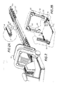
- the hedge trimmer/saw combination shwon has a support means S which supports a cutting member C .
- a power source not shown, in the form of an electric motor or internal combustion engine is mounted within the support means S .
- the cutting member C is mounted in a carrier bar B (see Figure 2A) consisting of a upper member B1 and a lower member B2 between which two elongate toothed blades C1 and C2 are supported for relative longitudinal and reciprocal movement.
- a safe;ty end-stop C3 of generally semi-circular shape constitutes a safety device to prevent those extreme teeth remote from the support means of the toothed blades C1, C2 from becoming entangled with an operators clothing or a portion of a hedge which is not to be trimmed or injuring a person.
- a portion C3 of the toothed blade C1 is formed with saw teeth C4. Further, teeth from blade C2 have been removed in the region the saw teeth C4 so that sawing of e.g. branches is effected simply by reciprocal movement of portion C3 and without cooperation of teeth on blade C2. If desired, however, teeth similar to C4 may be formed on a corresponding portion of the blade C2 but, is such a case the teeth on the respective blades C1 and C2 should be formed with an opposite "set" so as to clear saw dust from a saw kerf produced during sawing.
- a cover C5 which is suitably carried on the carrier bar B, is slid into the position shown in Figure 1A shielding the teeth C4.
- the support means S has two handles S1 and S2 and a hand shield S3.
- a main control switch S4 for controlling electric power supplied to the electric motor housed within the support means is mounted in the handle S1.
- four over-riding pressure pad switches S5 are positioned as indicated or the handle S2 so that an operator may, in the case of an emergency, readily cut-out supply of power to the electric motor.
- the spring biased linkage system L serves to connect each of the four pressure switches S5 and the switch S4.
- the handle S2 may be angularly displaceable fore- and aft- about axis A-A ( Figure 2B) via a restraining arrangement, not shown, so that in the event that an operator lunges or falls during operation of the cutting tool, the act of lunging or falling displaces the handle about the axis A-A to displace the linkage L and, thereby, cut-out power supply to the electric motor.
- Drive from the electric motor to the blades of the cutting member C may take the form of any conventional driving linkage to produce reciprocal movement of the cutting blades C1 and C2 such as an eccentric or cam drive.
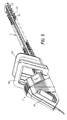
- Drive to the eccentric or cam drive may be via a system of bevel or spur gears G1/G2 as illustrated in Figure S1.
- the handle and support means 5 in which electric motor M is housed may be angularly displaced around axis Z-Z at a parting plane P-P in one or more indexed steps so as to change the angle of the plane containing the blades C1/C2 relative to the handle S1.
- a safety cut-out switch (not shown) is mounted in handle S2 so that, in the event of an emergency, an operator can activate either of the switches S2 or S4 to cut-out power supplied to the electric motor.
- the cutting member and associated eccentric drive may be mounted for displacement about axis Y-Y of bevel gear G2.
- the handle S1 and the blades C1/C2 will not be in alignment when viewed in the direction of arrow Q in Figure 5.
- the degree of angular displacement may be indexed in equal or unequal angular steps.
- FIGs 4A, 4B and 4C show in exploded detail, handle control switch arrangement for the handle S2.
- a non-cohesive, uncoated fibre optic F is used in conjunction with an LED transmitter-receiver combination.
- Ends F1 and F2 of the fibre optic F are optically connected to receivers R1 and R2 which, in turn, are mounted in optical alignment with LED transmitters T1 and T2.
- Resiliently mounted handle grips H1, H2 and H3 each include an arcuate extension H1A, H2A and H3A which bear against the optical fibre F when the optical fibre is in an "un-bent" or"non-distorted” attitude, that is when the cutting tool is operating normally under control of the main control switch S4 (see Figure 1).
- Figure 4B shows a handle S2 of similar shape to that shown on Figure 4A but, in this case power to the motor M is cut-out by a resistance controlled switch arrangement.
- the handle S2 is contructed from two interconnected components S2A and S2B and each component carries an associated conductive plastic plate S2A1 and S2B1 respectively. Gripping and squeezing together the two handle components S2A and S2B alters the resistance between the plates S2A1 and S2B1 which triggers the control switch.
- the two conductive plates S2A1 and S2B1 may be mounted in a mini computer which is operable according to a change in status of an electrical parameter (e.g. capacitive resistive, voltage or current) to thereby cut-out power to the motor M.
- an electrical parameter e.g. capacitive resistive, voltage or current
- Figure 4C shows a mechanical interlock system.
- the handle S2 houses three handle grips H10, H20 and H30.
- Handle grips H10 and H30 are angularly displaceable in the direction of arrows H40 and H50 about pivot points H60 and H70 respectively.
- Such angular displacement causes ends H80 and H90 of bell cranks H82 and H92 to be moved inwardly in the direction of arrows H81 and H91 to trip the control switch and cut-out power to the motor M.
- the handle grip H20 is mounted for sliding movement against a biasing force in the direction of arrow H22.
- the handle grips H20 has two arms H24 and H26 each carrying a respective pin H24A and H26A located, as shown in a triangular apertured member H24B and H26B. Displacement of the handle grip H20 in the direction the arrow H22 causes, the pins H24A and H26A to cooperate with surfaces H24C and H26C thereby causing the handle grips H10 and H30 to be angularly displaced in the direction of the arrows H40 and H50 to trip the control switch as previously described.
- handle S2 motor M and the cutting member C are mounted for pivotal movement about axis R and means (not shown) are provided for locking the pivotally movable parts in any desired angular position.
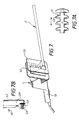
- FIGs 7, 7A and B show another embodiment of the cutting tool in which a safety switch S9 supported in handle S2 is operated against an air sack S10 as shown in Figure 7B. Compression of the air pack S10 in the direction of arrow A7 causes expansion of the sack against a spring biassed switch plunger SP to break an electrical connection between a switch not shown. Further, asshown in Figure 7A the teeth of the supper blade C1 are of narrower width then the teeth of blade C2. A similar toothed formation is shown in Figure 8 modified with individual steel teeth C8 in laid in the upper toother bar C1 which is made from a plastic material.
- Figure 8 shows a modification of the cutting member C in which the blade C1 is made from a plastics material having a skeleton of metal teeth C8 inlaid therein.
- Figures 9 and 9A show a fixed cutting blade C1 and a toothed cutting member C2 in the form of an endless chain which is supported on a carrier bar B and a multi faced idler pulley M disposed remotely from the handle S2 and support means S not shown.
- a modified, elliptically sectioned carrier bar B made in two parts B1 and B2 is shown in Figure 9B.
- the upper carrier bar B1 is formed with fixed teeth faced with steel insuits 55 whereas teeth equivalent to those on the cutting member C2 are mounted for reciprocating movement within the carrier bar B as previously described.
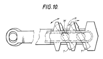
- Figure 10 shows an alternative eccentric device for the cutting teeth in which toothed elements T are carried on a toothed wheel W driven by a rack R which may be in the form of an endless chain or a reciprocatable toothed bar.
- the handle S1 may, of itself, be mounted for pivotal movement relative to the support means S and cutting blades considered together as a unitary structure.
- the handle S1 may be pivoted about an axis disposed in the line of arrow headed lines AA-AA or BB-BB in Figure 1.
Landscapes
- Life Sciences & Earth Sciences (AREA)
- Engineering & Computer Science (AREA)
- Mechanical Engineering (AREA)
- Forests & Forestry (AREA)
- Wood Science & Technology (AREA)
- Ecology (AREA)
- Biodiversity & Conservation Biology (AREA)
- Environmental Sciences (AREA)
- Scissors And Nippers (AREA)
- Harvester Elements (AREA)
- Lubricants (AREA)
- Shovels (AREA)
- Turning (AREA)
- Vending Machines For Individual Products (AREA)
Applications Claiming Priority (2)
| Application Number | Priority Date | Filing Date | Title |
|---|---|---|---|
| GB898920620A GB8920620D0 (en) | 1989-09-12 | 1989-09-12 | Improvements in and relating to power-driven cutting tools |
| GB8920620 | 1989-09-12 |
Publications (3)
| Publication Number | Publication Date |
|---|---|
| EP0422773A2 true EP0422773A2 (fr) | 1991-04-17 |
| EP0422773A3 EP0422773A3 (en) | 1991-12-11 |
| EP0422773B1 EP0422773B1 (fr) | 1995-11-22 |
Family
ID=10662947
Family Applications (1)
| Application Number | Title | Priority Date | Filing Date |
|---|---|---|---|
| EP90309754A Expired - Lifetime EP0422773B1 (fr) | 1989-09-12 | 1990-09-06 | Outils de coupe motorisés |
Country Status (8)
| Country | Link |
|---|---|
| EP (1) | EP0422773B1 (fr) |
| AT (1) | ATE130487T1 (fr) |
| AU (1) | AU6243990A (fr) |
| CA (1) | CA2025225A1 (fr) |
| DE (1) | DE69023736T2 (fr) |
| GB (1) | GB8920620D0 (fr) |
| IE (1) | IE903301A1 (fr) |
| ZA (1) | ZA907198B (fr) |
Cited By (19)
| Publication number | Priority date | Publication date | Assignee | Title |
|---|---|---|---|---|
| EP0469757A1 (fr) * | 1990-08-02 | 1992-02-05 | Black & Decker Inc. | Outil motorisé |
| EP0521806A1 (fr) * | 1991-07-02 | 1993-01-07 | OUTILS WOLF, S.à.r.l. | Outil motorisé portatif utilisable à deux mains, en particulier taille-haies |
| WO1993011658A1 (fr) * | 1991-12-18 | 1993-06-24 | Hans Locher | Dispositif pour la coupe d'objets longs, en particulier de plantes a tige |
| DE4224665A1 (de) * | 1992-07-25 | 1994-01-27 | Atlas Copco Elektrowerkzeuge | Scherblattträger einer Heckenschere |
| EP0622015A1 (fr) * | 1993-04-08 | 1994-11-02 | GARDENA Kress + Kastner GmbH | Cisaille à haies |
| EP0653274A1 (fr) * | 1993-11-13 | 1995-05-17 | Black & Decker Inc. | Protection pour outil à moteur |
| EP0696419A1 (fr) * | 1994-08-12 | 1996-02-14 | Black & Decker Inc. | Taille-haie avec assemblage de lames pour cisailler et scier |
| EP0750837A1 (fr) * | 1995-06-28 | 1997-01-02 | Robert Bosch Gmbh | Taille-haie |
| EP0890302A1 (fr) * | 1997-07-11 | 1999-01-13 | Scintilla Ag | Taille-haie |
| ES2130927A1 (es) * | 1995-11-17 | 1999-07-01 | Fornos Gimeno Domingo | Mejoras introducidas en el objeto de la patente de invencion principal 9502246(5) por maquina automatica y portatil multiuso para la poda, limpieza y derribo de pequeños frutos. |
| EP1334789A3 (fr) * | 2001-12-03 | 2005-03-09 | Milwaukee Electric Tool Corporation | Poignée pour scie alternative |
| WO2006056164A1 (fr) * | 2004-11-26 | 2006-06-01 | Dolmar Gmbh | Taille-haie a element de protection pour la lame |
| GB2406819B (en) * | 2003-10-08 | 2007-05-23 | Chris Vassiliades | A cutting tool |
| WO2011120534A1 (fr) * | 2010-03-30 | 2011-10-06 | Husqvarna Ab | Taille-haie |
| US9132491B2 (en) | 2008-03-07 | 2015-09-15 | Milwaukee Electric Tool Corporation | Portable battery-powered reciprocating saw |
| US9750197B2 (en) | 2015-09-09 | 2017-09-05 | Black & Decker Inc. | Hedgetrimmer with saw blade |
| US20170326721A1 (en) * | 2015-01-13 | 2017-11-16 | Yamabiko Corporation | Handle for electric tools and electric tool provided with same |
| US10159194B2 (en) | 2015-09-09 | 2018-12-25 | Black & Decker Inc. | Hedgetrimmer with saw blade |
| CN113711795A (zh) * | 2021-09-15 | 2021-11-30 | 李姣荣 | 一种市政绿化带修剪装置 |
Families Citing this family (9)
| Publication number | Priority date | Publication date | Assignee | Title |
|---|---|---|---|---|
| USD365256S (en) | 1994-06-14 | 1995-12-19 | Shop Vac Corporation | Hedge trimmer |
| US6108916A (en) | 1998-08-14 | 2000-08-29 | Milwaukee Electric Tool Corporation | Movable handle for a power tool |
| US6671969B2 (en) | 2001-12-18 | 2004-01-06 | Porter-Cable/Delta | Adjustable shoe for a reciprocating saw |
| JP2006321043A (ja) | 2005-05-17 | 2006-11-30 | Milwaukee Electric Tool Corp | 動力工具、バッテリ、充電器、およびそれらを動作させる方法 |
| JP2006325395A (ja) | 2005-05-17 | 2006-11-30 | Milwaukee Electric Tool Corp | 動力工具、バッテリ、充電器、およびそれらを動作させる方法 |
| US7752760B2 (en) | 2005-06-30 | 2010-07-13 | Black & Decker, Inc. | Portable trimmer having rotatable power head |
| DE102005053126A1 (de) | 2005-11-08 | 2007-05-10 | Andreas Stihl Ag & Co. Kg | Messerbalken einer durch einen Motor angetriebenen Heckenschere |
| WO2008061198A2 (fr) | 2006-11-15 | 2008-05-22 | Milwaukee Electric Tool Corporation | Outil électrique |
| EP2561748A1 (fr) * | 2011-08-25 | 2013-02-27 | Robert Bosch GmbH | Taille-haie |
Family Cites Families (8)
| Publication number | Priority date | Publication date | Assignee | Title |
|---|---|---|---|---|
| US1528731A (en) * | 1921-01-03 | 1925-03-03 | Raymond L Barker | Power-operated handsaw |
| US1779857A (en) * | 1929-06-24 | 1930-10-28 | Shafer Ira | Saw |
| US3143798A (en) * | 1962-05-04 | 1964-08-11 | Roy W Lundquist | Shrubbery trimmer |
| US3343613A (en) * | 1966-08-01 | 1967-09-26 | New Draulics Inc | Power operated tool |
| DE1582842B1 (de) * | 1967-03-14 | 1970-08-20 | Roth Kg Fritz | Motorisch angetriebenes Schneidgeraet fuer Rasen u.dgl. |
| DE3231899C2 (de) * | 1982-08-27 | 1986-07-17 | Metabowerke GmbH & Co, 7440 Nürtingen | Schutzvorrichtung für Heckenscheren |
| DE3531059A1 (de) * | 1985-08-30 | 1987-03-12 | Gardena Kress & Kastner Gmbh | Motorisch betriebenes handgeraet |
| US4651420A (en) * | 1986-05-22 | 1987-03-24 | Lonnecker Joseph C A | Universal vegetation cutter or UVC |
-
1989
- 1989-09-12 GB GB898920620A patent/GB8920620D0/en active Pending
-
1990
- 1990-09-06 EP EP90309754A patent/EP0422773B1/fr not_active Expired - Lifetime
- 1990-09-06 AT AT90309754T patent/ATE130487T1/de active
- 1990-09-06 DE DE69023736T patent/DE69023736T2/de not_active Expired - Fee Related
- 1990-09-11 ZA ZA907198A patent/ZA907198B/xx unknown
- 1990-09-11 IE IE330190A patent/IE903301A1/en unknown
- 1990-09-12 AU AU62439/90A patent/AU6243990A/en not_active Abandoned
- 1990-09-12 CA CA002025225A patent/CA2025225A1/fr not_active Abandoned
Cited By (27)
| Publication number | Priority date | Publication date | Assignee | Title |
|---|---|---|---|---|
| EP0469757A1 (fr) * | 1990-08-02 | 1992-02-05 | Black & Decker Inc. | Outil motorisé |
| EP0521806A1 (fr) * | 1991-07-02 | 1993-01-07 | OUTILS WOLF, S.à.r.l. | Outil motorisé portatif utilisable à deux mains, en particulier taille-haies |
| FR2678539A1 (fr) * | 1991-07-02 | 1993-01-08 | Wolf Outils | Outil motorise portatif utilisable a deux mains, en particulier taille-haie. |
| US5377480A (en) * | 1991-12-18 | 1995-01-03 | Locher; Hans | Apparatus for cutting down elongated standing crops, particularly stalk material |
| WO1993011658A1 (fr) * | 1991-12-18 | 1993-06-24 | Hans Locher | Dispositif pour la coupe d'objets longs, en particulier de plantes a tige |
| DE4224665A1 (de) * | 1992-07-25 | 1994-01-27 | Atlas Copco Elektrowerkzeuge | Scherblattträger einer Heckenschere |
| EP0622015A1 (fr) * | 1993-04-08 | 1994-11-02 | GARDENA Kress + Kastner GmbH | Cisaille à haies |
| EP0653274A1 (fr) * | 1993-11-13 | 1995-05-17 | Black & Decker Inc. | Protection pour outil à moteur |
| EP0696419A1 (fr) * | 1994-08-12 | 1996-02-14 | Black & Decker Inc. | Taille-haie avec assemblage de lames pour cisailler et scier |
| US5581891A (en) * | 1994-08-12 | 1996-12-10 | Black & Decker Inc. | Hedge trimmer with combination shearing and sawing blade assembly |
| AU699070B2 (en) * | 1994-08-12 | 1998-11-19 | Black & Decker Incorporated | Hedge trimmer with combination shearing and sawing blade assembly |
| EP0750837A1 (fr) * | 1995-06-28 | 1997-01-02 | Robert Bosch Gmbh | Taille-haie |
| ES2130927A1 (es) * | 1995-11-17 | 1999-07-01 | Fornos Gimeno Domingo | Mejoras introducidas en el objeto de la patente de invencion principal 9502246(5) por maquina automatica y portatil multiuso para la poda, limpieza y derribo de pequeños frutos. |
| EP0890302A1 (fr) * | 1997-07-11 | 1999-01-13 | Scintilla Ag | Taille-haie |
| EP1334789A3 (fr) * | 2001-12-03 | 2005-03-09 | Milwaukee Electric Tool Corporation | Poignée pour scie alternative |
| GB2406819B (en) * | 2003-10-08 | 2007-05-23 | Chris Vassiliades | A cutting tool |
| WO2006056164A1 (fr) * | 2004-11-26 | 2006-06-01 | Dolmar Gmbh | Taille-haie a element de protection pour la lame |
| US9132491B2 (en) | 2008-03-07 | 2015-09-15 | Milwaukee Electric Tool Corporation | Portable battery-powered reciprocating saw |
| US9233427B2 (en) | 2008-03-07 | 2016-01-12 | Milwaukee Electric Tool Corporation | Portable battery-powered reciprocating saw |
| WO2011120534A1 (fr) * | 2010-03-30 | 2011-10-06 | Husqvarna Ab | Taille-haie |
| CN102811605B (zh) * | 2010-03-30 | 2014-05-07 | 胡斯华纳有限公司 | 绿篱修剪机 |
| CN102811605A (zh) * | 2010-03-30 | 2012-12-05 | 胡斯华纳有限公司 | 绿篱修剪机 |
| US20170326721A1 (en) * | 2015-01-13 | 2017-11-16 | Yamabiko Corporation | Handle for electric tools and electric tool provided with same |
| US10569408B2 (en) * | 2015-01-13 | 2020-02-25 | Yamabiko Corporation | Handle for electric tools and electric tool provided with same |
| US9750197B2 (en) | 2015-09-09 | 2017-09-05 | Black & Decker Inc. | Hedgetrimmer with saw blade |
| US10159194B2 (en) | 2015-09-09 | 2018-12-25 | Black & Decker Inc. | Hedgetrimmer with saw blade |
| CN113711795A (zh) * | 2021-09-15 | 2021-11-30 | 李姣荣 | 一种市政绿化带修剪装置 |
Also Published As
| Publication number | Publication date |
|---|---|
| EP0422773B1 (fr) | 1995-11-22 |
| CA2025225A1 (fr) | 1991-03-13 |
| DE69023736D1 (de) | 1996-01-04 |
| EP0422773A3 (en) | 1991-12-11 |
| IE903301A1 (en) | 1991-04-10 |
| ZA907198B (en) | 1991-06-26 |
| AU6243990A (en) | 1991-03-21 |
| DE69023736T2 (de) | 1996-05-09 |
| GB8920620D0 (en) | 1989-10-25 |
| ATE130487T1 (de) | 1995-12-15 |
Similar Documents
| Publication | Publication Date | Title |
|---|---|---|
| EP0422773A2 (fr) | Outils de coupe motorisés | |
| KR0149244B1 (ko) | 복합작용식 수지형 가지치기 도구 | |
| CN113016384B (zh) | 园艺用修剪机 | |
| CN100394838C (zh) | 植物修剪装置 | |
| EP4265102A1 (fr) | Scie à chaîne | |
| US3657813A (en) | Powered tree pruning saw | |
| US4970791A (en) | Vegetation trimming apparatus for rounded configurations | |
| EP0267472A1 (fr) | Moyens de préhension d'un outil portable à moteur | |
| JPH0898627A (ja) | 剪断ブレード/鋸ブレードの組合せアセンブリを具えた生け垣用剪定器 | |
| EP1132183A2 (fr) | Machine pour le découpage sur trois côtés | |
| DE4027135C2 (de) | Stichsäge mit Drehzahlregelung | |
| DE60316633T2 (de) | Ausverriegelung für Schalter von Werkzeugen | |
| EP0469757B1 (fr) | Outil motorisé | |
| DE102020216563A1 (de) | Betätigungsvorrichtung für eine, insbesondere stabgebundene, Werkzeugmaschi-ne, Werkzeugmaschine, Verfahren zu einem Betätigen der Werkzeugmaschine und Schalteinheit für die Betätigungsvorrichtung | |
| EP1504659B1 (fr) | Mécanisme de verrouillage pour un assemblage de poignées pivotantes d'un outil motorisé | |
| GB2336987A (en) | An actuation and braking device for a motorised tool | |
| CN1328945C (zh) | 用于电动工具的启动机构及包含此启动机构的电动工具 | |
| GB2399269A (en) | Safety device for a cutting device | |
| EP1747710A1 (fr) | Arrangement d'élagage | |
| CN222827689U (zh) | 切割系统以及割草机 | |
| JP2003117267A (ja) | 手持ち式動力切断具 | |
| EP0546861B1 (fr) | Scie motorisée | |
| EP1212935A2 (fr) | Cisailles motorisées | |
| CN102658398B (zh) | 电动工具 | |
| US1838690A (en) | Motor hedge trimmer |
Legal Events
| Date | Code | Title | Description |
|---|---|---|---|
| PUAI | Public reference made under article 153(3) epc to a published international application that has entered the european phase |
Free format text: ORIGINAL CODE: 0009012 |
|
| AK | Designated contracting states |
Kind code of ref document: A2 Designated state(s): AT BE DE DK ES FR GB IT NL SE |
|
| PUAL | Search report despatched |
Free format text: ORIGINAL CODE: 0009013 |
|
| AK | Designated contracting states |
Kind code of ref document: A3 Designated state(s): AT BE DE DK ES FR GB IT NL SE |
|
| 17P | Request for examination filed |
Effective date: 19920204 |
|
| 17Q | First examination report despatched |
Effective date: 19921204 |
|
| RAP1 | Party data changed (applicant data changed or rights of an application transferred) |
Owner name: ELECTROLUX OUTDOOR PRODUCTS LIMITED |
|
| GRAA | (expected) grant |
Free format text: ORIGINAL CODE: 0009210 |
|
| AK | Designated contracting states |
Kind code of ref document: B1 Designated state(s): AT BE DE DK ES FR GB IT NL SE |
|
| PG25 | Lapsed in a contracting state [announced via postgrant information from national office to epo] |
Ref country code: IT Free format text: LAPSE BECAUSE OF FAILURE TO SUBMIT A TRANSLATION OF THE DESCRIPTION OR TO PAY THE FEE WITHIN THE PRE;WARNING: LAPSES OF ITALIAN PATENTS WITH EFFECTIVE DATE BEFORE 2007 MAY HAVE OCCURRED AT ANY TIME BEFORE 2007. THE CORRECT EFFECTIVE DATE MAY BE DIFFERENT FROM THE ONE RECORDED.SCRIBED TIME-LIMIT Effective date: 19951122 Ref country code: DK Effective date: 19951122 Ref country code: ES Free format text: THE PATENT HAS BEEN ANNULLED BY A DECISION OF A NATIONAL AUTHORITY Effective date: 19951122 |
|
| REF | Corresponds to: |
Ref document number: 130487 Country of ref document: AT Date of ref document: 19951215 Kind code of ref document: T |
|
| REF | Corresponds to: |
Ref document number: 69023736 Country of ref document: DE Date of ref document: 19960104 |
|
| ET | Fr: translation filed | ||
| PG25 | Lapsed in a contracting state [announced via postgrant information from national office to epo] |
Ref country code: SE Effective date: 19960222 |
|
| PG25 | Lapsed in a contracting state [announced via postgrant information from national office to epo] |
Ref country code: AT Effective date: 19960906 |
|
| PLBE | No opposition filed within time limit |
Free format text: ORIGINAL CODE: 0009261 |
|
| STAA | Information on the status of an ep patent application or granted ep patent |
Free format text: STATUS: NO OPPOSITION FILED WITHIN TIME LIMIT |
|
| PG25 | Lapsed in a contracting state [announced via postgrant information from national office to epo] |
Ref country code: BE Effective date: 19960930 |
|
| 26N | No opposition filed | ||
| BERE | Be: lapsed |
Owner name: ELECTROLUX OUTDOOR PRODUCTS LTD Effective date: 19960930 |
|
| PG25 | Lapsed in a contracting state [announced via postgrant information from national office to epo] |
Ref country code: NL Effective date: 19970401 |
|
| NLV4 | Nl: lapsed or anulled due to non-payment of the annual fee |
Effective date: 19970401 |
|
| REG | Reference to a national code |
Ref country code: GB Ref legal event code: IF02 |
|
| PGFP | Annual fee paid to national office [announced via postgrant information from national office to epo] |
Ref country code: GB Payment date: 20040625 Year of fee payment: 15 |
|
| PGFP | Annual fee paid to national office [announced via postgrant information from national office to epo] |
Ref country code: FR Payment date: 20040730 Year of fee payment: 15 |
|
| PGFP | Annual fee paid to national office [announced via postgrant information from national office to epo] |
Ref country code: DE Payment date: 20040930 Year of fee payment: 15 |
|
| PG25 | Lapsed in a contracting state [announced via postgrant information from national office to epo] |
Ref country code: GB Free format text: LAPSE BECAUSE OF NON-PAYMENT OF DUE FEES Effective date: 20050906 |
|
| PG25 | Lapsed in a contracting state [announced via postgrant information from national office to epo] |
Ref country code: DE Free format text: LAPSE BECAUSE OF NON-PAYMENT OF DUE FEES Effective date: 20060401 |
|
| GBPC | Gb: european patent ceased through non-payment of renewal fee |
Effective date: 20050906 |
|
| PG25 | Lapsed in a contracting state [announced via postgrant information from national office to epo] |
Ref country code: FR Free format text: LAPSE BECAUSE OF NON-PAYMENT OF DUE FEES Effective date: 20060531 |
|
| REG | Reference to a national code |
Ref country code: FR Ref legal event code: ST Effective date: 20060531 |