EP0422882B1 - Türscharnier - Google Patents
Türscharnier Download PDFInfo
- Publication number
- EP0422882B1 EP0422882B1 EP90311026A EP90311026A EP0422882B1 EP 0422882 B1 EP0422882 B1 EP 0422882B1 EP 90311026 A EP90311026 A EP 90311026A EP 90311026 A EP90311026 A EP 90311026A EP 0422882 B1 EP0422882 B1 EP 0422882B1
- Authority
- EP
- European Patent Office
- Prior art keywords
- spring
- shaft
- casing
- cam
- door
- Prior art date
- Legal status (The legal status is an assumption and is not a legal conclusion. Google has not performed a legal analysis and makes no representation as to the accuracy of the status listed.)
- Expired - Lifetime
Links
Images




Classifications
-
- A—HUMAN NECESSITIES
- A47—FURNITURE; DOMESTIC ARTICLES OR APPLIANCES; COFFEE MILLS; SPICE MILLS; SUCTION CLEANERS IN GENERAL
- A47K—SANITARY EQUIPMENT; ACCESSORIES THEREFOR, e.g. TOILET ACCESSORIES
- A47K13/00—Seats or covers for all kinds of closets
- A47K13/10—Devices for raising and lowering ; Collapsible or rotating seats or covers
-
- E—FIXED CONSTRUCTIONS
- E05—LOCKS; KEYS; WINDOW OR DOOR FITTINGS; SAFES
- E05D—HINGES OR SUSPENSION DEVICES FOR DOORS, WINDOWS OR WINGS
- E05D11/00—Additional features or accessories of hinges
- E05D11/06—Devices for limiting the opening movement of hinges
-
- E—FIXED CONSTRUCTIONS
- E05—LOCKS; KEYS; WINDOW OR DOOR FITTINGS; SAFES
- E05D—HINGES OR SUSPENSION DEVICES FOR DOORS, WINDOWS OR WINGS
- E05D11/00—Additional features or accessories of hinges
- E05D11/08—Friction devices between relatively-movable hinge parts
-
- E—FIXED CONSTRUCTIONS
- E05—LOCKS; KEYS; WINDOW OR DOOR FITTINGS; SAFES
- E05D—HINGES OR SUSPENSION DEVICES FOR DOORS, WINDOWS OR WINGS
- E05D11/00—Additional features or accessories of hinges
- E05D11/10—Devices for preventing movement between relatively-movable hinge parts
- E05D11/1028—Devices for preventing movement between relatively-movable hinge parts for maintaining the hinge in two or more positions, e.g. intermediate or fully open
- E05D11/1078—Devices for preventing movement between relatively-movable hinge parts for maintaining the hinge in two or more positions, e.g. intermediate or fully open the maintaining means acting parallel to the pivot
-
- E—FIXED CONSTRUCTIONS
- E05—LOCKS; KEYS; WINDOW OR DOOR FITTINGS; SAFES
- E05F—DEVICES FOR MOVING WINGS INTO OPEN OR CLOSED POSITION; CHECKS FOR WINGS; WING FITTINGS NOT OTHERWISE PROVIDED FOR, CONCERNED WITH THE FUNCTIONING OF THE WING
- E05F3/00—Closers or openers with braking devices, e.g. checks; Construction of pneumatic or liquid braking devices
- E05F3/14—Closers or openers with braking devices, e.g. checks; Construction of pneumatic or liquid braking devices with fluid brakes of the rotary type
-
- E—FIXED CONSTRUCTIONS
- E05—LOCKS; KEYS; WINDOW OR DOOR FITTINGS; SAFES
- E05F—DEVICES FOR MOVING WINGS INTO OPEN OR CLOSED POSITION; CHECKS FOR WINGS; WING FITTINGS NOT OTHERWISE PROVIDED FOR, CONCERNED WITH THE FUNCTIONING OF THE WING
- E05F3/00—Closers or openers with braking devices, e.g. checks; Construction of pneumatic or liquid braking devices
- E05F3/20—Closers or openers with braking devices, e.g. checks; Construction of pneumatic or liquid braking devices in hinges
-
- E—FIXED CONSTRUCTIONS
- E05—LOCKS; KEYS; WINDOW OR DOOR FITTINGS; SAFES
- E05Y—INDEXING SCHEME ASSOCIATED WITH SUBCLASSES E05D AND E05F, RELATING TO CONSTRUCTION ELEMENTS, ELECTRIC CONTROL, POWER SUPPLY, POWER SIGNAL OR TRANSMISSION, USER INTERFACES, MOUNTING OR COUPLING, DETAILS, ACCESSORIES, AUXILIARY OPERATIONS NOT OTHERWISE PROVIDED FOR, APPLICATION THEREOF
- E05Y2201/00—Constructional elements; Accessories therefor
- E05Y2201/20—Brakes; Disengaging means; Holders; Stops; Valves; Accessories therefor
- E05Y2201/21—Brakes
-
- E—FIXED CONSTRUCTIONS
- E05—LOCKS; KEYS; WINDOW OR DOOR FITTINGS; SAFES
- E05Y—INDEXING SCHEME ASSOCIATED WITH SUBCLASSES E05D AND E05F, RELATING TO CONSTRUCTION ELEMENTS, ELECTRIC CONTROL, POWER SUPPLY, POWER SIGNAL OR TRANSMISSION, USER INTERFACES, MOUNTING OR COUPLING, DETAILS, ACCESSORIES, AUXILIARY OPERATIONS NOT OTHERWISE PROVIDED FOR, APPLICATION THEREOF
- E05Y2201/00—Constructional elements; Accessories therefor
- E05Y2201/20—Brakes; Disengaging means; Holders; Stops; Valves; Accessories therefor
- E05Y2201/252—Type of friction
- E05Y2201/254—Fluid or viscous friction
-
- E—FIXED CONSTRUCTIONS
- E05—LOCKS; KEYS; WINDOW OR DOOR FITTINGS; SAFES
- E05Y—INDEXING SCHEME ASSOCIATED WITH SUBCLASSES E05D AND E05F, RELATING TO CONSTRUCTION ELEMENTS, ELECTRIC CONTROL, POWER SUPPLY, POWER SIGNAL OR TRANSMISSION, USER INTERFACES, MOUNTING OR COUPLING, DETAILS, ACCESSORIES, AUXILIARY OPERATIONS NOT OTHERWISE PROVIDED FOR, APPLICATION THEREOF
- E05Y2201/00—Constructional elements; Accessories therefor
- E05Y2201/20—Brakes; Disengaging means; Holders; Stops; Valves; Accessories therefor
- E05Y2201/262—Type of motion, e.g. braking
- E05Y2201/266—Type of motion, e.g. braking rotary
-
- E—FIXED CONSTRUCTIONS
- E05—LOCKS; KEYS; WINDOW OR DOOR FITTINGS; SAFES
- E05Y—INDEXING SCHEME ASSOCIATED WITH SUBCLASSES E05D AND E05F, RELATING TO CONSTRUCTION ELEMENTS, ELECTRIC CONTROL, POWER SUPPLY, POWER SIGNAL OR TRANSMISSION, USER INTERFACES, MOUNTING OR COUPLING, DETAILS, ACCESSORIES, AUXILIARY OPERATIONS NOT OTHERWISE PROVIDED FOR, APPLICATION THEREOF
- E05Y2201/00—Constructional elements; Accessories therefor
- E05Y2201/40—Motors; Magnets; Springs; Weights; Accessories therefor
- E05Y2201/47—Springs
- E05Y2201/49—Wrap springs
-
- E—FIXED CONSTRUCTIONS
- E05—LOCKS; KEYS; WINDOW OR DOOR FITTINGS; SAFES
- E05Y—INDEXING SCHEME ASSOCIATED WITH SUBCLASSES E05D AND E05F, RELATING TO CONSTRUCTION ELEMENTS, ELECTRIC CONTROL, POWER SUPPLY, POWER SIGNAL OR TRANSMISSION, USER INTERFACES, MOUNTING OR COUPLING, DETAILS, ACCESSORIES, AUXILIARY OPERATIONS NOT OTHERWISE PROVIDED FOR, APPLICATION THEREOF
- E05Y2999/00—Subject-matter not otherwise provided for in this subclass
Definitions
- This invention relates to a hinge which can be used for a door such as an ordinary swing door, or for a flap door including a vertically pivoting flap door typically used for a toilet lid or the like.
- Door hinges are known that utilize a viscous fluid, such as polyisobutylene or a similar high molecular viscous fluid, in combination with a spring in order to obtain a high resistance to abrupt motion of the door in one direction: use is made of the viscous shearing resistance of the viscous fluid and the torsional resistance of the spring to provide smooth and easy rotary movement.
- a viscous fluid such as polyisobutylene or a similar high molecular viscous fluid
- FR-A-1422988 discloses a hinge comprising a shaft for connecting to a door or the like, a casing to which the shaft is rotatably mounted, a movable cam slidably mounted on the shaft and being arranged to rotate therewith and a spring arranged to bias the movable cam axially along the shaft into face-to-face contact with a cam fixed to the casing, the contacting faces of the cams being profiled so that the cams lock the shaft relative to the casing at a predetermined angular position within a range of rotational angles of the shaft.
- the hinge is used for a door and the cams lock the door at predetermined position to prevent swinging movement.
- US-A-2814049 discloses a hinge for a toilet seat, in which a spring applies a torsional force to bias the seat in the opening direction.
- a hinge comprising a shaft for connecting to a door or the like, a casing to which the shaft is rotatably mounted, a movable cam slidably mounted on the shaft and being arranged to rotate therewith, and a spring arranged to bias the movable cam axially along the shaft into face-to-face contact with a cam fixed to said casing, the contacting faces of the cams being profiled so that the cams lock the shaft relative to the casing at a predetermined angular position within a range of rotational angles of the shaft, the hinge being characterised in that the spring is also arranged to apply a torsional force to the shaft to bias the shaft in a predetermined rotary direction relative to the casing.
- any external force applied to the door, to which the hinge is fitted serves as a rotary force for rotating the rotary shaft of the hinge either in the direction of opening or in the direction of closure of the door.
- the rotary shaft is rotated along with the movable cam which it carries, the spring fitted thereto is twisted to generate a torque for returning the door in the opposite direction.
- a flap door is provided with the hinge and rotates between a 0° angular position, or closed position, and a 110° angular position, or fully open position and that, when the flap door rotates with the rotary shaft of the hinge for closure, it twists the spring in the hinge to store torsional energy, then the spring naturally accelerates the opening motion of the door to make it easier for the user to open the door.
- the spring is also utilized to press the movable cam against the fixed cam: preferably the movable cam is provided with a number of ribs each having an inclined side wall, while the fixed cam is provided with the same number of grooves each having a matching inclined side wall.
- the movable cam is rotated until its ribs are located on the respective inclined side walls of the grooves of the fixed cam and then eventually comes to rest to lock the door at its maximum open position (110° angular position).
- the fixed and movable cams of the hinge are so configured that a torque is generated to further open the door once the door is opened to a given angular position.
- the performance of the hinge may be altered by modifying the configuration of the fixed and movable cams so that the door to which the hinge is fitted may be locked to a different angular position or to a fully closed position.
- a hinge comprising a shaft for connecting to a door or the like, a casing to which the shaft is rotatably mounted, a movable cam slidably mounted on the shaft and being arranged to rotate therewith and a spring disposed between the movable cam and a spring carrier fixed to the shaft to bias the movable cam axially along the shaft into face-to-face contact with a cam fixed to said casing, the hinge being characterised in that the spring has its opposite ends engaged respectively with the spring carrier and an axially extending groove formed in the casing, the spring being arranged to apply a torsional force to the shaft to bias the shaft in a predetermined rotary direction relative to the casing, the contacting faces of the cams are profiled so that a rotational torque is applied to the shaft by the axial compressive force of the spring when the shaft is within a range of rotational angles relative to the casing a member is rotatably mounted within the casing, a space between the
- any external force applied to the door, to which the hinge is fitted serves as a rotary force for rotating the rotary shaft of the hinge either in the direction of opening or in the direction of closure of the door.
- the spring carrier, with which the rotary shaft is engaged is engaged with or disengaged from the movable member by means of the spring clutch depending on the direction of rotation: thus the movable member does not rotate with the rotary shaft when the shaft rotates in a given direction and therefore no viscous shearing resistance is generated within the viscous fluid of the hinge.
- a flap door is provided with the hinge and rotates between a 0° angular position, or closed position, and a 110° angular position, or fully open position and that, when the flap door rotates with the rotary shaft and the spring carrier for closure, it twists the spring in the hinge to store torsional energy, then the spring naturally accelerates the opening motion of the door to make it easier for the user to open the door.
- the spring carrier and the movable member are engaged by means of the spring clutch during the closing motion, so that the movable member is rotated with the rotary shaft and the spring carrier to generate viscous shearing resistance in the viscous fluid contained in the space between the movable member and the casing of the hinge, so that the hinge operates as a damper that resists the rotation of the rotary shaft.
- the spring is also utilized to press the movable cam against the fixed cam, so that a torque is generated within the hinge to accelerate rotation of the shaft, preferably in the opening direction of the door, at least when the door has been opened to a predetermined angular position (e.g. 55° angular position) and until the door reaches its maximum angular position (110° angular position), where preferably it is locked.
- a predetermined angular position e.g. 55° angular position
- the door reaches its maximum angular position (110° angular position
- the performance of the hinge may be altered by modifying the configuration of the fixed and movable cams so that the door to which the hinge is fitted may be locked to a different angular position or to a fully closed position.
- the fixed cam and the movable cam of the hinge are so configured that, as the door to which the hinge is fitted comes close to its fully closed position, the door is subjected to a torque generated by the spring, trying to move the door in the other direction. Consequently the door is closed softly and smoothly.
- the spring presses the movable cam against the fixed cam so that the rotary shaft is subjected to a torque that accelerates the opening motion of the door in the initial stages of the opening operation to make it easier for the user to open it.
- Figs. 1 through 7 illustrate a first embodiment of the invention.
- horizontally placed cylindrical casing 1 comprises a projection 1b inwardly extended from the center of the inner surface of its end wall 1a and a threaded section 1c arranged at the inner periphery of its other end as well as a plurality of longitudinal grooves 1d... crossing said threaded section 1c.
- Horizontally placed cylindrical and movable shell 2 has a length which is approximately a half of the effective length of the inside of said casing 1 and an outer diameter which is slightly smaller than the inner diameter of the casing. Its end wall 2a is provided at the center of its outer surface with a bore 2b for receiving said projection 1b and on the outer periphery near its open end with a circular groove 2d for receiving a O-ring 3 so that the casing 1 and the movable shell 2 are axially rotatable relative to each other and the space A between them is airtightly sealed by the ring 3.
- the space A is thus defined by the end wall 1a and the peripheral wall 1e of the casing 1 and the end wall 2a and the peripheral wall 2e of the movable shell 2 and contains in it viscous fluid B that can be a high molecular viscous fluid such as polyisobutylene, pitch or highly viscous water glass.
- viscous fluid B can be a high molecular viscous fluid such as polyisobutylene, pitch or highly viscous water glass.
- Horizontally placed cylindrical spring carrier 4 comprises along its axis a cylindrical recess 4a and a polygonal hole 4b arranged side by side as well as a flange 4c on its outer periphery outwardly and radially projecting from the end closer to the recess 4a.
- Said spring carrier 4 is so arranged within said movable shell 2 that it is rotatable around the axis of the casing 1 by means of a spring one-way clutch 5 disposed between the recess 4a and the projection 2c of the movable shell 2.
- Said spring one-way clutch 5 is realized by winding a highly resilient steel wire having a rectangular or circular cross section to form a densely wound coil which presses itself against the inner peripheral surface of the recess 4a of said spring carrier 4, an end 5a of said clutch 5 projecting perpendicularly relative to its axis and received by a recess 2f formed on the projection 2c of the movable shell 2, the other end 5b being left free within the space provided for the clutch 5.
- the fixed cam 6 has a disc-like form with a considerable thickness and is provided with an axial through bore 6a and a plurality of axially extending ribs 6b... arranged on its outer periphery and received by the respective grooves 1d... of the casing for engagement, said fixed cam being securely held by a lid plate 7 which is screwed into the threaded section 1c of the casing 1 so that it is not axially movable nor rotatable around its axis.
- said fixed cam 6 is provided with three radially extending grooves 6c... arranged on its inner end surface 6d and equally spaced apart from one another, each of said grooves 6c... having an inclined side wall 6e between the inner end surface 6d of the cam 6 and the bottom of the groove.
- the rotary shaft 8 runs through the through bore 6a of the fixed cam 6 so that it is rotatable around the axis of the casing 1.
- Said rotary shaft 8 has a polygonal extension 8a, the end of which is received by the matching polygonal hole 4b of the spring carrier 4 for being tightly engaged therewith.
- the movable cam 9 also has a disc-like form with a considerable thickness and is provided with an axial and polygonal through bore 9a and three radially extending ribs 9c... arranged on an end surface 9b and equally spaced apart from one another, said ribs being engaged with the corresponding respective grooves 6c... of the fixed cam 6.
- each of the ribs 9c of the movable cam 9 has an inclined side wall 9d that matches the inclined side wall 6e of the fixed cam 6.
- the movable cam 9 is so arranged around said polygonal extension 8a of the rotary shaft 8 within the casing 1 and between the spring carrier 4 and the fixed cam 6 that it is not freely rotatable around the axis of the casing but axially slidable relative to the rotary shaft 8.
- the movable cam 9 rotates with the rotary shaft 8
- its ribs 9c... come into engagement with the corresponding respective grooves 6c... and then disengaged therefrom.
- the spring 10 is located within said casing 1 with its ends respectively abutting the flange 4c of the spring carrier 4 and a surface of said movable cam 9.
- the spring 10 is a coil spring which is so designed that it biases the rotary shaft 8 in one direction, resists any rotary movement of the shaft 8 in the other direction and at the same time press the movable cam 9 against the fixed cam 6. Therefore, when the spring 10 is not compressed, it has a length significantly greater than the distance between the flange 4c of the spring carrier 4 and the spring receiving surface of the movable cam 9.
- an end 10a of said spring 10 is received by the flange 4c of the spring carrier 4, while its other end 10b is slidably received by an axially extending groove 1f formed on the inner periphery 1e of the casing 1.
- the spring 10 may be forcibly twisted before its ends 10a and 10b are received by the respective receiving members so that the rotary shaft 8 is angularly biased by the spring by a certain angle from the angle of reference, or angle 0°.
- the portion of the rotary shaft 8 which is projecting from the casing 1 is rigidly connected to the center of rotation of a door or a similar item (not shown) so that an external turning effort is applied thereto.
- the spring one-way clutch 5 comes to closely contact with the inner peripheral surface of the recess 4a of the spring carrier 4 until the movable shell 2 is connected and rotates with the rotary shaft 8 and the spring carrier 4.
- the spring one-way clutch 5 plays the role of sustaining or disrupting the power transmission path constituted by the rotary shaft 8, the spring carrier 4 and the movable shell 2 depending on the direction of rotation of the rotary shaft 8 and the spring carrier 4.
- the rotary shaft 8 is connected to the toilet seat 11 and the casing is fitted to a toilet seat holding member, or a toilet bowl 12, in such a manner that the toilet seat 11 can be pivoted by an angle greater than 90° between its horizontal closed position, or angle 0° position, and its wide open position, or angle 110° position, as illustrated in Fig. 7.
- the opening movement of the toilet lid corresponds to the rotation of the rotary shaft 8 in the direction indicated by arrow D in Fig. 1.
- the spring carrier 4 When the toilet seat 11 is opened from its angle 0°position and the rotary shaft 8 is rotated in the direction of arrow D, the spring carrier 4 is also rotated in the direction of arrow D due to the fact that it is engaged with the rotary shaft 8, that the spring carrier 4 is biased in the direction of arrow D by the spring 10 and that the rotary shaft 8 is subjected to the resilient force of the spring 10 in the direction of arrow D by way of the spring carrier 4.
- the rotation of the spring carrier 4 results in reduction of the diameter of the spring one-way clutch 5, which in turn releases the tight connection of the spring one-way clutch 5 and the spring carrier 4 so that the connection between the spring carrier 4 and the movable shell 2 is also released to produce a clutch "disconnected" condition, where only the rotary shaft 8 and the spring carrier 4 are rotated in the direction of arrow D while the movable shell 2 is not rotated and therefore the shearing resistance of the viscous fluid B remains inoperative.
- the coil spring 10 Since, at this stage, the coil spring 10 is twisted further by the rotation of the spring carrier 4, it exerts a resistance against the rotary movement of the rotary shaft 8 to slow down the closing action of the toilet seat 11 until it smoothly and softly reaches the closed position, or angle 0° position.
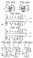
- the movable cam 9 is rotated in the direction of arrow C of Fig. 1 with the rotary shaft 8 from the position as indicated in Fig. 6(C), the ribs 9c... of the movable cam 9 climb up the respective inclined side walls 6e... of the grooves 6c... against the resilient force of the spring 10 until they get to the surface 6d of the fixed cam 6 to release the toilet seat 11 from the open and locked condition.
- Arrow E in Fig. 7 indicates the direction in which the resilient force of the spring 10 is applied to the rotary shaft 8 and therefore the toilet seat 11 and arrow F indicates the direction of viscous shearing resistance of the viscous fluid B, whereas arrow G shows the direction where no viscous shearing resistance is traced.
- Figs. 8 through 12 illustrate a second embodiment of the invention.
- casing 1 comprises a cylindrical projection 1g standing from the center of its end 1a, an axial bore 1h being formed along the axis of said cylindrical projection 1g.
- Rotary shaft 8 runs through the axial through bore 6a of a fixed cam 6 which is rigidly held by the casing 1 so that the rotary shaft 8 and the casing 1 are concentric relative to each other.
- a spring 10 is arranged within the casing 1 between the inner surface of the end 1a and the inner surface of the movable cam 9, its one end 10a being bent to form a hook and held within a recess 1i formed on said end 1a, its other end 10b being received by an axial groove 8b formed on said movable cam 9 so that it is slidable only in the axial direction and therefore said spring 10 may be twisted further when the rotary shaft 8 is rotated in the direction of arrow C in Fig. 8.
- the effective length of said spring 10 is so selected that it is longer than the distance between the inner surface of the end 1a of the casing 1 and the inner surface of the movable cam 9 and therefore the movable cam 9 is constantly biased toward the fixed cam 6 by the spring 10.
- the fixed cam 6 has on its surface facing the movable cam 9 three radial grooves 6e... which are spaced apart from one another by the same angle, or 120°, and has a substantially semicircular cross section, while the movable cam 9 is provided with three corresponding radial ribs 9c... which are also equally spaced apart from one another and has a substantially semicircular cross section so that they may be engaged with and disengaged from the respective grooves 6e....
- this second embodiment is not provided with a movable shell 2, nor with a spring carrier 4 and therefore not with a viscous fluid B.
- the rotary shaft 8 is connected to the toilet seat 11 in a manner similar to that of the first embodiment.
- the ribs 9c... of the movable cam 9 are fully received by the respective grooves 6c... of the fixed cam 6 for mutual engagement of the movable and fixed cams 6 and 9 and the toilet seat 11 is locked to its position (angle 110° position).
- the ribs 9c... of the movable cam 9 are released from the engagement with the respective grooves 6c of the fixed cam 6 by the rotary movement of the movable cam 9 in the direction of arrow C against the biasing force of the spring 10 so that the toilet seat 11 is unlocked from its open position.
- Figs. 13 through 17 illustrate a third embodiment of the invention.
- This embodiment differs from the first embodiment in that the fixed cam 6 and the movable cam 9 have profiles which are different from those of the fixed and movable cams 6 and 9 of the first embodiment.
- this third embodiment is configured similarly as the first embodiment.
- the rotary shaft 8 is rotated in the direction of arrow C to twist further the spring 10 as in the case of the first embodiment so that the door 11a is closed smoothly and softly by the resilient force of the spring and the viscous shearing resistance of the viscous fluid in the hinge assembly that resist any abrupt closing movement of the door 11a.
- a hinge having a configuration which is essentially identical with that of the above first embodiment but differs from it in the sense as described below.
- a hinge according to the fourth embodiment of the invention comprises a relatively thick disc-shaped fixed cam 6 having a central circular axial through bore 6a and a plurality of axial ribs 6b... arranged on its outer peripheral surface, said axial ribs 6b... being received by corresponding respective axial grooves 1d... of a casing 1 and rigidly held there by means of a lid plate 7 which is screwed into the threaded section 1c of the casing 1 so that it may not axially move nor rotate.
- the inner surface 6d is realized in the form of an inclined surface 6e and a perpendicular wall 6h whose height is defined by the highest portion 6f and the lowest portion 6g of the inclined surface 6e.
- the hinge also comprises a relatively thick disc-shaped movable cam 9 having a central polygonal axial through bore 9a and its outer surface 9d is realized in the form of an inclined surface and a perpendicular wall 9g that respectively corresponds to the inclined surface 6e and the perpendicular wall 6h of the fixed cam 6, the height of which is defined by the highest portion 9e and the lowest portion 9f of the inclined surface 9d.
- Said movable cam 9 is fitted to polygonal extension 8a of a rotary shaft 8 in such a manner that it is axially movable but not peripherally so that it freely rotates with the rotary shaft 8 and may be engaged with or disengaged from the fixed cam 6 as it axially moves as illustrated in Fig. 19(a) and (b)
- a hinge according to the fourth embodiment of the invention operates in the following manner.
- a first open position S2 e.g. opened by 55°
- the highest portion 9e of the movable cam 9 is moved to the inclined surface 6e of the fixed cam 6 as shown in Fig. 19(a) and a torque is generated to open the toilet seat 11 because of the effect of the spring 10 as a compression spring and the shape of the two cams 6 and 9 so that the movable cam 9 is rotated in the direction of arrow D of Fig. 19(b) through the mutual action of the two inclined surfaces 6d and 9c until the perpendicular walls 6h and 9g of the cams 6 and 9 abut each other. Consequently, the toilet seat 11 is opened up to a full open position S3 and locked there.
- a hinge having a configuration which is essentially identical with that of the first embodiment described earlier but differs from it in the sense as stated below.
- a hinge according to the fifth embodiment of the invention comprises a relatively thick disc-shaped fixed cam 6 having three radial grooves 6c... on its inner surface 6d which are equally spaced apart from one another, one of the side walls of each of said grooves 6c... being formed as an inclined side wall 6e stretching from the inner surface 6d down to the bottom of the groove 6c, the other side wall being a perpendicular side wall 6i.
- the movable cam 9 of the hinge is realized in the form of a relatively thick disc having a polygonal central axial through bore 9a and three radially extending ribs 9c... on its outer surface which are equally spaced apart from one another.
- Each of the ribs 9c... has a profile that corresponds to that of the groove 6c that receives it although the width of the former is a little smaller than that of the groove 6c so that the movable cam 9 may be slightly rotated even when the ribs 9c... are fully engaged with the respective grooves 6c....
- Each of said ribs 9c... has an inclined side wall 9d that matches the corresponding inclined side wall 6e of the fixed cam 6 and a perpendicular side wall 9h that also matches the corresponding perpendicular side wall 6i of the fixed cam 6.
- Said movable cam 9 is fitted to an polygonal extension 8a of the rotary shaft 8 between the spring carrier 4 and the fixed cam 6 in such a manner that it is axially slidable but peripherally not slidable relative to the rotary shaft 8 and that it is rotatable with the rotary shaft 8 so that it may be engaged with and disengaged from the fixed cam 6 as illustrated in Figs. 22(a) and (b).
- a hinge according to the fifth embodiment of the invention operates in the following manner.
- the resilient force of the spring 10 deters any abrupt motion of the toilet seat 11 so that it is moved smoothly and softly to its closed position S1.
- the ribs 9c... of the movable cam 9 are pressed hard against the inner surface 6d of the fixed cam 6 by the spring 10.
- the pressure of the spring 10 acts as a braking force for the closing movement of the toilet seat 11 at the final stages of its closure.
- the toilet seat 11 is smoothly and softly moved from the open position S4 in Fig. 23 to the closed position S1.
- a door using a hinge according to claim 1 and comprising a spring whose resilient force constantly biases the door to open can be either opened to any desired angle or closed and sustained there under a locked condition when the rotary shaft of the hinge is firmly connected to the door, it can be used for a flap door or another vertically rotatable door such as a toilet lid to sustain the door to an open position under a locked condition even if the resilient force of the spring is nullified at that position and the door is liable to be pushed back by an obstacle such as a wire located behind the toilet assembly comprising the lid.
- the door is protected against any turning effort and other forces which are unintentionally applied to the door and can be kept to an open position, although it can be turned back to the closed position smoothly and softly against the resilient force of the spring it comprises and locked to that position so that any abrupt motion of the door may be eliminated.
- the hinge since the hinge may be so designed that it can generate a torque for both opening and closing the door by altering the profile of the fixed and movable cams, there may be provided, if necessary, a door that can be opened or closed from a certain intermediary position to a fully open or closed position and locked there. Since a single spring can meet all these requirements, the hinge is configured with a very simple structure and therefore can be prepared at a low cost.
- a flap door or a toilet lid provided with a hinge according to claim 2 and having a rotary shaft rigidly connected to the door can be opened to any angular position by the spring it comprises that operates as a torsion spring to that position and thereafter acts as a compression spring for pressing a movable cam against a fixed cam to generate a torque for further opening the door so that the door may be turned smoothly and softly to its fully open position and locked there. Then, the door may be smoothly and softly turned back to its closed position thanks to the torque generated within the hinge for opening the door, the resilient force of the spring and the viscous shearing resistance of the viscous fluid it contains that tend to offset the abrupt closing motion of the door.
- the door may be so designed as to be opened to any desired angular position by altering the profile of the fixed and movable cams, the door may perform any selected action in terms of opening and closing.
- a single spring is used as both a torsion spring and a compression spring, the hinge is configured with a very simple structure and therefore can be prepared at a low cost.
- the closing action of the door is also soft and smooth because the torque for rotating the rotary shaft in the direction of opening the door decelerates the closing motion of the door.
- the hinge is configured with a very simple structure and therefore can be prepared at a low cost.
Landscapes
- Engineering & Computer Science (AREA)
- Mechanical Engineering (AREA)
- Health & Medical Sciences (AREA)
- Public Health (AREA)
- Pivots And Pivotal Connections (AREA)
- Toilet Supplies (AREA)
- Closing And Opening Devices For Wings, And Checks For Wings (AREA)
- Hinge Accessories (AREA)
Claims (3)
- Scharnier, das eine Achse (8) zum Verbinden mit einer Tür oder dergleichen, eine Gehäuse (1), an dem die Achse (8) drehbar befestigt ist, ein bewegliches Nockenelement (9), das gleitbar auf der Achse angebracht und so angeordnet ist, daß es sich mit derselben dreht, und eine Feder (10) aufweist, die so angeordnet ist, daß sie das bewegbare Nockenelement (9) axial entlang der Achse (8) in Flächean-Fläche-Berührung mit einem Nocken (6), der am Gehäuse (1) befestigt ist, vorspannt, wobei die sich berührenden Flächen der Nocken (6,9) so profiliert sind, daß die Nocken (6,9) die Achse (8) relativ zum Gehäuse (1) bei einer vorbestimmten Winkelstellung innerhalb eines Bereiches von Drehwinkeln der Achse fixieren, wobei das Scharnier dadurch gekennzeichnet ist, daß die Feder (10) auch so angeordnet ist, daß sie eine Torsionskraft auf die Achse (8) ausübt, um die Achse (8) in eine vorbestimmte Drehrichtung relativ zum Gehäuse (1) vorzuspannen.
- Scharnier, das eine Achse (8) zum Verbinden mit einer Tür oder dergleichen, ein Gehäuse (1), an dem die Achse (8) drehbar angebracht ist, ein bewegbares Nockenelement (9), das gleitbar auf der Achse angebracht ist und so angeordnet ist, daß es mit derselben sich dreht, und eine Feder (10) aufweist, die zwischen den bewegbaren Nockenelement (9) und einem Federträger (4), der an der Achse (8) befestigt ist, angeordnet ist, um das bewegbare Nockenelement (9) axial entlang der Achse (8) in Fläche-an-Fläche-Berührung mit einem Nocken (6), der am Gehäuse (1) befestigt ist, vorzuspannen, wobei das Scharnier dadurch gekennzeichnet ist, daß die Feder (10) mit ihren gegenüberliegenden Enden mit dem Federträger (4) und einer sich axial erstreckenden Nut (1F) in Eingriff steht, die in dem Gehäuse (1) ausgebildet ist, wobei die Feder (10) so angeordnet ist, daß sie eine Drehkraft auf die Achse (8) ausübt, um die Achse (8) in einer vorbestimmten Drehrichtung relativ zum Gehäuse (1) vorzuspannen, wobei die sich berührenden Flächen der Nocken (6,9) so profiliert sind, daß auf die Drehachse (8) durch die axiale Druckkraft der Feder (10) ein Drehmoment ausgeübt wird, wenn sich die Achse (8) innerhalb eines Bereiches von Drehwinkeln relativ zum Gehäuse (1) befindet, daß ein Glied (2) innerhalb des Gehäuses (1) drehbar angebracht ist, wobei ein Raum (A) zwischen dem bewegbaren Element (2) und dem Gehäuse (1) mit einem viskosen Fluid (B) gefüllt ist, und daß eine Federkupplung (5) zwischen dem bewegbaren Element (2) und dem Federträger (4) so verbunden ist, daß sich das bewegbare Element (2) mit der Achse (8) nur in einer Richtung der Achsendrehung dreht.
- Scharnier nach Anspruch 2, dadurch gekennzeichnet, daß die sich berührenden Flächen Nocken (6,9) so profiliert sind, daß das Drehmoment auf die Achse (8) in einem anfänglichen Abschnitt der Drehung der Achse (8) relativ zum Gehäuse (1) ausgeübt wird.
Applications Claiming Priority (6)
| Application Number | Priority Date | Filing Date | Title |
|---|---|---|---|
| JP26471689A JPH0678701B2 (ja) | 1989-10-11 | 1989-10-11 | ヒンジ |
| JP264716/89 | 1989-10-11 | ||
| JP284550/89 | 1989-10-31 | ||
| JP284551/89 | 1989-10-31 | ||
| JP28455089A JPH0678704B2 (ja) | 1989-10-31 | 1989-10-31 | 扉等用ダンパー |
| JP28455189A JPH0678705B2 (ja) | 1989-10-31 | 1989-10-31 | 扉等用ダンパー |
Publications (2)
| Publication Number | Publication Date |
|---|---|
| EP0422882A1 EP0422882A1 (de) | 1991-04-17 |
| EP0422882B1 true EP0422882B1 (de) | 1994-12-21 |
Family
ID=27335323
Family Applications (1)
| Application Number | Title | Priority Date | Filing Date |
|---|---|---|---|
| EP90311026A Expired - Lifetime EP0422882B1 (de) | 1989-10-11 | 1990-10-09 | Türscharnier |
Country Status (7)
| Country | Link |
|---|---|
| US (1) | US5109571A (de) |
| EP (1) | EP0422882B1 (de) |
| KR (1) | KR960000116B1 (de) |
| AU (1) | AU624027B2 (de) |
| CA (1) | CA2027272C (de) |
| DE (1) | DE69015309T2 (de) |
| IE (1) | IE62384B1 (de) |
Families Citing this family (102)
| Publication number | Priority date | Publication date | Assignee | Title |
|---|---|---|---|---|
| JP2534114Y2 (ja) * | 1991-09-30 | 1997-04-30 | 日本電気株式会社 | 折畳型電子機器の構造 |
| US5274882A (en) * | 1992-03-03 | 1994-01-04 | Ericsson Ge Mobile Communications Inc. | Hinge mechanism |
| ES2063652B1 (es) * | 1992-05-29 | 1997-04-01 | Amasuno Carlos Martin | Perfeccionamientos en la fabricacion de bisagras. |
| DE9300903U1 (de) * | 1993-01-23 | 1993-03-11 | Fischer, Friedrich, 2050 Hamburg | Spiralfedersystem |
| US5419013A (en) * | 1993-12-10 | 1995-05-30 | Hsiao; Chun-Sung | Hydraulic hinge having rotatable shaft and linearly movable plug forming fluid chambers |
| US5628089A (en) * | 1995-05-18 | 1997-05-13 | Motorola, Inc. | Radiotelephone having a self contained hinge |
| DE19518400A1 (de) * | 1995-05-19 | 1996-11-21 | Friedrich Fischer | Vorrichtung zur Kraftspeicherung in Federspeichern |
| US5606773A (en) * | 1995-11-14 | 1997-03-04 | Pike Machine Products, Inc. | Reversible hinge assembly |
| US5673957A (en) * | 1996-02-01 | 1997-10-07 | Moo; Hing Fai | Auxilary sun visor |
| FI961587L (fi) * | 1996-04-11 | 1997-10-12 | Nokia Mobile Phones Ltd | Saranamekanismi kokoontaitettavan laitteen kahden osan kiinnittämiseksi kääntyvästi toisiinsa |
| IT239720Y1 (it) * | 1996-04-19 | 2001-03-13 | Fiat Auto Spa | Dispositivo meccanico per controllare il movimento di apertura di unosportello. |
| US6033015A (en) * | 1996-07-01 | 2000-03-07 | Lear Corporation | Armrest cover positioning mechanism |
| JPH10131947A (ja) * | 1996-10-28 | 1998-05-22 | Kato Electrical Mach Co Ltd | 複合トルクヒンジ |
| NL1006535C1 (nl) * | 1996-11-19 | 1998-05-20 | Scambia Ind Dev Ag | Inklapbare draaginrichting voor een contactdoos. |
| US5715576A (en) * | 1997-02-04 | 1998-02-10 | Liu; Tai-Sheng | Hinge device for coupling two rotatable members |
| US5966776A (en) * | 1997-05-07 | 1999-10-19 | Strawberry Corporation | Hinge device |
| US5799371A (en) * | 1997-05-20 | 1998-09-01 | Tamarack Technologies Inc. | Pivoting joint |
| SE511799C2 (sv) * | 1998-03-24 | 1999-11-29 | Ericsson Telefon Ab L M | Gångledsanordning vid en mobiltelefonapparat med lucka |
| JP3732651B2 (ja) * | 1998-04-16 | 2006-01-05 | 加藤電機株式会社 | 開閉体の開閉用ヒンジ |
| US6085384A (en) * | 1999-04-08 | 2000-07-11 | Illinois Tool Works Inc. | One-way hinge damper |
| KR100367586B1 (ko) * | 1999-10-08 | 2003-01-10 | 엘지전자 주식회사 | 평판 모니터 |
| KR100364732B1 (ko) * | 2000-07-08 | 2002-12-16 | 엘지전자 주식회사 | Lcd 모니터용 힌지 어셈블리 |
| JP3830745B2 (ja) * | 2000-09-29 | 2006-10-11 | スガツネ工業株式会社 | ヒンジ装置 |
| JP3830746B2 (ja) * | 2000-09-29 | 2006-10-11 | スガツネ工業株式会社 | ヒンジ装置 |
| US6446308B1 (en) * | 2001-01-17 | 2002-09-10 | International Business Machines Corporation | Tilt hinge |
| US7111773B1 (en) * | 2001-09-07 | 2006-09-26 | Sun Coast Merchandise Corporation | Damped, mechanically driven lid for a handheld device |
| US6922869B2 (en) * | 2002-01-25 | 2005-08-02 | Illinois Tool Works Inc. | Damper apparatus |
| JP3906702B2 (ja) * | 2002-02-12 | 2007-04-18 | 松下電器産業株式会社 | 開閉装置及びこれを用いた電子機器 |
| AU2003220840A1 (en) * | 2002-03-19 | 2003-09-29 | Matsushita Electric Industrial Co., Ltd. | Hinge, and opening/closing type portable terminal device having the same |
| JP3933969B2 (ja) * | 2002-03-27 | 2007-06-20 | カルソニックカンセイ株式会社 | 回転ダンパー |
| KR100445395B1 (ko) * | 2002-03-28 | 2004-08-25 | 호일정공 주식회사 | 도어용 힌지 |
| DE10214469B4 (de) * | 2002-03-30 | 2012-02-02 | Volkswagen Ag | Armlehne für ein Fahrzeug, insbesondere für ein Kraftfahrzeug |
| JP2003343543A (ja) * | 2002-05-31 | 2003-12-03 | Sugatsune Ind Co Ltd | ヒンジ装置 |
| JP2004204948A (ja) * | 2002-12-25 | 2004-07-22 | Nokia Corp | 角度保持機能付ヒンジ装置とそれを用いた折り畳み式電子機器 |
| JP4335521B2 (ja) * | 2002-12-26 | 2009-09-30 | 加藤電機株式会社 | ヒンジ装置 |
| US20060230579A1 (en) * | 2003-03-03 | 2006-10-19 | Ho-Seong Ko | Hinge assembly and a portable terminal having the same |
| ITTO20030058U1 (it) * | 2003-03-27 | 2004-09-28 | Antonino Cultraro | Dispositivo per la frenatura del movimento di uno sportello, cassetto, o simile organo mobile, provvisto di mezzi di bloccaggio rilasciabili . |
| US8677562B2 (en) * | 2003-05-02 | 2014-03-25 | William Ernest Taylor Vallance | Movements controlling means |
| US7065834B2 (en) * | 2003-06-09 | 2006-06-27 | Southco, Inc. | Bistable hinge with dampening mechanism |
| KR100560682B1 (ko) * | 2003-06-19 | 2006-03-16 | 삼성전자주식회사 | 저장고 |
| TWM250024U (en) * | 2003-11-07 | 2004-11-11 | Fih Co Ltd | Hinge assembly |
| JP2005163885A (ja) * | 2003-12-02 | 2005-06-23 | Matsushita Electric Ind Co Ltd | 開閉装置 |
| JP4488490B2 (ja) * | 2004-01-09 | 2010-06-23 | スガツネ工業株式会社 | ヒンジ装置 |
| JP4329545B2 (ja) * | 2004-01-14 | 2009-09-09 | パナソニック株式会社 | 開閉装置及びその装着方法 |
| CN100340734C (zh) * | 2004-03-05 | 2007-10-03 | 三星电子株式会社 | 用于储藏容器的铰链装置和具有其的储藏容器 |
| TWI280311B (en) * | 2004-10-22 | 2007-05-01 | Sutech Trading Ltd | Hinge and mobile phone using the hinge |
| JP4400431B2 (ja) * | 2004-12-01 | 2010-01-20 | パナソニック株式会社 | 開閉装置 |
| JP2006258116A (ja) * | 2005-03-15 | 2006-09-28 | Matsushita Electric Ind Co Ltd | 開閉装置 |
| US7107648B1 (en) * | 2005-03-18 | 2006-09-19 | Shin Zu Shing Co., Ltd. | Hinge |
| FR2885935B1 (fr) * | 2005-05-18 | 2009-01-23 | Peugeot Citroen Automobiles Sa | Dispositif d'assistance d'un element mobile, notamment un ouvrant d'un vehicule automobile |
| JP4457992B2 (ja) * | 2005-07-26 | 2010-04-28 | パナソニック株式会社 | 開閉装置 |
| CN1916434B (zh) * | 2005-08-19 | 2010-06-02 | 深圳富泰宏精密工业有限公司 | 铰链结构及应用该铰链结构的便携式电子装置 |
| JP4151687B2 (ja) * | 2005-09-01 | 2008-09-17 | トヨタ車体株式会社 | 車両用ドア開閉装置 |
| WO2007035049A1 (en) * | 2005-09-23 | 2007-03-29 | Lg Electronics Inc. | Damper and home-bar door apparatus for refrigerator using the same |
| KR100717476B1 (ko) * | 2005-10-13 | 2007-05-14 | 엘지전자 주식회사 | 김치냉장고용 힌지장치 |
| US7510062B2 (en) * | 2005-11-14 | 2009-03-31 | Illinois Tool Works Inc. | Rotary damper |
| CN101360925A (zh) * | 2005-12-13 | 2009-02-04 | 松下电器产业株式会社 | 开闭装置和使用其的便携式设备 |
| US20070136992A1 (en) * | 2005-12-19 | 2007-06-21 | Shin Zu Shing Co., Ltd. | Hinge with multiple positioning angles |
| US20070204437A1 (en) * | 2006-03-01 | 2007-09-06 | Hartmann Richard Jr | Folding assist handle assembly |
| KR100713480B1 (ko) * | 2006-03-22 | 2007-05-02 | 삼성전자주식회사 | 휴대용 단말기의 힌지 장치 |
| TWM300745U (en) * | 2006-05-04 | 2006-11-11 | Jarllytec Co Ltd | Durable cam element |
| JP4655031B2 (ja) * | 2006-12-01 | 2011-03-23 | パナソニック株式会社 | 開閉装置 |
| US20090025181A1 (en) * | 2007-07-26 | 2009-01-29 | George Burger | Slow Closing Hinge Apparatus |
| US7699378B2 (en) * | 2007-08-28 | 2010-04-20 | Ventra Group, Inc. | Motion assist mechanism for a vehicle tailgate |
| US20090126154A1 (en) * | 2007-11-21 | 2009-05-21 | Cheng Uei Precision Industry Co., Ltd. | Hinge apparatus |
| US7784153B2 (en) * | 2007-11-27 | 2010-08-31 | Cheng Uei Precision Industry Co., Ltd. | Hinge apparatus |
| CN101487492B (zh) * | 2008-01-16 | 2011-01-26 | 兆利科技工业股份有限公司 | 双向式自动闭锁机构 |
| US7814620B2 (en) * | 2008-01-29 | 2010-10-19 | Cheng Uei Precision Industry Co., Ltd. | Hinge |
| US20090188080A1 (en) * | 2008-01-29 | 2009-07-30 | Cheng Uei Precision Industry Co., Ltd. | Hinge |
| US8132292B2 (en) * | 2008-02-11 | 2012-03-13 | Sony Ericsson Mobile Communications Ab | Hinge mechanism for a wireless communication device |
| KR100962839B1 (ko) * | 2008-03-19 | 2010-06-09 | 엘지전자 주식회사 | 세탁기 |
| US8182055B2 (en) * | 2008-04-22 | 2012-05-22 | Samsung Electronics Co., Ltd. | Damping unit and refrigerator having the same |
| CN101660568A (zh) * | 2008-08-29 | 2010-03-03 | 深圳富泰宏精密工业有限公司 | 铰链机构及应用该铰链机构的便携式电子装置 |
| CN102159787B (zh) * | 2008-09-15 | 2014-07-30 | Sca卫生用品公司 | 铰链装置 |
| US7850219B2 (en) * | 2008-10-08 | 2010-12-14 | Gm Global Technology Operations, Inc. | Viscous rotary damper for vehicle end gate assembly |
| US8444234B2 (en) * | 2009-07-31 | 2013-05-21 | Lg Electronics Inc. | Washing machine |
| US8307503B1 (en) * | 2009-10-02 | 2012-11-13 | George Burger | Slow closing hinge apparatus |
| US9386892B2 (en) | 2010-04-27 | 2016-07-12 | Zbigniew Korzelski—DELKI, POLPOINT | Toilet seat lifter and rotary spring-loaded actuator |
| US8424160B2 (en) * | 2010-08-11 | 2013-04-23 | E-Lead Electronics Co., Ltd. | Asymmetrical resistant hinge set |
| GB201013919D0 (en) * | 2010-08-19 | 2010-10-06 | Titus Internat Ltd | Improvements in damped hinge assemblies |
| CN102454692B (zh) * | 2010-10-21 | 2015-03-18 | 赛恩倍吉科技顾问(深圳)有限公司 | 铰链结构及应用该铰链结构的便携式电子装置 |
| CN102578951B (zh) * | 2011-01-14 | 2014-04-16 | 漳州威迪亚卫浴有限公司 | 一种阻尼式结构 |
| ITPI20110103A1 (it) * | 2011-09-27 | 2013-03-28 | Soft Italia S P A | Dispositivo di collegamento a cerniera auto-stabile, in particolare per selle di motocicli |
| US8745820B2 (en) * | 2011-09-30 | 2014-06-10 | Itt Manufacturing Enterprises Llc | Rotary hinge with adjustable damping assembly |
| AU2013245560B2 (en) * | 2012-10-25 | 2016-01-07 | Lg Electronics Inc. | Laundry treatment machine |
| AU2013245561B2 (en) | 2012-10-25 | 2016-05-26 | Lg Electronics Inc. | Laundry treatment machine with lid hinge having cam members |
| CN103967367B (zh) * | 2013-01-24 | 2016-08-17 | 陈政 | 一种缓冲门折页 |
| FR3005039B1 (fr) * | 2013-04-30 | 2016-02-05 | Diam Internat Sas | Boitier de presentation de produits pulverulents comprenant un couvercle et au moins un dispositif de freinage du deplacement du couvercle |
| US9289879B2 (en) * | 2013-05-02 | 2016-03-22 | Black & Decker Inc. | Hinge assembly for an angle grinder dust shroud |
| KR20150005060A (ko) * | 2013-07-04 | 2015-01-14 | 동부대우전자 주식회사 | 세탁기 |
| US9725940B2 (en) | 2014-07-24 | 2017-08-08 | Michael Lambright | Door hinge closing mechanism |
| US10754391B2 (en) * | 2016-08-08 | 2020-08-25 | Microsoft Technology Licensing, Llc | Axial cam hinge |
| CN107965549B (zh) * | 2016-10-19 | 2019-08-16 | 北京东软医疗设备有限公司 | 扭矩助力装置、方法及乳腺机 |
| US10145164B2 (en) | 2016-10-27 | 2018-12-04 | Ford Global Technologies, Llc | Vehicle tailgate assembly |
| US10962084B2 (en) | 2016-10-31 | 2021-03-30 | Illinois Tool Works Inc. | Damper assembly |
| CN106594054B (zh) * | 2016-12-30 | 2024-01-30 | 歌尔科技有限公司 | 一种可旋转自锁铰链及头戴设备 |
| CN106869660B (zh) * | 2017-03-29 | 2019-02-22 | 上海华铭智能终端设备股份有限公司 | 弹簧复位模块 |
| US11066192B2 (en) | 2017-08-04 | 2021-07-20 | Rocket Lab Usa, Inc. | Satellite deployer door with clutch bearing |
| CN209586923U (zh) * | 2019-02-14 | 2019-11-05 | 欧普照明股份有限公司 | 扭簧可变阻尼转轴 |
| US11564538B2 (en) | 2019-10-21 | 2023-01-31 | Bemis Manufacturing Company | Hinge post for toilet seat |
| US11047162B1 (en) | 2020-03-03 | 2021-06-29 | Leonard Tennessee | Torsion spring door closing apparatus |
| CN116057247B (zh) * | 2020-08-06 | 2024-09-17 | 世嘉智尼工业株式会社 | 单向制动铰链 |
Family Cites Families (11)
| Publication number | Priority date | Publication date | Assignee | Title |
|---|---|---|---|---|
| US931810A (en) * | 1909-04-01 | 1909-08-24 | Francis E Tapling | Automatic sash and transom center. |
| US1078002A (en) * | 1911-09-18 | 1913-11-11 | Frederick Schrey | Hinge. |
| US2097651A (en) * | 1936-12-07 | 1937-11-02 | Myer C Cohen | Ratchet hinge |
| US2230661A (en) * | 1939-05-13 | 1941-02-04 | Wennmann William | Door closing device |
| US2814049A (en) * | 1954-07-23 | 1957-11-26 | Lewis J Mercur | Spring attachment for toilet seats |
| US3118167A (en) * | 1959-10-28 | 1964-01-21 | John N Morris | Door checking appliance |
| FR1422988A (fr) * | 1964-11-16 | 1966-01-03 | Paumelle double pour le support et le maintien en position d'ouverture de panneaux mobiles | |
| US3518716A (en) * | 1968-05-24 | 1970-07-07 | Keystone Consolidated Ind Inc | Self-closing hinge |
| ES295448Y (es) * | 1986-06-25 | 1987-09-01 | Zeljko Bebek Vuksic | Bisagra de resorte con amortiguador, perfeccionada |
| JP2660914B2 (ja) * | 1986-07-05 | 1997-10-08 | 株式会社 ニフコ | 回転ダンパー装置 |
| JPH01190326A (ja) * | 1988-01-26 | 1989-07-31 | Toto Ltd | 便座及び便蓋の開閉機構 |
-
1990
- 1990-10-08 AU AU63875/90A patent/AU624027B2/en not_active Ceased
- 1990-10-09 EP EP90311026A patent/EP0422882B1/de not_active Expired - Lifetime
- 1990-10-09 DE DE69015309T patent/DE69015309T2/de not_active Expired - Fee Related
- 1990-10-10 IE IE362190A patent/IE62384B1/en not_active IP Right Cessation
- 1990-10-10 CA CA002027272A patent/CA2027272C/en not_active Expired - Fee Related
- 1990-10-10 US US07/595,371 patent/US5109571A/en not_active Expired - Fee Related
- 1990-10-11 KR KR1019900016118A patent/KR960000116B1/ko not_active Expired - Fee Related
Also Published As
| Publication number | Publication date |
|---|---|
| DE69015309D1 (de) | 1995-02-02 |
| CA2027272A1 (en) | 1991-04-12 |
| DE69015309T2 (de) | 1995-05-18 |
| KR960000116B1 (ko) | 1996-01-03 |
| AU6387590A (en) | 1991-04-18 |
| AU624027B2 (en) | 1992-05-28 |
| US5109571A (en) | 1992-05-05 |
| IE62384B1 (en) | 1995-01-25 |
| IE903621A1 (en) | 1991-04-24 |
| KR910008247A (ko) | 1991-05-30 |
| CA2027272C (en) | 1995-10-03 |
| EP0422882A1 (de) | 1991-04-17 |
Similar Documents
| Publication | Publication Date | Title |
|---|---|---|
| EP0422882B1 (de) | Türscharnier | |
| EP0396354B1 (de) | Dämpfer mit viskoser Flüssigkeit für Klapptüre | |
| US5031270A (en) | Friction hinge | |
| JP4167070B2 (ja) | ロータリーアクチュエータを備えたヒンジ構造 | |
| US3629900A (en) | Locking hinges | |
| US5408726A (en) | Locking device for locking a closure in an open position | |
| US5265924A (en) | Lever assembly for a door lock | |
| US6843082B2 (en) | Key operated latch with combined rotational and translational latching action | |
| US6651468B2 (en) | Clutch device for locks | |
| US5586631A (en) | Window shade | |
| SK4882001A3 (en) | Window and/or door fitting | |
| US3212806A (en) | Return spring mechanism for a lock | |
| US5577780A (en) | Push/pull latch assembly | |
| US4352385A (en) | Tilter mechanism | |
| JPH0678701B2 (ja) | ヒンジ | |
| JPH0678705B2 (ja) | 扉等用ダンパー | |
| CN109424281A (zh) | 具有防反向驱动特征的一体式平开窗操作器及锁 | |
| CA2568819A1 (en) | Automobile door hinge device | |
| JPH0678704B2 (ja) | 扉等用ダンパー | |
| AU2024443762A1 (en) | Hinge for shower door and shower door having the same | |
| GB2304789A (en) | Return spring mechanism for door handle | |
| EP4400684A1 (de) | Torschliesser und verschlusssystem damit | |
| AU784941B2 (en) | Spindle assembly for window mechanism | |
| JPH04222783A (ja) | 緩動回転軸装置 | |
| AU2003200818A1 (en) | A handle assembly |
Legal Events
| Date | Code | Title | Description |
|---|---|---|---|
| PUAI | Public reference made under article 153(3) epc to a published international application that has entered the european phase |
Free format text: ORIGINAL CODE: 0009012 |
|
| AK | Designated contracting states |
Kind code of ref document: A1 Designated state(s): DE FR GB IT |
|
| 17P | Request for examination filed |
Effective date: 19911008 |
|
| 17Q | First examination report despatched |
Effective date: 19930324 |
|
| GRAA | (expected) grant |
Free format text: ORIGINAL CODE: 0009210 |
|
| AK | Designated contracting states |
Kind code of ref document: B1 Designated state(s): DE FR GB IT |
|
| REF | Corresponds to: |
Ref document number: 69015309 Country of ref document: DE Date of ref document: 19950202 |
|
| ITF | It: translation for a ep patent filed | ||
| ET | Fr: translation filed | ||
| PLBE | No opposition filed within time limit |
Free format text: ORIGINAL CODE: 0009261 |
|
| STAA | Information on the status of an ep patent application or granted ep patent |
Free format text: STATUS: NO OPPOSITION FILED WITHIN TIME LIMIT |
|
| 26N | No opposition filed | ||
| REG | Reference to a national code |
Ref country code: GB Ref legal event code: IF02 |
|
| PGFP | Annual fee paid to national office [announced via postgrant information from national office to epo] |
Ref country code: FR Payment date: 20021008 Year of fee payment: 13 |
|
| PGFP | Annual fee paid to national office [announced via postgrant information from national office to epo] |
Ref country code: GB Payment date: 20021009 Year of fee payment: 13 |
|
| PGFP | Annual fee paid to national office [announced via postgrant information from national office to epo] |
Ref country code: DE Payment date: 20021011 Year of fee payment: 13 |
|
| PG25 | Lapsed in a contracting state [announced via postgrant information from national office to epo] |
Ref country code: GB Free format text: LAPSE BECAUSE OF NON-PAYMENT OF DUE FEES Effective date: 20031009 |
|
| PG25 | Lapsed in a contracting state [announced via postgrant information from national office to epo] |
Ref country code: DE Free format text: LAPSE BECAUSE OF NON-PAYMENT OF DUE FEES Effective date: 20040501 |
|
| GBPC | Gb: european patent ceased through non-payment of renewal fee |
Effective date: 20031009 |
|
| PG25 | Lapsed in a contracting state [announced via postgrant information from national office to epo] |
Ref country code: FR Free format text: LAPSE BECAUSE OF NON-PAYMENT OF DUE FEES Effective date: 20040630 |
|
| REG | Reference to a national code |
Ref country code: FR Ref legal event code: ST |
|
| PG25 | Lapsed in a contracting state [announced via postgrant information from national office to epo] |
Ref country code: IT Free format text: LAPSE BECAUSE OF NON-PAYMENT OF DUE FEES;WARNING: LAPSES OF ITALIAN PATENTS WITH EFFECTIVE DATE BEFORE 2007 MAY HAVE OCCURRED AT ANY TIME BEFORE 2007. THE CORRECT EFFECTIVE DATE MAY BE DIFFERENT FROM THE ONE RECORDED. Effective date: 20051009 |