EP0422899A2 - Endstück für optische Faser - Google Patents
Endstück für optische Faser Download PDFInfo
- Publication number
- EP0422899A2 EP0422899A2 EP90311057A EP90311057A EP0422899A2 EP 0422899 A2 EP0422899 A2 EP 0422899A2 EP 90311057 A EP90311057 A EP 90311057A EP 90311057 A EP90311057 A EP 90311057A EP 0422899 A2 EP0422899 A2 EP 0422899A2
- Authority
- EP
- European Patent Office
- Prior art keywords
- optical fibre
- connector body
- movable support
- mounting
- terminating device
- Prior art date
- Legal status (The legal status is an assumption and is not a legal conclusion. Google has not performed a legal analysis and makes no representation as to the accuracy of the status listed.)
- Withdrawn
Links
Images
Classifications
-
- G—PHYSICS
- G02—OPTICS
- G02B—OPTICAL ELEMENTS, SYSTEMS OR APPARATUS
- G02B6/00—Light guides; Structural details of arrangements comprising light guides and other optical elements, e.g. couplings
- G02B6/24—Coupling light guides
- G02B6/36—Mechanical coupling means
- G02B6/38—Mechanical coupling means having fibre to fibre mating means
- G02B6/3807—Dismountable connectors, i.e. comprising plugs
- G02B6/3833—Details of mounting fibres in ferrules; Assembly methods; Manufacture
- G02B6/3855—Details of mounting fibres in ferrules; Assembly methods; Manufacture characterised by the method of anchoring or fixing the fibre within the ferrule
- G02B6/3861—Adhesive bonding
-
- Y—GENERAL TAGGING OF NEW TECHNOLOGICAL DEVELOPMENTS; GENERAL TAGGING OF CROSS-SECTIONAL TECHNOLOGIES SPANNING OVER SEVERAL SECTIONS OF THE IPC; TECHNICAL SUBJECTS COVERED BY FORMER USPC CROSS-REFERENCE ART COLLECTIONS [XRACs] AND DIGESTS
- Y10—TECHNICAL SUBJECTS COVERED BY FORMER USPC
- Y10T—TECHNICAL SUBJECTS COVERED BY FORMER US CLASSIFICATION
- Y10T156/00—Adhesive bonding and miscellaneous chemical manufacture
- Y10T156/18—Surface bonding means and/or assembly means with handle or handgrip
Definitions
- This invention relates to a device and apparatus for and a method of termininating an optical fibre in a connector body and is particularly concerned with a termination technique of the kind in which an end of an optical fibre is secured in the bore of a tubular connector body by use of an epoxy resin or other heat-hardenable adhesive.
- an end of an optical fibre is vulnerable to damage, especially before the adhesive has hardened, because of the possibility of relative movement between the optical fibre and the relatively heavy connector body; additionally, there is a substantial risk that breakage of an optical fibre may occur when the connector body with the optical fibre therein is positioned in a heating device by means of which the adhesive is caused to harden.
- the improved device comprises a movable support having first gripping means for holding a tubular connector body in a fixed position on the support, second gripping means for holding an optical fibre in a predetermined position in which the fibre extends through and protrudes from the bore of the connector body when so held, and a thermally insulating handle by means of which the movable support can be transferred from a first mounting which facilitates ready positioning of the connector body and optical fibre to a second mounting which incorporates heating means for hardening of heat-hardenable adhesive employed to secure the optical fibre in the connector body.
- Both the first and second gripping means may be resilient gripping devices, but preferably the second gripping means for holding an optical fibre is one that can be changed from a gripping condition to a release (non-gripping) condition without movement of the optical fibre.
- a preferred second gripping means comprises a pivotally mounted lever biased by a spring-loaded plunger acting on either of two surfaces of the lever to bias the lever towards or away from its gripping position.
- the invention also includes improved apparatus for use in terminating an optical fibre in the bore of a tubular connector body, which improved apparatus comprises at least one terminating device as hereinbefore described; a first mounting on which the movable support of a terminating device can be so temporarily disposed that relative movement between the movable support and the first mounting is sufficiently inhibited to facilitate ready positioning of a connector body and optical fibre on the movable support; and a second mounting in or on which the movable support of a terminating device can be temporarily disposed, which second mounting incorporates heating means for hardening of heat-hardenable adhesive employed to secure the optical fibre in the connector body.
- the movable support of the or each terminating device preferably comprises an elongate base having at one end a rectangular tab and, in this case, preferably the first mounting is a body having a substantially flat surface in which is a recess of such a shape and size that the elongate base of a terminating device will fit therein and will be restrained against lateral and rotational movement with respect to the first mounting and the second mounting comprises a block of metal or metal alloy having in a surface of the block at least one opening into which the movable support of a terminating device, with a connector body and optical fibre held thereon, can be temporarily positioned.
- the or each opening in said surface of the metal block constituting the second mounting preferably has along one boundary edge of the opening a slot for initially receiving the tab of the movable support of a terminating device.
- the invention further includes an improved method of terminating an optical fibre in the bore of a tubular connector body using the improved apparatus hereinbefore described.
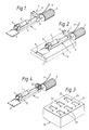
- the movable support 1 shown in Figures 1 and 2 comprises an elongate base 2 having at one end a rectangular tab 3 and, at the other end, a handle of thermally insulating material.
- first gripping means consisting of a spring clip 5 for holding a tubular connector body C and second gripping means 7 for holding an optical fibre F
- the second gripping means comprising a fixed jaw 8 and a second jaw constituted by a pivotally mounted lever 9.
- the lever 9 is acted on by spring-loaded plunger (not visible) mounted in the fixed jaw 8 and acting on the lever to the left (as seen in Figures 1 and 2) of the pivotal axis of the lever.
- the spring-loaded plunger biases the lever towards the fixed jaw 8, but if the lever is manually lifted against the bias, the plunger acts instead on the end face of the lever to hold the lever in the release position.
- the lever 9 may be released simply by flicking it with a finger.
- the elongate base 2 of the movable support 1 is positioned in a recess 11 in a flat surface of a first mounting 10 ( Figure 2), the walls of which recess prevent lateral and rotational movement of the movable support with respect to the first mounting while a tubular connector body C, whose bore contains epoxy resin or other heat-hardenable adhesive, is snapped into the spring clip 5.
- a tubular connector body C whose bore contains epoxy resin or other heat-hardenable adhesive
- an optical fibre F can be positioned in the bore of a tubular connector body C before the connector body is snapped into the spring clip 5.
- the movable support 1 is now removed from the first mounting 10, when the movable support is in the condition shown in Figure 1, and is inserted, in a vertically downwards direction, into a second mounting 20 ( Figure 3) which consists of a block 21 of metal or metal alloy with individual openings 22 for receiving a plurality of movable supports 1, each opening having along one boundary edge a slot 23 for receiving the tab 3 of a movable support. Because the tab 3 will enter the slot 23 before the protruding end of the optical fibre F mounted on the movable support 1 can enter the opening 22, risk of damage to the end of the optical fibre is substantially reduced.
- the metal block 21 is heated to a suitable temperature for hardening of the epoxy resin or other heat-hardenable adhesive inside the bore of the connector body C. After a suitable hardening period has elapsed, the movable support 1 is returned to the first mounting 10 to cool.
- the optical fibre F is now sufficiently firmly secured in the bore of the connector body C to eliminate risk of relative movement between the optical fibre and the connector body and to reduce substantially risk of breakage of the optical fibre during subsequent handling when cleaving and polishing of the protruding end of the optical fibre are effected. Cleaving of the optical fibre F is best done before the connector body C is removed from the movable support 1. If the connector body C is made in more than one part, if appropriate the parts may be assembled in the first gripping means 5 either before or after an optical fibre F is positioned on the movable support 1.
- Figure 4 shows a modified form of the preferred device in which the second gripping means 7 is constituted by a resilient gripping device in the form of a coil spring 37 having dimensions and spring characteristics such that an optical fibre F can be gripped simply by pressing it between turns of the spring.
Landscapes
- Physics & Mathematics (AREA)
- General Physics & Mathematics (AREA)
- Optics & Photonics (AREA)
- Mechanical Coupling Of Light Guides (AREA)
- Light Guides In General And Applications Therefor (AREA)
Applications Claiming Priority (4)
| Application Number | Priority Date | Filing Date | Title |
|---|---|---|---|
| GB8922782 | 1989-10-10 | ||
| GB898922782A GB8922782D0 (en) | 1989-10-10 | 1989-10-10 | Optical fibre termination |
| GB898922878A GB8922878D0 (en) | 1989-10-11 | 1989-10-11 | Optical fibre termination |
| GB8922878 | 1989-10-11 |
Publications (2)
| Publication Number | Publication Date |
|---|---|
| EP0422899A2 true EP0422899A2 (de) | 1991-04-17 |
| EP0422899A3 EP0422899A3 (en) | 1992-05-06 |
Family
ID=26296024
Family Applications (1)
| Application Number | Title | Priority Date | Filing Date |
|---|---|---|---|
| EP19900311057 Withdrawn EP0422899A3 (en) | 1989-10-10 | 1990-10-09 | Optical fibre termination |
Country Status (5)
| Country | Link |
|---|---|
| US (1) | US5120388A (de) |
| EP (1) | EP0422899A3 (de) |
| JP (1) | JPH03139604A (de) |
| AU (1) | AU630745B2 (de) |
| CA (1) | CA2027174A1 (de) |
Cited By (2)
| Publication number | Priority date | Publication date | Assignee | Title |
|---|---|---|---|---|
| EP0737876A3 (de) * | 1995-04-13 | 1997-06-04 | At & T Corp | Verfahren zur Herstellung eines faseroptischen Arrays und dessen Verwendung in einem Verbindungssystem zwischen einem faseroptischen Array und integriert-optischem Schaltkreis |
| CN112119237A (zh) * | 2018-07-31 | 2020-12-22 | 泰明顿服务责任有限公司 | 用于制造制动衬片的方法、用于缩短施加到用于制动衬片的衬片承载体上的粘合剂层的烘干时间的方法 |
Families Citing this family (6)
| Publication number | Priority date | Publication date | Assignee | Title |
|---|---|---|---|---|
| US5261020A (en) * | 1992-11-05 | 1993-11-09 | Siecor Corporation | Optical fiber connector assembly tool |
| US5348586A (en) * | 1993-10-29 | 1994-09-20 | Siecor Corporation | Ribbon prewet system |
| US5862289A (en) * | 1997-02-18 | 1999-01-19 | Amphenol Corporation | Adhesiveless fiber optic connector, and an apparatus and method for terminating a fiber optic cable to an adhesiveless fiber optic connector |
| TW566264U (en) * | 2001-11-28 | 2003-12-11 | Ind Tech Res Inst | Tool releasing mechanism used in vertical coupling type spindle of machine tool |
| US7149402B2 (en) * | 2004-11-15 | 2006-12-12 | 3M Innovative Properties Company | Device for holding field termination load adapter for optical connectors |
| US7466891B2 (en) * | 2006-06-13 | 2008-12-16 | Panduit Corp. | Activation tool for a fiber optic connector |
Family Cites Families (4)
| Publication number | Priority date | Publication date | Assignee | Title |
|---|---|---|---|---|
| GB1577729A (en) * | 1976-09-25 | 1980-10-29 | Plessey Co Ltd | Coupling of optic-waveguide elements |
| US4229402A (en) * | 1978-07-18 | 1980-10-21 | The United States Of America As Represented By The Secretary Of The Navy | Fiber optic connection method |
| DE3310973A1 (de) * | 1983-03-25 | 1984-09-27 | Siemens AG, 1000 Berlin und 8000 München | Steckerteil fuer loesbare steckverbindungen von lichtwellenleitern, verfahren zu dessen herstellung und vorrichtung zur ausfuehrung des verfahrens |
| SE8403740L (sv) * | 1984-07-17 | 1986-01-18 | Stratos Ab | Sett for fixering av en optisk fiber i ett kopplingselement samt ett pa settet framstellt kopplingselement |
-
1990
- 1990-10-04 US US07/592,860 patent/US5120388A/en not_active Expired - Fee Related
- 1990-10-09 AU AU63903/90A patent/AU630745B2/en not_active Ceased
- 1990-10-09 JP JP90269661A patent/JPH03139604A/ja active Pending
- 1990-10-09 CA CA002027174A patent/CA2027174A1/en not_active Abandoned
- 1990-10-09 EP EP19900311057 patent/EP0422899A3/en not_active Withdrawn
Cited By (4)
| Publication number | Priority date | Publication date | Assignee | Title |
|---|---|---|---|---|
| EP0737876A3 (de) * | 1995-04-13 | 1997-06-04 | At & T Corp | Verfahren zur Herstellung eines faseroptischen Arrays und dessen Verwendung in einem Verbindungssystem zwischen einem faseroptischen Array und integriert-optischem Schaltkreis |
| CN112119237A (zh) * | 2018-07-31 | 2020-12-22 | 泰明顿服务责任有限公司 | 用于制造制动衬片的方法、用于缩短施加到用于制动衬片的衬片承载体上的粘合剂层的烘干时间的方法 |
| KR20210021951A (ko) * | 2018-07-31 | 2021-03-02 | 티엠디 프릭션 서비스즈 게엠베하 | 브레이크 라이닝을 제조하기 위한 방법, 브레이크 라이닝을 위한 라이닝 캐리어에 적용된 접착제 층의 건조 시간을 감소시키기 위한 방법 |
| CN112119237B (zh) * | 2018-07-31 | 2022-04-08 | 泰明顿服务责任有限公司 | 用于制造制动衬片的方法、用于缩短衬片承载体上粘合剂层的烘干时间的方法 |
Also Published As
| Publication number | Publication date |
|---|---|
| EP0422899A3 (en) | 1992-05-06 |
| US5120388A (en) | 1992-06-09 |
| CA2027174A1 (en) | 1991-04-11 |
| JPH03139604A (ja) | 1991-06-13 |
| AU630745B2 (en) | 1992-11-05 |
| AU6390390A (en) | 1991-04-18 |
Similar Documents
| Publication | Publication Date | Title |
|---|---|---|
| US5120388A (en) | Optical fibre termination method and apparatus | |
| EP2984510A1 (de) | Kostengünstiger einwegglasfaserspalter und verfahren zum spalten einer optischen faser | |
| US5305406A (en) | Fiberoptic connector assembly and method and device for the manufacture thereof | |
| WO2001085401B1 (en) | Gripper and complementary handle for use with microcomponents | |
| US4461073A (en) | Device for inserting and extracting circuit modules with dual-in-line leads | |
| EP0387583B1 (de) | Schneidevorrichtung und -methode für optische Faser | |
| US3516142A (en) | Flat-pack manipulation tools | |
| US3797092A (en) | Dual in line package handling tool | |
| US5058280A (en) | Scroll saw blade holder | |
| US6643448B1 (en) | Optical fiber stripping tool | |
| EP0481339B1 (de) | Werkzeug zum vereinfachten Einbringen einer Glasfaser in ein Bauteil einer Verbindung | |
| GB2237125A (en) | Optical fibre termination by heat-hardening adhesive | |
| EP3518239A1 (de) | Verstellbarer träger für eine speichervorrichtung | |
| JPH06187872A (ja) | 感温スイッチ組立治具及び組立装置 | |
| EP1028334B1 (de) | Vorrichtung zur Wärmezufuhr an einen Kleber | |
| JP4256766B2 (ja) | 光ファイバの切断方法及びファイバカッター | |
| JPH0637493A (ja) | 電子部品挿入機 | |
| US4722135A (en) | Apparatus for placing surface mounting devices on a printer circuit board | |
| JPS62251705A (ja) | 2個の光フアイバ群の端部を対をなすように連結する装置 | |
| US20030086673A1 (en) | Method and apparatus for managing fiber optic cables | |
| US6170132B1 (en) | Magnetic laser bar clamp | |
| US5187767A (en) | Optical fiber prooftester and method for its use | |
| US4068363A (en) | Hand tool for manipulating coil springs | |
| JPH0740277A (ja) | ハンド | |
| CN214782122U (zh) | 一种带有标识的晶片夹具 |
Legal Events
| Date | Code | Title | Description |
|---|---|---|---|
| PUAI | Public reference made under article 153(3) epc to a published international application that has entered the european phase |
Free format text: ORIGINAL CODE: 0009012 |
|
| AK | Designated contracting states |
Kind code of ref document: A2 Designated state(s): AT BE CH DE DK ES FR GB GR IT LI LU NL SE |
|
| 17P | Request for examination filed |
Effective date: 19910424 |
|
| PUAL | Search report despatched |
Free format text: ORIGINAL CODE: 0009013 |
|
| AK | Designated contracting states |
Kind code of ref document: A3 Designated state(s): AT BE CH DE DK ES FR GB GR IT LI LU NL SE |
|
| 17Q | First examination report despatched |
Effective date: 19931216 |
|
| STAA | Information on the status of an ep patent application or granted ep patent |
Free format text: STATUS: THE APPLICATION IS DEEMED TO BE WITHDRAWN |
|
| 18D | Application deemed to be withdrawn |
Effective date: 19940427 |