EP0423018A1 - Einrichtung zur Transformation eines Bildanalysesignals in ein binäres Signal - Google Patents
Einrichtung zur Transformation eines Bildanalysesignals in ein binäres Signal Download PDFInfo
- Publication number
- EP0423018A1 EP0423018A1 EP90402805A EP90402805A EP0423018A1 EP 0423018 A1 EP0423018 A1 EP 0423018A1 EP 90402805 A EP90402805 A EP 90402805A EP 90402805 A EP90402805 A EP 90402805A EP 0423018 A1 EP0423018 A1 EP 0423018A1
- Authority
- EP
- European Patent Office
- Prior art keywords
- signal
- value
- image analysis
- boundary
- threshold
- Prior art date
- Legal status (The legal status is an assumption and is not a legal conclusion. Google has not performed a legal analysis and makes no representation as to the accuracy of the status listed.)
- Withdrawn
Links
- 230000001131 transforming effect Effects 0.000 title claims description 4
- 238000010191 image analysis Methods 0.000 claims description 33
- 238000004458 analytical method Methods 0.000 claims description 16
- 230000032683 aging Effects 0.000 description 3
- 238000010586 diagram Methods 0.000 description 3
- 230000009466 transformation Effects 0.000 description 3
- 238000001514 detection method Methods 0.000 description 2
- 230000010354 integration Effects 0.000 description 2
- 230000007423 decrease Effects 0.000 description 1
- 230000003111 delayed effect Effects 0.000 description 1
- 235000020281 long black Nutrition 0.000 description 1
Images

Classifications
-
- H—ELECTRICITY
- H04—ELECTRIC COMMUNICATION TECHNIQUE
- H04N—PICTORIAL COMMUNICATION, e.g. TELEVISION
- H04N1/00—Scanning, transmission or reproduction of documents or the like, e.g. facsimile transmission; Details thereof
- H04N1/40—Picture signal circuits
- H04N1/403—Discrimination between the two tones in the picture signal of a two-tone original
Definitions
- the present invention relates to a device for transforming an image analysis signal into a binary signal, comprising means for comparing the instantaneous value of said image analysis signal with the value of a signal threshold and first generation means for generating said threshold signal in response to the average value, over a first time interval, of said image analysis signal.
- Such a device is used in particular in fax machines.
- the image to be reproduced remotely or, where appropriate, locally is analyzed by a device which delivers an image analysis signal.
- This signal results from the detection of the light intensity reflected by the document carrying the image, lit by a lamp.
- the signal value is maximum for a white image point, and minimum for a black image point.
- the image is analyzed line by line, each line being analyzed point by point. Given the speed at which it is necessary to analyze the image, and the limited bandwidth of the analysis circuits, the image analysis signal is not a binary signal, even when the image analyzed only includes black dots or white dots.
- the level of white can vary considerably from one image to another, or even from one part to another of the same image, in particular according to the nature and the color of the support. It follows from these considerations that the image analysis signal has fluctuating characteristics.
- This transformation is carried out, in a known manner, by comparison of the image analysis signal with a black / white decision threshold.
- a fixed decision threshold independent of the analysis signal
- a threshold signal is generated in response to an average value of the image analysis signal, obtained from the values taken by this signal before its compared value . More precisely, the value of the threshold signal is calculated according to a formula implementing the average value of the white points and the average value of the black points, which requires the use of an auxiliary encoder to decide whether a point is White or black.
- the present invention aims to overcome these drawbacks.
- a device of the type defined above characterized in that it comprises second generation means for generating a boundary signal of constant or slowly variable value and intermediate between the two extreme values capable of 'be taken by said image analysis signal, and said first generation means are arranged so that the value of said threshold signal is between said average value over the first time interval of the image analysis signal and said value of the boundary signal.
- the threshold always remains distinct from the average value of the signal, and the long black, or white, areas are thus properly rendered. For example, for a black range, the average of the values taken by the signal is practically zero and therefore less than the value of the boundary signal. Then the threshold remains above this average, and it is decided that the point compared is black as long as the corresponding value of the image analysis signal remains practically zero. Thus, the black area is properly rendered. It would be the same for a white beach.
- the device is capable of reproducing suitably both black characters on a white background and white characters on a black background, and this in the same document.
- the average value of the analysis signal is very high, therefore in principle greater than the value of the boundary signal, and the threshold is established at a value between the average value and the value of the boundary signal, that is to say also relatively high, while remaining, however, always below the average value. Then, the chances of detecting a drop in signal level, therefore a black point, are high, since the threshold value is high.
- the average value of the analysis signal becomes very low, therefore less than the value of the boundary signal, and the threshold is established at a value between the average value and the value of the signal border, that is to say relatively weak, while remaining above the average value. Then the chances of detecting an increase in the signal level, therefore a white point, are high.
- said first generation means are arranged so that said threshold signal is equal to the average of a weighted sum of said image analysis signal and said boundary signal.
- Such an embodiment is particularly simple, and therefore safe and inexpensive.
- said weighted sum is the sum of said image analysis signal assigned with a first weighting coefficient and said boundary signal assigned with a second weighting coefficient, the sum of said first and second weighting coefficients is equal to l unit, and said first weighting coefficient is greater than said second weighting coefficient.
- the threshold signal relatively faithfully follows the variations in the average value of the image analysis signal, while remaining below this average value when the latter is high, and greater when it is low.
- said second generation means comprise first calculation means, for calculating a first value of said boundary signal in response to a control signal.
- the user of the device can choose the level of the border signal to adapt its value to the image or document to be analyzed, depending on whether the background is light or dark, for example. Such a choice was not provided for on the devices of the prior art.
- said second generation means comprise means for determining and storing the extreme value of said image analysis signal resulting from the analysis of a white area.
- said second generation means comprise second calculation means, for calculating a second value of said boundary signal in response to the average value, over a second time interval greater than said first time interval, of said analysis signal. image, and, where appropriate, means for selecting said first or said second value of the boundary signal.
- the value of the boundary signal is calculated automatically and varies throughout the document, which is preferable for certain types of documents, such as those with very light areas and very dark areas. In principle, it is then possible to select either this automatic operating mode or the "manual" operating mode where the level of the boundary signal is chosen by the user.
- the transformation device of the invention is intended to transform an image analysis signal V into a binary signal VB.
- the image analysis signal V is delivered by the document analysis device, not shown, of a fax machine. This is an analog signal whose amplitude varies within a range limited by two extreme values V n and V b .
- the value V n is here the minimum value, corresponding to black, and the value V b is the maximum value, corresponding to white. While the value V n is always the same, for example zero, the value V b may vary over time, depending on the aging of the document lighting tube or lamp, as already mentioned.
- the binary signal VB is intended to control the facsimile printing device if it is operating in local mode like a photocopier, or to be processed and then sent remotely if the facsimile is operating in normal mode.
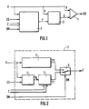
- the device of the invention comprises, with reference to FIG. 1, a comparator 1 provided with a first input receiving the signal V, with a second input receiving a threshold signal S and an output delivering the signal VB.
- a circuit 2 for generating the threshold signal S is provided with a first input receiving the signal V, a second input receiving a boundary signal F, and an output delivering the threshold signal S.
- a circuit 7 for generating the boundary signal F is provided with a first input receiving the signal V, a second input receiving a binary signal CE for calibration control, a third input receiving a digital signal C for controlling the value of the border signal F, of a fourth input receiving a binary signal SM for selection of operating mode, and of an output delivering the border signal F.
- Circuit 2 is arranged so that the threshold signal S is equal to the average of a weighted sum SP of the signal V and of the boundary signal F.
- the average of the sum SP which gives rise to the threshold signal S is carried out over a time interval corresponding to the m last image points analyzed before the image point whose intensity is compared in the comparator 1.
- the threshold signal S results from an analog integration of the weighted sum signal SP, of time constant equal to the analysis duration of m picture points.
- a + b 1 (3) that is, the sum of the two weighting coefficients a and b is equal to 1, so that the value of the weighted sum signal SP is always between the value of the signal V and that of the boundary signal F.
- the coefficient a which affects the signal V is greater than the coefficient b which affects the boundary signal F, that is: a> b (4)
- the value of the signal SP remains closer to the value of the signal V than to the value of the boundary signal F, which allows better detection of the variations of the signal V.
- circuit 2 The design of an analog electronic circuit which performs the function which has just been defined for circuit 2 is within the reach of the skilled person, and circuit 2 for generating the threshold signal will not be described further.
- the circuit 7 comprises a circuit 4 for determining and storing the extreme value V b , provided with a first input receiving the signal V, with a second input receiving the signal CE, and an output delivering a signal of value V b .
- the circuit 7 also includes a calculation circuit 3, provided with a first input connected to the output of the circuit 4 for determining and storing the value V b , with a second input receiving the digital signal C, and with a output delivering an F1 signal.
- the circuit 7 here also includes a calculation circuit 5, provided with an input receiving the signal V and an output delivering a signal F2, as well as a switch 6, for sending to the output of the circuit 7, ie the signal F1 , or the signal F2.
- the switch 6 is controllable, and its control input receives the binary signal SM for mode selection.
- the circuit 4 for determining and storing the value V b is arranged to calculate and store the value of the signal V applied to its first input while the signal CE applied to its second input is at the high level, for example.
- the facsimile machine is arranged to pass the CE signal to the high level just before the analysis of each of the documents, and a white strip is provided on the paper support which is then analyzed before the document itself.
- the circuit 4 comprises for example a comparator which, as soon as the signal CE goes high, compares to the signal V a variable auxiliary signal. As soon as the equality between signal V and the auxiliary signal is detected, the latter ceases to vary and its value is memorized and applied to the output of circuit 4. As the CE signal does not go high until the white range provided on the paper support is analyzed, the circuit 4 permanently presents on its output the value V b which corresponds to white.
- the calculation circuit 3 calculates the signal F1 in response to the control signal C, and to the constant level signal V b at the output of the circuit 4.
- circuit 3 includes a digital converter as output -analog.
- the control signal C results from a choice made by the user of the fax machine, choice made for example using the keyboard provided on the fax machine.
- the calculation circuit 5 calculates the signal F2 in response here to the average value of the signal V, carried out over a time interval corresponding to the p last points analyzed before the image point whose intensity is compared in the comparator 1.
- the number p is notably greater than the number m of image points on which the average of the weighted sum SP in circuit 2 is carried out.
- the number p is worth approximately 800, that is to say that it corresponds to half a line of image analysis. As in circuit 2, this average results from an analog integration of the signal V.
- the time constant is here equal to the duration of analysis of p points.
- the device which has just been described operates as follows.
- the value V b at the output of circuit 4 is updated before analysis of each document, account is automatically taken of the factors which can affect its level, such as the aging of the tube, for example, and the signal F1, this is that is to say here the boundary signal F, is adapted accordingly.
- the signal F is then of constant value throughout the analysis of the document.
- the signal threshold S shown in dotted lines follows the fluctuations of signal V with a certain delay.
- the threshold signal S never catches up with signal V but always remains lower or higher , depending on whether the signal V is established at a level higher or lower, respectively, than the border signal F.
- FIG. 3 shows stages of the signal V higher than the boundary signal F, and for which the threshold signal S is established, with a certain delay, at a value lower than that of the stage of the signal V. Then, variations in the instantaneous value of signal V, which reflect the presence of dark dots on a light background, will be very quickly detected by comparator 1.
- the stages of the signal V are lower than the boundary signal F, and the threshold signal S is established, with a certain delay, at a value greater than that of the stages of the signal V. Then, the variations of the instantaneous value which translate the presence of clear points on a dark background will be very quickly detected.
- the user can adapt the value of the signal F1 to the type of document analyzed by programming the control signal C accordingly.
- the user decreases the level of the signal F1, while to analyze a relatively clear document, it increases the level of the signal F1.
- the value of the border signal F is calculated automatically, and varies throughout the document. Circuit 5 calculates the signal F2 which meets these criteria. Also, the user, for such a document, selects the automatic mode by means of the signal SM and the signal F is then equal to the signal F2. In this case, the value of the boundary signal F is slowly variable.
- the present invention is not limited to the description which has just been made of a device in which the circuits perform analog processing, and it is within the capacity of a person skilled in the art to design a device in accordance with the invention in which the circuits carry out the processing operations which have been described, but numerically.
- the circuit 7 for generating the boundary signal does not include one or more of the circuits such as circuits 3, 4 and 5, if the functions of these circuits are judged useless for the application considered. , or if we want to reduce the cost of the device.
- the device of the invention is particularly useful for fax machines, it is obviously possible to use it in other types of apparatus.
Landscapes
- Engineering & Computer Science (AREA)
- Multimedia (AREA)
- Signal Processing (AREA)
- Facsimile Image Signal Circuits (AREA)
Applications Claiming Priority (2)
| Application Number | Priority Date | Filing Date | Title |
|---|---|---|---|
| FR8913143A FR2652971A1 (fr) | 1989-10-09 | 1989-10-09 | Dispositif de transformation d'un signal d'analyse d'image en un signal binaire. |
| FR8913143 | 1989-10-09 |
Publications (1)
| Publication Number | Publication Date |
|---|---|
| EP0423018A1 true EP0423018A1 (de) | 1991-04-17 |
Family
ID=9386200
Family Applications (1)
| Application Number | Title | Priority Date | Filing Date |
|---|---|---|---|
| EP90402805A Withdrawn EP0423018A1 (de) | 1989-10-09 | 1990-10-09 | Einrichtung zur Transformation eines Bildanalysesignals in ein binäres Signal |
Country Status (2)
| Country | Link |
|---|---|
| EP (1) | EP0423018A1 (de) |
| FR (1) | FR2652971A1 (de) |
Citations (3)
| Publication number | Priority date | Publication date | Assignee | Title |
|---|---|---|---|---|
| EP0089931A2 (de) * | 1982-03-22 | 1983-09-28 | Ing. C. Olivetti & C., S.p.A. | Apparat zur Abtastung und digitalen Verarbeitung von Halbtonbildern |
| DE3433493A1 (de) * | 1983-09-12 | 1985-04-04 | Ricoh Co., Ltd., Tokio/Tokyo | System zur digitalisierung von bildsignalen |
| EP0150001A2 (de) * | 1984-01-24 | 1985-07-31 | Fuji Photo Film Co., Ltd. | Binärdatenumsetzungsverfahren |
-
1989
- 1989-10-09 FR FR8913143A patent/FR2652971A1/fr not_active Withdrawn
-
1990
- 1990-10-09 EP EP90402805A patent/EP0423018A1/de not_active Withdrawn
Patent Citations (3)
| Publication number | Priority date | Publication date | Assignee | Title |
|---|---|---|---|---|
| EP0089931A2 (de) * | 1982-03-22 | 1983-09-28 | Ing. C. Olivetti & C., S.p.A. | Apparat zur Abtastung und digitalen Verarbeitung von Halbtonbildern |
| DE3433493A1 (de) * | 1983-09-12 | 1985-04-04 | Ricoh Co., Ltd., Tokio/Tokyo | System zur digitalisierung von bildsignalen |
| EP0150001A2 (de) * | 1984-01-24 | 1985-07-31 | Fuji Photo Film Co., Ltd. | Binärdatenumsetzungsverfahren |
Also Published As
| Publication number | Publication date |
|---|---|
| FR2652971A1 (fr) | 1991-04-12 |
Similar Documents
| Publication | Publication Date | Title |
|---|---|---|
| CA1126852A (fr) | Dispositif de traitement d'un signal d'analyse d'image | |
| EP0048661B1 (de) | Demodulator eines frequenzmodulierten Signals | |
| FR2814028A1 (fr) | Appareil de capture d'images a scintillement reduit et procede d'ajustement automatique de niveau pour celui-ci | |
| EP0476302B1 (de) | Verfahren und Vorrichtung zur automatischen Steuerung der Verstärkung eines Verstärkers und die Verwendung dieses Verfahrens und dieser Vorrichtung bei der Verstärkungssteuerung eines Tuners, insbesondere eines Tuners für ein Videokommunikationsnetz | |
| EP0757452A1 (de) | Nachrichtenübertragungssystem durch elektrische Versorgungsleitungen | |
| FR2468150A1 (fr) | Systeme automatique de commande de la polarisation de l'electrode de developpement et du reperage du papier de tirage dans un copieur electrophotographique | |
| FR2731123A1 (fr) | Correction de gain de haut-parleur pour un terminal telephonique mains-libres | |
| FR2652697A1 (fr) | Extracteur de donnees numeriques dans un signal video. | |
| EP0376866B1 (de) | Steueranordnung für Freisprechtelefonapparat in Halbduplexbetrieb | |
| FR2516323A1 (fr) | Circuit servant a convertir un signal d'information en un signal rectangulaire | |
| EP0375038A1 (de) | Videobildwiedergabevorrichtung mit einer Kontrastregeleinheit und Verfahren zur Kontrasteinstellung einer solchen Wiedergabevorrichtung | |
| FR2508265A1 (fr) | Circuit de desaccentuation video | |
| FR2652971A1 (fr) | Dispositif de transformation d'un signal d'analyse d'image en un signal binaire. | |
| EP1351498A2 (de) | Echtzeitverarbeitungsmethode eines Bildsignales | |
| EP0419341B1 (de) | Videoempfangsausrüstung | |
| FR2487613A1 (fr) | Dispositif de lecture ou de restitution d'un document, en particulier pour appareil de telecopie | |
| FR2555664A1 (fr) | Dispositif pour detecter des combustions accompagnees de cliquetis dans des moteurs a combustion interne | |
| FR2650143A1 (fr) | Circuit de correction automatique de l'equilibre des couleurs | |
| CA1173555A (fr) | Procede et dispositif d'accentuation des traits d'une image | |
| EP0193469A2 (de) | Verfahren und Einrichtung zur Steuerung eines Freisprechapparates mit Wechselsprechbetrieb | |
| EP0848547B1 (de) | Schnittstellenschaltung für Videokamera | |
| FR2656485A1 (fr) | Procede de regulation d'une camera a couplage de charge, et camera pour sa mise en óoeuvre. | |
| FR2512969A1 (fr) | Dispositif de commutation pour elements photosensibles de mise au point pour appareil photographique | |
| KR960012549B1 (ko) | 팩시밀리(Facsimile)의 화상처리장치 | |
| EP0156725A1 (de) | Optischer Abtaster für Fernsehschirm- und Strichkodenabtastung |
Legal Events
| Date | Code | Title | Description |
|---|---|---|---|
| PUAI | Public reference made under article 153(3) epc to a published international application that has entered the european phase |
Free format text: ORIGINAL CODE: 0009012 |
|
| AK | Designated contracting states |
Kind code of ref document: A1 Designated state(s): AT BE CH DE DK ES FR GB GR IT LI LU NL SE |
|
| 17P | Request for examination filed |
Effective date: 19911016 |
|
| STAA | Information on the status of an ep patent application or granted ep patent |
Free format text: STATUS: THE APPLICATION IS DEEMED TO BE WITHDRAWN |
|
| 18D | Application deemed to be withdrawn |
Effective date: 19940503 |