EP0423029A1 - Vorrichtung und Verfahren zum Aufheben und Bewegen von Objekten - Google Patents
Vorrichtung und Verfahren zum Aufheben und Bewegen von Objekten Download PDFInfo
- Publication number
- EP0423029A1 EP0423029A1 EP90402827A EP90402827A EP0423029A1 EP 0423029 A1 EP0423029 A1 EP 0423029A1 EP 90402827 A EP90402827 A EP 90402827A EP 90402827 A EP90402827 A EP 90402827A EP 0423029 A1 EP0423029 A1 EP 0423029A1
- Authority
- EP
- European Patent Office
- Prior art keywords
- cylinder
- supports
- objects
- deck
- lifting
- Prior art date
- Legal status (The legal status is an assumption and is not a legal conclusion. Google has not performed a legal analysis and makes no representation as to the accuracy of the status listed.)
- Granted
Links
- 238000000034 method Methods 0.000 title claims description 15
- 230000000284 resting effect Effects 0.000 claims abstract description 6
- 238000006073 displacement reaction Methods 0.000 claims description 8
- 238000010276 construction Methods 0.000 claims description 4
- 239000000463 material Substances 0.000 claims description 3
- 238000007796 conventional method Methods 0.000 description 4
- 229920001343 polytetrafluoroethylene Polymers 0.000 description 3
- 239000004810 polytetrafluoroethylene Substances 0.000 description 3
- 240000008042 Zea mays Species 0.000 description 2
- 238000005452 bending Methods 0.000 description 2
- 229910000831 Steel Inorganic materials 0.000 description 1
- 238000006243 chemical reaction Methods 0.000 description 1
- 230000007547 defect Effects 0.000 description 1
- 230000000694 effects Effects 0.000 description 1
- 229940082150 encore Drugs 0.000 description 1
- 238000012986 modification Methods 0.000 description 1
- 230000004048 modification Effects 0.000 description 1
- 239000004570 mortar (masonry) Substances 0.000 description 1
- 229920001084 poly(chloroprene) Polymers 0.000 description 1
- -1 polytetrafluoroethylene Polymers 0.000 description 1
- 230000000630 rising effect Effects 0.000 description 1
- 239000010959 steel Substances 0.000 description 1
Images



Classifications
-
- E—FIXED CONSTRUCTIONS
- E01—CONSTRUCTION OF ROADS, RAILWAYS, OR BRIDGES
- E01D—CONSTRUCTION OF BRIDGES, ELEVATED ROADWAYS OR VIADUCTS; ASSEMBLY OF BRIDGES
- E01D19/00—Structural or constructional details of bridges
- E01D19/04—Bearings; Hinges
- E01D19/048—Bearings being adjustable once installed; Bearings used in incremental launching
-
- B—PERFORMING OPERATIONS; TRANSPORTING
- B66—HOISTING; LIFTING; HAULING
- B66F—HOISTING, LIFTING, HAULING OR PUSHING, NOT OTHERWISE PROVIDED FOR, e.g. DEVICES WHICH APPLY A LIFTING OR PUSHING FORCE DIRECTLY TO THE SURFACE OF A LOAD
- B66F1/00—Devices, e.g. jacks, for lifting loads in predetermined steps
- B66F1/02—Devices, e.g. jacks, for lifting loads in predetermined steps with locking elements, e.g. washers, co-operating with posts
- B66F1/025—Devices, e.g. jacks, for lifting loads in predetermined steps with locking elements, e.g. washers, co-operating with posts the devices being operated by fluid pressure
-
- E—FIXED CONSTRUCTIONS
- E01—CONSTRUCTION OF ROADS, RAILWAYS, OR BRIDGES
- E01D—CONSTRUCTION OF BRIDGES, ELEVATED ROADWAYS OR VIADUCTS; ASSEMBLY OF BRIDGES
- E01D21/00—Methods or apparatus specially adapted for erecting or assembling bridges
- E01D21/06—Methods or apparatus specially adapted for erecting or assembling bridges by translational movement of the bridge or bridge sections
- E01D21/065—Incremental launching
Definitions
- the present invention relates to a device for lifting and moving objects.
- the invention relates in particular to a device for building a bridge according to the method known as "pushed bridges", in which the objects to be lifted and to be moved are elements of the deck of said bridge.
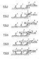
- FIGS 1 to 6 attached illustrate the conventional method of construction by pushing bridges.
- the reference 1 designates piles of bridges which are pre-installed.
- a first concrete deck element 2 is poured in front of the concrete abutment 3 which must connect the bridge to the ground 4 (see Figure 1).
- a second element 5 is cast behind the first element 2 (see FIG. 3).
- a fourth step the two elements 2 and 5 are pushed together towards the stacks 1 by a force F2 (FIG. 4).
- a third element 6 is then poured (see FIG. 5) and the three elements 2, 5 and 6 are pushed together on the stacks 1 (FIG. 6).
- the weight of a pushed deck can reach 30,000 tonnes in the final phase (approximate maximum value achieved to date).
- the coefficient of friction commonly varies between 1% and 5% in the case of a sliding surface made of PTFE (polytetrafluoroethylene).
- Longitudinal slopes can reach 3.5% in the case of works for TGV (high speed trains) and they can be higher than this value for road works. It can therefore be seen that the pushing forces can reach values greater than 30,000 ⁇ (0.035 + 0.05), or 2,550 tonnes.
- the bearing surface of the device on the stack is either horizontal or parallel to the deck.
- the conventional technique also has the defect of not ensuring the safety of the apron if the movement of the latter escapes the control of the operator, in the event for example of failure of the lifting and displacement means used.
- German patent application 1 905 997 describes a device for moving heavy loads on a horizontal surface by means of a lifting cylinder and a pushing cylinder.
- the object of the present invention is to remedy the drawbacks of known devices.
- the invention thus relates to a device for lifting and moving objects, comprising means for lifting objects resting on one or more temporary fixed supports and means for moving these objects to make them undergo translation relative to this or these supports, said means cooperating with a sliding surface located near said temporary support (s).
- this device is characterized in that said surface forms with the contact surface between the object to be moved and the support (s), a dihedral whose edge is directed opposite to the direction in which wishes to move the object, said surface being on a downward slope relative to the direction of movement of the object, said means being adapted to simultaneously lift and push the objects in order to maintain them during their movement at a predetermined distance from the - above the support (s).
- the means for moving these objects raise them and move over a surface forming a downward slope.
- the value of the slope along which the means of lifting objects move can be decided by the company. The more this slope is downward relative to the surface of displacement of the objects, the more the effort of pushing or displacement of the objects is reduced.
- the lifting and moving means are actuated simultaneously, despite the above-mentioned dihedral, the displaced objects can be kept at a predetermined distance above the support (s).
- the objects to be lifted and moved are elements of the deck of said bridge, the supports being arranged on piers of this bridge intended to support the deck elements.
- said means for lifting and moving the deck elements comprise a lower plate fixed on a surface formed on a bridge pier, an upper plate slidably mounted on the fixed lower plate, a first jack fixed perpendicular to the movable upper plate and whose movable head is adapted to come into contact with the deck element resting on one or more supports to lift it, at least one second jack having one of its fixed ends and its another end secured to the movable plate to move the latter relative to the fixed plate.
- the device designated by the reference 10 in Figure 7 is placed in a cavity 11 formed at the top of certain piers 1 of the bridge to be built. Certain batteries 1 thus receive such a device 10.
- the upper part of the stack 1 comprises, in the example shown, two supports 12, 13 on which the deck member 14 which is to be moved rests.
- This bearing surface is here located on a rising slope.
- the surface S along which the device 10 is capable of moving forms with the contact surface S1, S2 between the apron element 14 to be moved and the supports 12, 13 a dihedral whose edge (not visible in FIG. 7) is directed opposite the direction D in which it is desired to move the element 14.
- this surface S is on a downward slope relative to the direction of displacement D of element 14, so that it is inverse to the slope on which element 14 must move.
- the device 10 shown in Figures 7, 8A and 8B comprises a lower plate 15 fixed by a layer of mortar 17 on the inclined bottom 16 of the cavity 11 between two supports 12, 13. On this fixed plate 15 is mounted so sliding top plate 18.
- a first cylinder 19 is fixed perpendicularly to the movable upper plate 18 and whose movable head 20 is adapted to come into contact with the deck element 14 resting on the two supports 12, 13 to lift it. Stops 29 are provided on the movable plate 18 to prevent any sliding of the jack 19.
- One 21a, 22a of the ends of the jacks 21, 22 is fixed to the fixed plate 15 and the other ends 21b, 22b are integral with the movable plate 18.
- the jacks 21, 22 are thus designed to move the movable plate 18 relative to the fixed plate 15, along the surface S, between the two positions shown in Figures 8A and 8B.
- a layer 23 of material with a low coefficient of friction such as PTFE is interposed between the two plates 15 and 18.
- the head 20 of the first jack 10 has a striated surface 24 parallel to the contact surface S1, S2 between the deck member 14 and the two supports 12, 13. These ridges 24 allow d '' avoid any risk of sliding of the apron element 14.
- This striated surface can be replaced by a layer of neoprene or other anti-slip surface.
- the device 10 includes manometers 25, 26 for controlling the operating pressure of each of the jacks, as well as sensors 27, 28 for measuring the displacements of the bulkhead element 14 , order the jacks 19, 21 and to perfectly control their vertical and longitudinal movements.
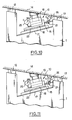
- the device 10 In the position shown in FIG. 9, the device 10 is at rest, the jacks 19 and 21 are all retracted, the pressure gauges 25, 26 display zero pressure, and the apron element 14 rests on the supports 12, 13: it cannot therefore move in one direction or the other.
- a first step (see FIG. 10), the operation of the lifting cylinder 19 is controlled until it develops approximately 90% of the force necessary to lift the deck element 14.
- the hydraulic circuit of the push cylinder 21 could include a non-return valve.
- the lifting cylinder 19 is mounted under pressure until it develops the necessary force (see position 100% of the pressure gauge 25), to lift the bulkhead element 14.
- the stroke of the lifting cylinder 19 is stopped as soon as the bulkhead element 14 has risen a few millimeters above the supports (12, 13).
- the pushing cylinder 21 is mounted in pressure until developing the force necessary for pushing (see FIG. 13; position 2 of the pressure gauge 26).
- a sensor 27 determines the position in altitude of the element 14 and thus controls the supply of the jack 19.
- the push cylinder 21 can thus move the apron element 14 along its maximum stroke, for example equal to 30 cm.
- the pressure in the pushing cylinder 21 is then reduced to 0. The same is done for the lifting cylinder 19.
- the strokes of the two cylinders 19 and 21 are also reduced to 0.
- the device 10 has thus returned to its initial position shown in FIG. 9. It is then ready for a new lifting and pushing cycle.
- the pushing force being reduced it may be possible to reduce the number of supports to be fitted with the device.
- the device according to the invention can be equipped with two control members: - a vertical steering device which will avoid bending the deck excessively at any time, keeping it at the chosen altitude. If the apron advances too quickly in the direction of pushing, it will deposit itself on its rest supports. If the apron begins to "move back" it will be raised by the wedge effect and the piloting of the lifting cylinder will cause a reduction in its pressure which will maintain it at the desired level and will avoid bending the apron by uneven support.
- a longitudinal control member which can also instantly deactivate the lifting cylinder (for example by preventing the movable plate from moving back 1 cm if the lifting cylinder is loaded).
- the device according to the invention can be used to lift and move objects other than bridge deck elements.
- the movement of objects can be carried out horizontally or along a downward slope, the main thing being that the sliding surface of the lifting and pushing means takes place along a slope different from that of the objects to be moved.
- the invention can also be applied to the pushing of bridges made of steel deck elements or other material.
Landscapes
- Engineering & Computer Science (AREA)
- Structural Engineering (AREA)
- Architecture (AREA)
- Civil Engineering (AREA)
- Mechanical Engineering (AREA)
- Life Sciences & Earth Sciences (AREA)
- Fluid Mechanics (AREA)
- Geology (AREA)
- Physics & Mathematics (AREA)
- Bridges Or Land Bridges (AREA)
- Warehouses Or Storage Devices (AREA)
- Carriers, Traveling Bodies, And Overhead Traveling Cranes (AREA)
- Control And Safety Of Cranes (AREA)
- Forklifts And Lifting Vehicles (AREA)
Priority Applications (1)
| Application Number | Priority Date | Filing Date | Title |
|---|---|---|---|
| AT90402827T ATE87684T1 (de) | 1989-10-11 | 1990-10-10 | Vorrichtung und verfahren zum aufheben und bewegen von objekten. |
Applications Claiming Priority (2)
| Application Number | Priority Date | Filing Date | Title |
|---|---|---|---|
| FR8913269A FR2652836B1 (fr) | 1989-10-11 | 1989-10-11 | Dispositif pour soulever et deplacer des objets et procede pour sa mise en óoeuvre. |
| FR8913269 | 1989-10-11 |
Publications (2)
| Publication Number | Publication Date |
|---|---|
| EP0423029A1 true EP0423029A1 (de) | 1991-04-17 |
| EP0423029B1 EP0423029B1 (de) | 1993-03-31 |
Family
ID=9386279
Family Applications (1)
| Application Number | Title | Priority Date | Filing Date |
|---|---|---|---|
| EP90402827A Expired - Lifetime EP0423029B1 (de) | 1989-10-11 | 1990-10-10 | Vorrichtung und Verfahren zum Aufheben und Bewegen von Objekten |
Country Status (4)
| Country | Link |
|---|---|
| EP (1) | EP0423029B1 (de) |
| AT (1) | ATE87684T1 (de) |
| DE (1) | DE69001231T2 (de) |
| FR (1) | FR2652836B1 (de) |
Cited By (4)
| Publication number | Priority date | Publication date | Assignee | Title |
|---|---|---|---|---|
| US5566414A (en) * | 1993-10-20 | 1996-10-22 | Matsuo Engineering Co., Ltd. | Bridge raising/supporting method and bearing device for the method |
| US5920938A (en) * | 1997-08-05 | 1999-07-13 | Elcock; Stanley E. | Method for rejuvenating bridge hinges |
| FR2969993A1 (fr) * | 2010-12-30 | 2012-07-06 | Edouard Andre Georges Duminil | Patin modulable |
| IT201700053686A1 (it) * | 2017-05-18 | 2018-11-18 | Cimolai S P A | Macchina e procedimento per il varo di una struttura orizzontale, come l'impalcato di un ponte, un viadotto, un cavalcavia, o simili manufatti |
Families Citing this family (2)
| Publication number | Priority date | Publication date | Assignee | Title |
|---|---|---|---|---|
| CN110158472B (zh) * | 2019-04-28 | 2021-12-21 | 中交第二航务工程局有限公司 | 一种模块化多功能步履式顶推设备 |
| CN115961560B (zh) * | 2022-12-23 | 2026-04-17 | 武汉科技大学 | 桥梁顶推施工滑块 |
Citations (4)
| Publication number | Priority date | Publication date | Assignee | Title |
|---|---|---|---|---|
| DE1905997A1 (de) * | 1969-02-07 | 1970-08-20 | Eberspaecher Emil | Hydraulik-Verschiebeeinrichtung fuer schwere Lasten |
| US3570207A (en) * | 1969-07-10 | 1971-03-16 | Pierre Launay | Method of advancing bridging structures made from prestressed concrete |
| GB1548897A (en) * | 1976-05-06 | 1979-07-18 | Redpath Dorman Long Ltd | Movement of bridge spans or the like |
| FR2616459A1 (fr) * | 1987-06-15 | 1988-12-16 | Bouygues Sa | Procede et dispositif pour deplacer un pont ou autre ouvrage, par poussage, afin de le mettre en place sur des supports |
Family Cites Families (1)
| Publication number | Priority date | Publication date | Assignee | Title |
|---|---|---|---|---|
| US1548897A (en) * | 1924-01-07 | 1925-08-11 | Lewis Invisible Stitch Machine | Quick-adjusting plunger mechanism for blindstitch sewing machines |
-
1989
- 1989-10-11 FR FR8913269A patent/FR2652836B1/fr not_active Expired - Lifetime
-
1990
- 1990-10-10 DE DE9090402827T patent/DE69001231T2/de not_active Expired - Fee Related
- 1990-10-10 EP EP90402827A patent/EP0423029B1/de not_active Expired - Lifetime
- 1990-10-10 AT AT90402827T patent/ATE87684T1/de active
Patent Citations (4)
| Publication number | Priority date | Publication date | Assignee | Title |
|---|---|---|---|---|
| DE1905997A1 (de) * | 1969-02-07 | 1970-08-20 | Eberspaecher Emil | Hydraulik-Verschiebeeinrichtung fuer schwere Lasten |
| US3570207A (en) * | 1969-07-10 | 1971-03-16 | Pierre Launay | Method of advancing bridging structures made from prestressed concrete |
| GB1548897A (en) * | 1976-05-06 | 1979-07-18 | Redpath Dorman Long Ltd | Movement of bridge spans or the like |
| FR2616459A1 (fr) * | 1987-06-15 | 1988-12-16 | Bouygues Sa | Procede et dispositif pour deplacer un pont ou autre ouvrage, par poussage, afin de le mettre en place sur des supports |
Non-Patent Citations (1)
| Title |
|---|
| CIVIL ENGINEERING, vol. 47, no. 3, mars 1977, pages 60-63; W. BAUR: "Bridge erection by launching is fast, safe, and efficient" * |
Cited By (4)
| Publication number | Priority date | Publication date | Assignee | Title |
|---|---|---|---|---|
| US5566414A (en) * | 1993-10-20 | 1996-10-22 | Matsuo Engineering Co., Ltd. | Bridge raising/supporting method and bearing device for the method |
| US5920938A (en) * | 1997-08-05 | 1999-07-13 | Elcock; Stanley E. | Method for rejuvenating bridge hinges |
| FR2969993A1 (fr) * | 2010-12-30 | 2012-07-06 | Edouard Andre Georges Duminil | Patin modulable |
| IT201700053686A1 (it) * | 2017-05-18 | 2018-11-18 | Cimolai S P A | Macchina e procedimento per il varo di una struttura orizzontale, come l'impalcato di un ponte, un viadotto, un cavalcavia, o simili manufatti |
Also Published As
| Publication number | Publication date |
|---|---|
| DE69001231T2 (de) | 1993-09-02 |
| FR2652836A1 (fr) | 1991-04-12 |
| EP0423029B1 (de) | 1993-03-31 |
| ATE87684T1 (de) | 1993-04-15 |
| DE69001231D1 (de) | 1993-05-06 |
| FR2652836B1 (fr) | 1992-12-18 |
Similar Documents
| Publication | Publication Date | Title |
|---|---|---|
| EP0964102B1 (de) | Vorrichtung zum Transport und zur Installation des Decks einer Ölplatform im Meer | |
| EP0379448B1 (de) | Kran mit anhebbarem Ausleger und mit einer Ausleger-Rückstossvorrichtung | |
| EP1773707B1 (de) | Hebeanordnung | |
| FR2853304A1 (fr) | Dispositif pour deplacer une charge lourde | |
| FR2691187A1 (fr) | Procédé pour commander automatiquement le moteur d'orientation d'une excavatrice. | |
| EP3415458B1 (de) | Gerät und verfahren zur automatischen spannung eines verteilerkabels eines kranes | |
| WO1998009898A1 (fr) | Dispositif de distribution de palettes | |
| EP0423029B1 (de) | Vorrichtung und Verfahren zum Aufheben und Bewegen von Objekten | |
| CA3002784A1 (fr) | Systeme et methode de manutention pour faciliter la maintenance d'une unite de couchage, en particulier un lit medicalise | |
| EP0649686A1 (de) | Walzwerk mit axial verschiebaren Walzen | |
| EP0827935B1 (de) | Verfahren zum Steuern des Betriebs einer Lastkompensationsvorrichtung und Lastkompensationsvorrichtung zur Durchführung dieses Verfahrens | |
| FR2615500A1 (fr) | Dispositif compensateur de charge pour un engin de manutention et procede pour la mise en oeuvre d'une telle compensation | |
| FR2802504A1 (fr) | Dispositif ameliore d'equilibrage d'un navire notamment en roulis | |
| BE1022016B1 (fr) | Dispositif elevateur | |
| EP3141517B1 (de) | Schnellmontage-kran ohne ballastierung | |
| EP2109575B1 (de) | Vorrichtung zur lagerung von objekten auf einer mobilen palette | |
| EP1186568B1 (de) | Hubarbeitsbühne und Verfahren zum Steuern einer sich darauf befindenden Last | |
| FR2624840A1 (fr) | Dispositif ralentisseur de securite pour la cabine d'un ascenseur ou d'un monte-charge | |
| FR2467169A1 (fr) | Grue a tour | |
| FR2543123A1 (fr) | Procede et dispositif pour faire avancer un cable pendant, dont les cables d'extraction sont bloques dans des installations d'extraction de puits a poulie motrice, a cable unique ou multiple | |
| FR2586667A1 (fr) | Monte-charge autoporte a bras telescopiques jumeles | |
| FR2645521A1 (fr) | Plate-forme elevatrice mobile constituant un support pour une camera | |
| EP1775252B1 (de) | Verfahren und Vorrichtung zur Steuerung der Last eines Drehkranes mit ausklappbarem Ausleger | |
| EP2364262B1 (de) | Gerät zur verschiebung einer bohrinsel und eren aufbau auf einer schwimmenden oder festen unterstruktur | |
| FR2877656A1 (fr) | Systeme de plate-forme elevatrice |
Legal Events
| Date | Code | Title | Description |
|---|---|---|---|
| PUAI | Public reference made under article 153(3) epc to a published international application that has entered the european phase |
Free format text: ORIGINAL CODE: 0009012 |
|
| 17P | Request for examination filed |
Effective date: 19901015 |
|
| AK | Designated contracting states |
Kind code of ref document: A1 Designated state(s): AT BE CH DE DK ES FR GB GR IT LI LU NL SE |
|
| 17Q | First examination report despatched |
Effective date: 19920207 |
|
| GRAA | (expected) grant |
Free format text: ORIGINAL CODE: 0009210 |
|
| AK | Designated contracting states |
Kind code of ref document: B1 Designated state(s): AT BE CH DE DK ES FR GB GR IT LI LU NL SE |
|
| PG25 | Lapsed in a contracting state [announced via postgrant information from national office to epo] |
Ref country code: IT Free format text: LAPSE BECAUSE OF FAILURE TO SUBMIT A TRANSLATION OF THE DESCRIPTION OR TO PAY THE FEE WITHIN THE PRE;WARNING: LAPSES OF ITALIAN PATENTS WITH EFFECTIVE DATE BEFORE 2007 MAY HAVE OCCURRED AT ANY TIME BEFORE 2007. THE CORRECT EFFECTIVE DATE MAY BE DIFFERENT FROM THE ONE RECORDED.SCRIBED TIME-LIMIT Effective date: 19930331 Ref country code: GR Free format text: LAPSE BECAUSE OF FAILURE TO SUBMIT A TRANSLATION OF THE DESCRIPTION OR TO PAY THE FEE WITHIN THE PRESCRIBED TIME-LIMIT Effective date: 19930331 Ref country code: GB Effective date: 19930331 Ref country code: NL Effective date: 19930331 Ref country code: ES Free format text: THE PATENT HAS BEEN ANNULLED BY A DECISION OF A NATIONAL AUTHORITY Effective date: 19930331 Ref country code: DK Effective date: 19930331 Ref country code: SE Effective date: 19930331 |
|
| REF | Corresponds to: |
Ref document number: 87684 Country of ref document: AT Date of ref document: 19930415 Kind code of ref document: T |
|
| REF | Corresponds to: |
Ref document number: 69001231 Country of ref document: DE Date of ref document: 19930506 |
|
| NLV1 | Nl: lapsed or annulled due to failure to fulfill the requirements of art. 29p and 29m of the patents act | ||
| GBV | Gb: ep patent (uk) treated as always having been void in accordance with gb section 77(7)/1977 [no translation filed] |
Effective date: 19930331 |
|
| PG25 | Lapsed in a contracting state [announced via postgrant information from national office to epo] |
Ref country code: LU Free format text: LAPSE BECAUSE OF NON-PAYMENT OF DUE FEES Effective date: 19931031 Ref country code: BE Effective date: 19931031 |
|
| PLBE | No opposition filed within time limit |
Free format text: ORIGINAL CODE: 0009261 |
|
| STAA | Information on the status of an ep patent application or granted ep patent |
Free format text: STATUS: NO OPPOSITION FILED WITHIN TIME LIMIT |
|
| 26N | No opposition filed | ||
| BERE | Be: lapsed |
Owner name: SPIE-BATIGNOLLES Effective date: 19931031 |
|
| REG | Reference to a national code |
Ref country code: CH Ref legal event code: NV Representative=s name: BOVARD AG PATENTANWAELTE |
|
| PGFP | Annual fee paid to national office [announced via postgrant information from national office to epo] |
Ref country code: AT Payment date: 19990909 Year of fee payment: 10 |
|
| PGFP | Annual fee paid to national office [announced via postgrant information from national office to epo] |
Ref country code: CH Payment date: 19991021 Year of fee payment: 10 |
|
| PGFP | Annual fee paid to national office [announced via postgrant information from national office to epo] |
Ref country code: DE Payment date: 19991228 Year of fee payment: 10 |
|
| PG25 | Lapsed in a contracting state [announced via postgrant information from national office to epo] |
Ref country code: AT Free format text: LAPSE BECAUSE OF NON-PAYMENT OF DUE FEES Effective date: 20001010 |
|
| PGFP | Annual fee paid to national office [announced via postgrant information from national office to epo] |
Ref country code: FR Payment date: 20001013 Year of fee payment: 11 |
|
| PG25 | Lapsed in a contracting state [announced via postgrant information from national office to epo] |
Ref country code: LI Free format text: LAPSE BECAUSE OF NON-PAYMENT OF DUE FEES Effective date: 20001031 Ref country code: CH Free format text: LAPSE BECAUSE OF NON-PAYMENT OF DUE FEES Effective date: 20001031 |
|
| REG | Reference to a national code |
Ref country code: CH Ref legal event code: PL |
|
| PG25 | Lapsed in a contracting state [announced via postgrant information from national office to epo] |
Ref country code: DE Free format text: LAPSE BECAUSE OF NON-PAYMENT OF DUE FEES Effective date: 20010703 |
|
| PG25 | Lapsed in a contracting state [announced via postgrant information from national office to epo] |
Ref country code: FR Free format text: LAPSE BECAUSE OF NON-PAYMENT OF DUE FEES Effective date: 20020628 |
|
| REG | Reference to a national code |
Ref country code: FR Ref legal event code: ST |