EP0423051A2 - Seitendrucker in dem Plottergraphiken in einen Text eingefügt werden - Google Patents
Seitendrucker in dem Plottergraphiken in einen Text eingefügt werden Download PDFInfo
- Publication number
- EP0423051A2 EP0423051A2 EP90480102A EP90480102A EP0423051A2 EP 0423051 A2 EP0423051 A2 EP 0423051A2 EP 90480102 A EP90480102 A EP 90480102A EP 90480102 A EP90480102 A EP 90480102A EP 0423051 A2 EP0423051 A2 EP 0423051A2
- Authority
- EP
- European Patent Office
- Prior art keywords
- commands
- page
- printer
- data
- plotter
- Prior art date
- Legal status (The legal status is an assumption and is not a legal conclusion. Google has not performed a legal analysis and makes no representation as to the accuracy of the status listed.)
- Granted
Links
Images




Classifications
-
- G—PHYSICS
- G06—COMPUTING OR CALCULATING; COUNTING
- G06K—GRAPHICAL DATA READING; PRESENTATION OF DATA; RECORD CARRIERS; HANDLING RECORD CARRIERS
- G06K15/00—Arrangements for producing a permanent visual presentation of the output data, e.g. computer output printers
- G06K15/02—Arrangements for producing a permanent visual presentation of the output data, e.g. computer output printers using printers
-
- G—PHYSICS
- G06—COMPUTING OR CALCULATING; COUNTING
- G06K—GRAPHICAL DATA READING; PRESENTATION OF DATA; RECORD CARRIERS; HANDLING RECORD CARRIERS
- G06K15/00—Arrangements for producing a permanent visual presentation of the output data, e.g. computer output printers
- G06K15/02—Arrangements for producing a permanent visual presentation of the output data, e.g. computer output printers using printers
- G06K15/027—Test patterns and calibration
-
- G—PHYSICS
- G06—COMPUTING OR CALCULATING; COUNTING
- G06K—GRAPHICAL DATA READING; PRESENTATION OF DATA; RECORD CARRIERS; HANDLING RECORD CARRIERS
- G06K15/00—Arrangements for producing a permanent visual presentation of the output data, e.g. computer output printers
- G06K15/02—Arrangements for producing a permanent visual presentation of the output data, e.g. computer output printers using printers
- G06K15/18—Conditioning data for presenting it to the physical printing elements
- G06K15/1848—Generation of the printable image
- G06K15/1852—Generation of the printable image involving combining data of different types
-
- G—PHYSICS
- G06—COMPUTING OR CALCULATING; COUNTING
- G06K—GRAPHICAL DATA READING; PRESENTATION OF DATA; RECORD CARRIERS; HANDLING RECORD CARRIERS
- G06K2215/00—Arrangements for producing a permanent visual presentation of the output data
- G06K2215/0002—Handling the output data
- G06K2215/004—Generic data transformation
- G06K2215/0042—Rasterisation
-
- G—PHYSICS
- G06—COMPUTING OR CALCULATING; COUNTING
- G06K—GRAPHICAL DATA READING; PRESENTATION OF DATA; RECORD CARRIERS; HANDLING RECORD CARRIERS
- G06K2215/00—Arrangements for producing a permanent visual presentation of the output data
- G06K2215/0002—Handling the output data
- G06K2215/0062—Handling the output data combining generic and host data, e.g. filling a raster
- G06K2215/0065—Page or partial page composition
Definitions
- This invention relates generally to page printers and more particularly concerns the merging of graphics related commands within a text environment on a page printer.
- Printers receive input data from a source such as a host computer and produce printed output based upon the received data.
- a page printer for example, received data is stored and used to produce a data bit representation of a page to be printed (during rasterization), and the bit data image of the page is then moved to a print mechanism for physical printing (during serialization).
- the serialized bit data modulates a laser beam swept across a photoconductor.
- rasterization In the case of input text data, rasterization usually involves copying bit images of characters from character fonts into a bit map memory to produce the bit data representation of the desired page.
- a swathing architecture is employed.
- a page in the page buffer to be printed is rasterized into a series of contiguous raster line blocks referred to as swaths. Rasterization is accomplished iteratively, rasterizing a portion of the page into each swath as the swath is made available, until the entire page has been completed.
- Graphic and other image data to be printed is generally sent from a host to a printer in a form other than that of coded text characters.
- Some image data is provided from the host in raster format, which may be received and stored by the printer for subsequent rasterization into bit map memory or placed directly into bit map memory.
- Graphic image data may also be represented by commands, such as for drawing lines and shapes. Command structures exist, for example, for providing plotter commands to a pen-plotter.
- Page printers are available which have the capability of operating in a mode in which the printer can interpret pen plotter commands to rasterize and print the graphic image represented by the commands.
- Producing raster images of plotter graphics commands at the host also greatly increases host memory requirements.
- a source file of less than one hundred bytes of graphics commands can result in converted raster image data of as much as one million bytes.
- Sending the raster image data from the host to the printer also takes a much greater amount of time than sending the graphics commands.
- a printer which receives and stores coded text character data and also receives graphic image commands in the same datastream.
- the printer creates a raster image of the graphic image commands and stores the resultant raster image.
- the printer rasterizes the text character data utilizing stored raster fonts and rasterizes the graphic image data from the created and stored raster image.
- the graphic image commands can be interpreted and the resultant raster data written directly to the bit map together with rasterized text characters. This would preferably be done in a printer having sufficient memory to support two full page bit maps, one being used for rasterization while the other is being serialized to the print engine. In this way the interpretation of the graphic image commands would not detract from the performance of the printer. If single full page, or less than full page, rasterization is employed, it would be preferable to interpret the graphic image commands to form a separate raster image prior to rasterization.
- a special "text" character command structure is used for permitting the mixing of graphic image commands with text data and commands.
- This command provides parameters for defining a “window” for the rasterized graphic image data on the page, and the printer uses this window for "clip-pins" the graphic image defined by the graphic commands.
- the command and the printer also provide for automatically scaling the image produced by the graphic image commands into a defined window and for reducing the resolution of the rasterized image, if necessary, to accommodate the amount of memory available for storing the image.
- a printed page 21 includes text portions 22, 23 and a graphic image (in this case a line) 24 lying within a window 25 (which is not actually printed) on the page.
- the information for the printed page appears in this form in the rasterized bit map memory of a page printer, either in whole in a full page bit map memory or by notionally combining the rasterized swaths of a partial page bit map. In a swathing architecture, all of the bit map swaths representing the page 21 would, of course, not exist at the same time in the bit map memory.
- the plotter commands to place the line 24 on the page 21, and in the appropriate location in the bit map memory are received by the printer intermingled with the text data such as 22 and 23; and the plotter commands are interpreted and rasterized within the text environment.
- ASCII datastream typically designated an ASCII datastream, or extended ASCII datastream.
- the foundation for the datastream is a group of character codes, and the datastream includes both character codes and operation codes.
- the character codes include designations of alpha- numeric characters, special symbols and the like.
- the operation codes include move codes which move the print point through the page either in increments or by larger distances.
- Plotter commands are commands originally designed to direct the operation of a pen plotter, including commands to raise or lower the pen, draw line segments, draw geometric shapes, etc.
- an "include plotter” command is used.
- an IPC command 27 is structured to include a command identifier 28, parameter-related portions 29, 30 and 31, and the plotter commands themselves, 32.
- the printer in parsing commands from the host, recognizes the identifying portion 28 of the IPC command, it processes the command to produce a large "font" in memory in which the resultant graphics image for the plotter commands is placed. Subsequently, the raster data which has been stored in the large font is transferred to the bit map memory during rasterization.
- a command length portion 29 identifies the length of the command including the portions 30, 31 and 32. This permits a serial printer, for example, which is incapable of responding to the IPC command to skip to the next ten character or command.
- a portion 30 of the IPC command sets forth the length of the parameter portion 31 of the command.
- the parameter length portion 30 is a byte value which identifies the number of bytes of data in the parameter portion 31. A value of zero in the parameter length portion indicates the absence of a parameter list, and in this case all previous values of the parameters are used and the plotter commands 32 immediately follow the field 30.
- the command identifying portion 28 comprises the ASCII characters for "escape”, left bracket, and lowercase “m”.
- the command length portion 29 is two bytes in size.
- the parameter field 31 of the IPC command 27 includes a first parameter which establishes various conditions for the execution of the plotter commands, usually followed by parameters for defining a rectangular window location on the page in which the plotter graphics will be located.
- the first parameter is one byte in length and will be described in more detail subsequently.
- This first parameter is followed by four parameters defining the X,Y coordinates on the page for the upper left and lower right corners of the graphics window. Each of the coordinates are two bytes in length.
- a laser page printer operable in accordance with the present invention includes a printer controller 11 containing a microprocessor 12 and associated read-only memory (ROM) 13 and random access memory (RAM) 14.
- the microprocessor 12 is Motorola 68000 microprocessor.
- the ROM 13 contains the instructions executed by the microprocessor 12 to cooperate with the balance of the controller 11 to control the print engine 16 of the page printer in response to commands and data received from a host computer.
- the print engine 16 is the non-controller portion of the page printer, including, in the present instance, a laser printhead driven by the controller 11, a photoconductor, developer material, a drive motor, and so on.
- the RAM 14 in the controller 11 contains system memory 15, as well as user memory, a page buffer, and bit map memory, all of which are collectively designated 17 in the figure.
- the RAM 14, in the exemplary printer described herein is 512 kilobytes, and the system memory 15 is a portion of the available memory which is utilized by the microprocessor 12 for system pointers, buffers and other storage.
- the page printer controller 11 produces an image (called a bit map) of a page in the RAM memory portion 17 into which the data to be printed is rasterized and out of which the bits to be printed are serialized.
- the RAM portion 17 also includes a page buffer portion for storing the text character representations and text commands. Data is also contained in the page buffer for pointing to rasterized graphic images in user memory so that the graphic images can be rasterized with the text data (using text character fonts) from the page buffer into the bit map memory. Text fonts may be contained in user memory in the RAM 14 or in ROM which for present purposes can be regarded as part of the ROM 13.
- the graphic images may be regarded as being stored in a raster buffer.
- the graphic images are stored as plotter "fonts" in the user memory. This permits the graphic images to be accessed and handled using techniques employed for raster fonts.
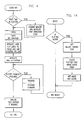
- the general sequence for the microprocessor 12, operating under program control, to process an IPC command is shown in FIG. 4.
- the microprocessor first determines if this is the first time since, for example, a reset or datastream mode change, that a plotter command has been received. If so, the processor acquires sufficient memory for a plotter font definition table and initializes the table in user memory.
- This font identification table is similar to tables for, for example, fonts downloaded from the host to the user memory of the printer.
- the plotter font definition table contains pointers to the locations of the font "character”. When initialized, these pointers are set to zero in the table. If subsequently only one raster image derived from graphic commands is produced, there will only be one non-zero value in the font definition table.
- FIG. 7 A diagrammatic illustration of the font definition table is shown in FIG. 7.
- text character fonts are usually maintained in a columnar format, although some larger character images are maintained in the form of raster lines and designated raster fonts.
- the plotter images created by the execution of plotter commands are also maintained as raster fonts.
- the table includes certain flags, including a flag indicating that the font is a raster font if that is the case. Therefore, plotter fonts as well as other raster fonts are identifiable by the flag in the font definition table.
- the font definition table also contains data pointing to the image location for each of the raster fonts.
- a font definition table in the present printer can point to as many as 256 font images.
- the font definition table also has a field containing the font name. For the plotter font definition table, there is a name identifier to distinguish it from other raster font definition tables.
- the processor then parses (FIG. 4) the IPC command. This process shall be described in more detail subsequently, but in substance parsing the IPC command calls for analyzing the parameters contained in the command to locate the plotted image on the page and to set the various image attributes.
- a user window relative to the page, is defined.
- the location of this graphics window can be, for example, anywhere within the text page. It is located in accordance with the IPC command parameter with respect to the normal text coordinate system for the page.
- the window is a rectangle defined by its top left corner and bottom right corner, in an orientation and coordinate system in which the X direction is across the top of a portrait page (with zero being the top left paper corner) and the Y direction is down the left side of the portrait page.
- This window represents, in plotter terms, the hard clip limits for any graphic drawing order commands that are embedded in the IPC command. That is, if any of the drawing orders attempt to "draw” outside this window, the image is "clipped" such that a virtual cursor position is maintained but no printing will result outside that area.
- the hard clip limits for the window are set to the area formed by the intersection of the paper boundaries and the specified window. Typically the window falls within the page, as is the case for the window 25 and the page 21 of FIG. 1, and the hard clip limits are the window 25. If no window is defined by IPC command parameters, the hard clip limits are substantially equal to the paper boundaries.
- the processor next initializes scaling factors so that, if the processor is scaling plotter command distances (such as the length of the line 24 in FIG. 1) the scaling factor is stored for each orthogonal direction of the plot.
- the processor then processes each of the plotter commands contained in the plotter command portion 32 (FIG. 2) of the IPC command. This process shall be described in more detail subsequently, but substantially the plotter commands are executed to place lines into the window, which is assigned a memory location in the user memory. After all of the plotter commands have been executed, the text cursor is placed in the proper position and the processing of the IPC command is complete. Depending upon a parameter setting in the IPC command, the cursor for the next text command can be returned to the position it had prior to the IPC command or left at its location at the end of execution of the plotter commands.
- the first IPC parameter which is one byte in length
- the first parameter byte includes a first (most significant) two bits which identify the units for positioning the window on the page.
- the units required to define the two points (upper left and lower right) of the window rectangle can be in any one of three unit systems in the present printer.
- One unit is 1/1016 inch (plotter units), and two alternative units are 1/1440 inch or 1/1200 inch.
- the printer controller will (when auto-scaling is selected or on by default) automatically scale the incoming graphic image to fit within the window that has been specified.
- the IPC command is structured to allow an application running on the host computer to only know the size in bytes of a previously generated plotter source command file. In this way the preface IPC command byte can be added by the application software to the beginning of the plotter data to be sent directly to the printer.
- the host application need not know how large the resultant plot would be on the paper, since the auto-scaling feature scales the plot to fit within the specified user window on the page.
- the next bit in the first parameter byte is to set color simulation. In this mode the plotted lines can take different dot and dash forms for different colors.
- the next bit sets enhanced mode (which changes the quality of downloaded plotter characteristics) on or off.
- the next bit can force low resolution mode. In low resolution mode, every other bit of the image produced in the window is stored in the horizontal and vertical directions to reduce the amount of user memory necessary to hold the plotted image. This mode is selected whether or not designated by the printer controller if there is insufficient user memory for a full resolution image to be stored, but sufficient memory for storing the plotted image in low resolution.
- the stored bits of a low resolution plotter image are doubled in the horizontal and vertical directions at rasterization to restore the size of the image.
- the next-to-last bit in the first parameter byte selects whether the cursor is to be restored to the previous text position or left at the last pen position as set by the plotter commands.
- the first parameter byte has all the bits, including the last bit, set to zero, the previous values for the above-described parameters are used. If the first parameter byte is set to one (all bits zero but the least significant bit), the parameters are set to the power-on reset default values. These default values are noted in the figure.
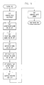
- the proces in parsing an IPC command, the processor, in the first six steps of FIG. 5, sets flags for the six parameter values contained in the first parameter byte (FIG. 6).
- the processor sets the window location and size based on the next four parameters, which establish the X and Y coordinates of the upper left and lower right corners of the window, utilizing the units set in the first step.
- the processor next sets the plotter command byte count, which is the difference between the command length 29 value (FIG, 2) and the parameter length 30 value (including the size of the field 30 itself). In processing plotter commands, the processor will utilze this number of bytes and then return to parsing text characters and commands. After setting the command byte count, the processor has completed parsing the IPC command.
- the plotter command being processed in the flowchart of FIG. 8 might be to draw a line from the point 41 to the point 42 (FIG. 1). If this command and its associated parameters are valid, the processor determines if a font image is active into which to draw the line. If the command and parameters are not valid, the command is not processed, and the processor proceeds to the next plotter command.
- a font image is active if the user memory needed for the raster data for the window has been set aside for a previous plotter command. Typically, this is true, and the processor then proceeds to clip the line data to the active window. Any part of the line, such as the part 43 of the line 24 (FIG> 1) falling outside the window boundaries is not written.
- the orientation of the plotter window coincides with the orientation of the text page.
- the plotter data in the window can be rotated relative to this orientation. Therefore, when the processor clips a line to the active window, rotation is applied, if called for by the plotter command.
- the processor then digitizes the clipped and rotated line into the font image. This ends the processing for one plotter command.
- the processor checks to see if an image is available for use by looking images in use in a cache table.
- An exemplary cache table is shown diagram strictlymatically in FIG. 9. For each window of image data stored in user memory, an entry is made in the cache table to show the boundaries of the image windoe, its resolution, and the like. The processor can then determine if the image area now needed matches, or fits within, an already existing image window. If an image is available in the cache table, the processor uses pointer values to the appropriate font definition table code point to find the window. The processor then activates the image thus identified in the cache table. The processor next proceeds to clip and digitize into the now active image area.
- the processor will attempt to create a suitable image area in user memory. If there is a memory available for a new image area, the processor allocates memory for the image from the user memory, activating the image area, and places appropriate pointer information (as shall be described subsequently) in the page buffer. Therefore, when the contents of the page buffer are rasterized, the pro cessor can access the image data from this image area. The processor also at this time places the appropriate entries in the cache table. The processor then clips and digitizes the line as before.
- the processor determines if there is sufficient memory to store the data in low resolution mode. If so, the processor selects low resolution mode for digitizing the commands and proceeds to allocate the memory as discussed earlier. If there is insufficient memory for even low resolution storage in an image area, the microprocessor is unable to process the plotter command and proceeds to the next plotter command. The processor does not simply disregard the balance of the plotter commands in an IPC command in this instance since some plotter commands reduce the requisite window size, permitting subsequent plotter commands to be processed.
- plotter commands are received embedded within a text command, known as an IPC command.
- the microprocessor in the controller of the printer parses the IPC command to establish certain environmental information for the plot produced by the plotter commands.
- the plotter commands are then processed into a raster image as defined by the plotter commands. This raster image is stored in user memory in the printer RAM in the form of a large font image.
- the processor stores a pointer and other information concerning the plotter "font" together with conventional text characters and movement commands.
- the plotter "font” is also written into the bit map memory. This merges the plotter and text data in the bit map without requiring processing of plotter commands by the host computer and without requiring processing of the plotter commands at the time of rasterization.
- the composite bit map containing text and plotter images is then serialized to the print engine to produce the printed output.
- the page buffer is organized in the form of packets of text, packets of image data and packets of raster font information.
- the exemplary printer is a partial page bit map printer employing swathing for rasterization.
- the practice of the invention is not limited to particular page buffer or bit map memory architectures, but the description of further aspects of the invention will be in conjunction with the present printer for exemplary purposes.
- the technique for the deletion of plotter image areas in user memory no longer needed for rasterization shall be described in association with the exemplary printer.
- the page 21 is arranged in the form in which it is presented to the print engine during serialization and in which it is subsequently reproduced on paper.
- the page 21 is not present in bit map memory in its entirety but is represented sequentially in a series of swaths, such as 51, 52, in the bit map memory proceeding from the top of the page to the bottom.
- swaths such as 51, 52
- the swath 52 is being serialized to the print engine, while swaths below the swath 51 have not yet been rasterized.
- the page contents include text areas 22 and 23 and the window 25 of plotter graphics, including the line 24.
- Each of these areas of the page is stored in a page buffer in the order in which that area of the page was received by the printer as separate "packets" of data in the page buffer.
- a packet is terminated (and a new packet begun) if there is a change in the character font, if the character mode (such as bold or double wide) changes if there is any upward movement of the location of characters on the page.
- Image data is also packetized.
- the image data is organized into a raster scan format before being placed into a packet.
- a packet of inmage data is terminated if there is a change in the resolution of the image data or upward movement on the page.
- each image is a separate packet.
- the page buffer entry for the packet does not include the raster image data but instead pointer information to the "large font" in the user memory.
- the text area 22 is organized as a packet in the page buffer, and, assuming for example that the text 23 is in a different font, the text 23 is in a second packet.
- the data for the window 25, including the line 24, is pointed to by a packet, as will be descibed subsequently.
- the input data for the page 21 to be printed is stored in the form of packets, without indexing, where the data within each packet is in printing order but the packets themselves are in the order received from the host, which typically is not in the printing order.
- a page 61 stored in the page buffer includes a page header 62 and a number of packets such as 63. Pages 61 are stored one after another in the page buffer, and packets such as 63 are stored one after another within each page.
- the page header 62 includes an end-of-page pointer 64, which indicates the starting point in the page buffer for a subsequent page if there is one.
- Each packet such as 63 includes a packet header 65 and usually includes packet data 66.
- the packet data is the information stored in the page buffer utilized in rasterizing the bit map swaths.
- the packet header contains certain identifying information concerning the contents and status of the packet.
- the packet header size may vary for different packet types.
- the header length for each packet type is a stored value.
- the packet data length is stored in the packet header, as shall be described subsequently.
- a text packet includes a packet header and packet data in the form of character and move codes.
- An image packet includes a packet header with identifying information and packet data in the form of bytes of all-points-addressable data.
- a packet for plotter data such as for the contents of the window 25 in the page 21 (FIG. 1), contains a packet header with identifying information but no packet data. The identifying information directs the processor to the font data stored in user memory for use during rasterization. This type of packet is also used to represent other raster fonts such as large alphanumeric characters which are stored in user memory.
- an exemplary packet header 65 for a raster font packet includes flags 67, a packet offset value 68, a packet length value 69, a bit map restart address 70 and a bit map starting address 71.
- the flags 67 in the packet header include flags for indicating the packet type (raster font packet), an end-of-page flag, an end-of-page buffer flag, and flags for rasterization attributes of half high, double wide, and double high.
- the length field 69 is set to zero, since there is no packet data in the packet.
- the offset field 68 is initialized to the height of the raster font character in raster lines. As indicated earlier, the stored graphics information for a graphic window is stored as a raster font character, and the height of the character in raster lines is substantially equivalent to the height of the window in raster lines.
- the bit map address 71 is the logical address in the bit map of the page for the placement of the first data to be rasterized from the packet.
- the bit map restart address 70 is the address for the next data to be rasterized into the bit map.
- the font identification field contains a byte which identifies the plotter font definition table and permits the processor to find that table.
- Other (non-plotter) raster fonts would contain other font identificationfield data.
- the pitch field 73 has two bytes which contain the width of the character (in this case the plotter window).
- the character code point field identifies the character in the font definition table.
- the index field 75 is initialized at zero and is used to hold the actual pointer to the character image data.
- the printer controller rasterizes each page from the page buffer, it moves down the page from swath to swath. For each swath which is processed, the microprocessor visits each packet of data for the page to determine if there is a contribution from that packet to the swath. This operation is shown in the flowchart of FIG. 12. In navigating through the packets of a page to rasterize a swath, the processor first examines the page header.
- the page buffer data on an inter-packet basis, can "wrap" from the bottom of the page buffer memory to the top. Therefore, the processor examines the page header to determine if a flag is set indicating that the balance of the page packets have wrapped to the beginning of the page buffer. If so, the processor moves to the top of the page buffer. If not, the processor moves to the address of the next packet. This address is determined from header information concerning the type of packet (the page header is a special type of packet), which determines the length of the header, combined with the length of the data portion of the packet (which in the case of a page header is zero).
- the processor determines what the offset value is in the packet addressed and if this offset is not equal to the length of the packet.
- the processor next determines if the restart bit map address is in swath being rasterized. The address of interest will either lie within the swath being rasterized or below it. If the restart address is not in the active swath, the packet is not processed. If the bit address is in the swath being rasterized, the packet is processed to place the appropriate data in the packet into the swath, as will be described in conjunction with the flowchart of FIG. 13, which deals with the rasterization of a raster font packet.
- a raster font packet contains a length of zero and an offset initialized to the height of the character in raster lines.
- the offset value is reduced to a value corresponding to the number of raster lines left to be rasterized for that font character (or plotter window in the case of a plotter image).
- the offset is initialized to zero and incremented as text data is rasterized until the offset value increases to equal the length value.
- the processor After rasterization of some or all of a packet, or in the case that there is no data to be rasterized from the packet, the processor then determines if it has reached the last packet in the page. If not, the processor loops to check for buffer wrap and proceeds through the above-described sequence of steps. If the processor is at the end of the page, the rasterization of that swath has been completed.
- the printer microprocessor in storing input data in the page buffer, accepts data received in an orderly fashion as part of a single packet of data. These packets of page buffer data are stored in the order received and are not linked or indexed in any fashion. Then, at the time of rasterization, the processor examines each packet for each swath that is rasterized. Packets that have been fully rasterized already, are disregarded; and the processor rasterizes the relevant parts of the other packets into the swath.
- the microprocessor in order to rasterize the data for a raster font packet, the microprocessor first sets the vertical and horizontal expansion modes, based upon the setting of the double wide and double high flags in the packet header. When low resolution has been called for in processing an IPC command, these bits will be set for double wide and double high.
- the processor next determines if the index value (in the field 75 of FIG. 11), is equal to zero. If so, the address of the image is obtained using the font identification field value and the character code point value. In the case of a non-zero index, indicating that at least part of the raster font data has been rasterized into the bit map, the processor sets the address of the image in the swath from the index value.
- the processor then computes the number of lines to process for the swath and for each line to be processed rasterizes each data word from that line. As each data word is moved to the bit map, the index value is incremented. When a line is completed, the cursor is incremented to the next line. After the last line of the image lying within the swath has been processed for the swath, the processor updates the bit map restart value in the field 70 and the index value in the field 75 in the packet header. This completes the processing of the raster font for a swath.
- the processor If there was plotter data for the just-printed page, the processor first sets a delete pending flag in system memory, indicating that there are one or more plotter data areas in user memory which can be deleted. The processor then deletes the plotter font image cache table from user memory and sets an image not active flag, indicating that no image blocks are active on the now-current page. The processor then exits the routine.
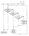
- the blocks of image to be deleted In order to actually delete plotter image data from the user memory, the blocks of image to be deleted must be marked. To do this, when time is available from rasterization and serialization, or when there is a request for memory such as for more page buffer memory, the processor executes a "mark blocks" routine as shown in FIG. 15. In this routine, the processor first marks all of the plotter font definition table entries for deletion. The processor then points to the top of the page buffer. If there are no blocks of plotter data to be used in any unprinted page, the processor exits the routine. All of the table entries in the plotter font definition table having been marked for deletion, the plotter images in user memory will be deleted subsequently when a routine is executed to actually recover the memory used by the blocks marked for deletion.
- the processor examines each packet in each page in the page buffer to determine if there is a plotter font present. For each such plotter font, the delete indication in the font definition table for that plotter font is changed to a "save" indication.
- the processor After examining each packet of each page in the page buffer, the processor looks for each entry in the font definition table marked for deletion which is a non-zero value and marks the image block to which the font definition table points for deletion. These plotter data blocks are then subsequently deleted as indicated before when the processor eliminates plotter data blocks from the user memory.
Landscapes
- Engineering & Computer Science (AREA)
- General Engineering & Computer Science (AREA)
- Physics & Mathematics (AREA)
- General Physics & Mathematics (AREA)
- Theoretical Computer Science (AREA)
- Record Information Processing For Printing (AREA)
- Dot-Matrix Printers And Others (AREA)
- Accessory Devices And Overall Control Thereof (AREA)
Applications Claiming Priority (2)
| Application Number | Priority Date | Filing Date | Title |
|---|---|---|---|
| US405603 | 1989-09-08 | ||
| US07/405,603 US5001653A (en) | 1989-09-08 | 1989-09-08 | Merging plotter graphics within a text environment on a page printer |
Publications (3)
| Publication Number | Publication Date |
|---|---|
| EP0423051A2 true EP0423051A2 (de) | 1991-04-17 |
| EP0423051A3 EP0423051A3 (en) | 1992-08-12 |
| EP0423051B1 EP0423051B1 (de) | 1996-04-10 |
Family
ID=23604378
Family Applications (1)
| Application Number | Title | Priority Date | Filing Date |
|---|---|---|---|
| EP90480102A Expired - Lifetime EP0423051B1 (de) | 1989-09-08 | 1990-07-18 | Seitendrucker in dem Plottergraphiken in einen Text eingefügt werden |
Country Status (4)
| Country | Link |
|---|---|
| US (1) | US5001653A (de) |
| EP (1) | EP0423051B1 (de) |
| JP (1) | JPH0751371B2 (de) |
| DE (1) | DE69026457T2 (de) |
Cited By (2)
| Publication number | Priority date | Publication date | Assignee | Title |
|---|---|---|---|---|
| EP0889434A3 (de) * | 1997-06-30 | 2001-05-02 | Hewlett-Packard Company, A Delaware Corporation | Druckersystem und Verfahren um für ankommende Daten Datenhinweise zu senden |
| CN100378643C (zh) * | 2004-12-10 | 2008-04-02 | 三星电子株式会社 | 编辑用于打印输出的文档的设备及其方法 |
Families Citing this family (30)
| Publication number | Priority date | Publication date | Assignee | Title |
|---|---|---|---|---|
| US5163368B1 (en) * | 1988-08-19 | 1999-08-24 | Presstek Inc | Printing apparatus with image error correction and ink regulation control |
| US5140674A (en) * | 1988-09-23 | 1992-08-18 | Hewlett-Packard Company | Text and color printing system |
| JP2610993B2 (ja) * | 1989-05-17 | 1997-05-14 | キヤノン株式会社 | 情報処理装置及び方法 |
| JP3135243B2 (ja) * | 1989-11-28 | 2001-02-13 | キヤノン株式会社 | 画像データ送受信方法及びそれに使用する装置 |
| US5089144B1 (en) * | 1989-12-08 | 1996-11-12 | Nartron Corp | Filter condition indicator having moveable sensor and aggregate flow counter |
| JPH0792775B2 (ja) * | 1989-12-11 | 1995-10-09 | 株式会社日立製作所 | 外部記憶装置群のスペース管理方法 |
| JP2844575B2 (ja) * | 1990-04-19 | 1999-01-06 | キヤノン株式会社 | 印刷装置 |
| JPH0426890A (ja) * | 1990-05-22 | 1992-01-30 | Sharp Corp | 文字表示装置 |
| JP2560133B2 (ja) * | 1990-05-29 | 1996-12-04 | 大日本スクリーン製造株式会社 | 画像統合処理装置 |
| US5315698A (en) * | 1991-08-21 | 1994-05-24 | Digital Equipment Corporation | Method and apparatus for varying command length in a computer graphics system |
| US5321806A (en) * | 1991-08-21 | 1994-06-14 | Digital Equipment Corporation | Method and apparatus for transmitting graphics command in a computer graphics system |
| US5383027A (en) * | 1992-02-27 | 1995-01-17 | Lifetouch National School Studios Inc. | Portrait printer system with digital image processing editing |
| US5500924A (en) * | 1992-05-07 | 1996-03-19 | Apple Computer, Inc. | Method for vector plotting a bitmap with a reduced number of lines |
| JP2862441B2 (ja) * | 1992-07-09 | 1999-03-03 | キヤノン株式会社 | 出力制御装置及び方法 |
| US5835690A (en) * | 1992-12-15 | 1998-11-10 | Microsoft Corporation | Header/footer text string parsing using callback routines for additional processing |
| US5848184A (en) * | 1993-03-15 | 1998-12-08 | Unisys Corporation | Document page analyzer and method |
| US5424945A (en) * | 1993-08-31 | 1995-06-13 | Xerox Corporation | System for evaluating a psychological effect of a document |
| US5960166A (en) * | 1993-10-01 | 1999-09-28 | Lexmark International, Inc. | Image printing solution for a printing device |
| EP0663659A3 (de) * | 1993-12-30 | 1995-11-22 | Ibm | Anzeige von Zeichen in einem Datenverarbeitungssystem. |
| US5590260A (en) * | 1993-12-30 | 1996-12-31 | International Business Machines Corporation | Method and apparatus for optimizing the display of fonts in a data processing system |
| DE69423208T2 (de) * | 1994-05-20 | 2000-07-06 | Clan Systems Ltd., Riccarton | Steuergerät für einen Drucker |
| US6243172B1 (en) * | 1995-01-18 | 2001-06-05 | Varis Corporation | Method and system for merging variable text and images into bitmaps defined by a page description language |
| US5729665A (en) * | 1995-01-18 | 1998-03-17 | Varis Corporation | Method of utilizing variable data fields with a page description language |
| US7302438B1 (en) | 1997-07-18 | 2007-11-27 | Tesseron Ltd. | Method and system for flowing data to an arbitrary path defined by a page description language |
| US6487568B1 (en) * | 1997-07-18 | 2002-11-26 | Tesseron, Ltd. | Method and system for flowing data to an arbitrary path defined by a page description language |
| US6166822A (en) * | 1998-01-20 | 2000-12-26 | Lexmark International, Inc. | Method of printing with a host based printer using an internal font |
| US7315979B1 (en) | 1998-11-09 | 2008-01-01 | Tesseron Ltd. | Method and system for dynamic flowing data to an arbitrary path defined by a page description language |
| US6972866B1 (en) * | 2000-10-03 | 2005-12-06 | Xerox Corporation | Detecting process neutral colors |
| US7170870B2 (en) * | 2002-05-07 | 2007-01-30 | Microsoft Corporation | Data packet transmission for channel-sharing collocated wireless devices |
| US20050179945A1 (en) * | 2004-02-12 | 2005-08-18 | Sharp Laboratories Of America, Inc. | System and method for variable text overlay |
Family Cites Families (13)
| Publication number | Priority date | Publication date | Assignee | Title |
|---|---|---|---|---|
| GB2038596B (en) * | 1978-12-20 | 1982-12-08 | Ibm | Raster display apparatus |
| JPS5781689A (en) * | 1980-11-10 | 1982-05-21 | Yokogawa Hokushin Electric Corp | Graphic form recording device |
| JPS5866181A (ja) * | 1981-10-15 | 1983-04-20 | Yokogawa Hokushin Electric Corp | 図形記録装置 |
| JPS59218493A (ja) * | 1983-05-25 | 1984-12-08 | シャープ株式会社 | 図形表示情報記憶方法 |
| JPS6319954A (ja) * | 1986-07-12 | 1988-01-27 | Ricoh Co Ltd | プロツタ制御装置 |
| JPS6352195A (ja) * | 1986-08-22 | 1988-03-05 | 日立デバイスエンジニアリング株式会社 | 表示制御システム |
| JPS63274550A (ja) * | 1987-05-02 | 1988-11-11 | Hitachi Ltd | 画像出力方式 |
| EP0310712B1 (de) * | 1987-10-05 | 1993-09-01 | Océ-Nederland B.V. | Integrales Eingang-Ausgangssystem für Rastabtast-Druckeinheit |
| US4928243A (en) * | 1987-10-06 | 1990-05-22 | Preco Industries, Inc. | Method and system for printing graphics and text from vector-based computer aided source information |
| JPH01152579A (ja) * | 1987-12-09 | 1989-06-15 | Nippon Denso Co Ltd | 地図画像表示装置 |
| US4918624A (en) * | 1988-02-05 | 1990-04-17 | The United States Of America As Represented By The United States Department Of Energy | Vector generator scan converter |
| JP2711860B2 (ja) * | 1988-07-18 | 1998-02-10 | キヤノン株式会社 | 出力制御方法およびその装置 |
| JP3018337B2 (ja) * | 1988-09-17 | 2000-03-13 | ブラザー工業株式会社 | 画像処理装置 |
-
1989
- 1989-09-08 US US07/405,603 patent/US5001653A/en not_active Expired - Lifetime
-
1990
- 1990-07-18 DE DE69026457T patent/DE69026457T2/de not_active Expired - Lifetime
- 1990-07-18 EP EP90480102A patent/EP0423051B1/de not_active Expired - Lifetime
- 1990-08-20 JP JP2217260A patent/JPH0751371B2/ja not_active Expired - Fee Related
Cited By (2)
| Publication number | Priority date | Publication date | Assignee | Title |
|---|---|---|---|---|
| EP0889434A3 (de) * | 1997-06-30 | 2001-05-02 | Hewlett-Packard Company, A Delaware Corporation | Druckersystem und Verfahren um für ankommende Daten Datenhinweise zu senden |
| CN100378643C (zh) * | 2004-12-10 | 2008-04-02 | 三星电子株式会社 | 编辑用于打印输出的文档的设备及其方法 |
Also Published As
| Publication number | Publication date |
|---|---|
| US5001653A (en) | 1991-03-19 |
| JPH03104666A (ja) | 1991-05-01 |
| JPH0751371B2 (ja) | 1995-06-05 |
| EP0423051A3 (en) | 1992-08-12 |
| EP0423051B1 (de) | 1996-04-10 |
| DE69026457D1 (de) | 1996-05-15 |
| DE69026457T2 (de) | 1996-10-31 |
Similar Documents
| Publication | Publication Date | Title |
|---|---|---|
| US5001653A (en) | Merging plotter graphics within a text environment on a page printer | |
| US6771387B2 (en) | Method of utilizing variable data fields with a page description language | |
| EP0412925B1 (de) | Seitendruckerspeicherzuweisung | |
| US4300206A (en) | Flexible text and image generator for a raster printer | |
| US5805174A (en) | Display list architecture having two dimensional array of zones | |
| US7583397B2 (en) | Method for generating a display list | |
| US6611347B1 (en) | Print control apparatus, print control method, storage medium, and computer readable program performing a form overlay process | |
| US5233685A (en) | Method and apparatus for integrated graphical and textual character printing | |
| US5592593A (en) | Printing in data processing systems | |
| EP0398681A2 (de) | Ausgabegerät | |
| US6310693B1 (en) | Printing control apparatus and method, and printing system for reducing processing overhead | |
| EP0119396B1 (de) | Einrichtung und Verfahren zur Darstellung oder Anzeige von durch elektrische Signale dargestellte Daten | |
| EP0481787B1 (de) | Ausgabeverfahren und Gerät | |
| JP3825883B2 (ja) | 情報処理装置、情報処理方法、記憶媒体、及び、印刷システム | |
| JP3450961B2 (ja) | 印刷装置及びその制御方法 | |
| JPH11305962A (ja) | 印刷処理装置および印刷処理装置のデータ処理方法およびコンピュータが読み出し可能なプログラムを格納した記憶媒体 | |
| JPH11170656A (ja) | 画像出力装置及び方法 | |
| JP2001270172A (ja) | 画像形成装置及び画像形成装置におけるフォントデータ制御方法並びに記憶媒体 | |
| AU2004216608B2 (en) | Method for generating a display list | |
| JP2000033730A (ja) | 印刷装置とその制御方法及び印刷システム | |
| JPH11143654A (ja) | 印刷制御装置および印刷制御装置のデータ処理方法およびコンピュータが読み出し可能なプログラムを格納した記憶媒体 | |
| JPH05181626A (ja) | 印字装置 | |
| JPH08197789A (ja) | 文字処理装置及び印刷装置 | |
| JP2002234218A (ja) | プリンタ装置及びプリンタ制御方法、プリンタ制御プログラム並びに記録媒体 | |
| JPH08106524A (ja) | 文字記号変換装置 |
Legal Events
| Date | Code | Title | Description |
|---|---|---|---|
| PUAI | Public reference made under article 153(3) epc to a published international application that has entered the european phase |
Free format text: ORIGINAL CODE: 0009012 |
|
| 17P | Request for examination filed |
Effective date: 19901213 |
|
| AK | Designated contracting states |
Kind code of ref document: A2 Designated state(s): DE FR GB |
|
| RAP1 | Party data changed (applicant data changed or rights of an application transferred) |
Owner name: LEXMARK INTERNATIONAL, INC. |
|
| 111Z | Information provided on other rights and legal means of execution |
Free format text: DE FR GB |
|
| PUAL | Search report despatched |
Free format text: ORIGINAL CODE: 0009013 |
|
| AK | Designated contracting states |
Kind code of ref document: A3 Designated state(s): DE FR GB |
|
| 17Q | First examination report despatched |
Effective date: 19941215 |
|
| GRAH | Despatch of communication of intention to grant a patent |
Free format text: ORIGINAL CODE: EPIDOS IGRA |
|
| GRAA | (expected) grant |
Free format text: ORIGINAL CODE: 0009210 |
|
| AK | Designated contracting states |
Kind code of ref document: B1 Designated state(s): DE FR GB |
|
| REF | Corresponds to: |
Ref document number: 69026457 Country of ref document: DE Date of ref document: 19960515 |
|
| ET | Fr: translation filed | ||
| PLBE | No opposition filed within time limit |
Free format text: ORIGINAL CODE: 0009261 |
|
| STAA | Information on the status of an ep patent application or granted ep patent |
Free format text: STATUS: NO OPPOSITION FILED WITHIN TIME LIMIT |
|
| 26N | No opposition filed | ||
| REG | Reference to a national code |
Ref country code: GB Ref legal event code: IF02 |
|
| PGFP | Annual fee paid to national office [announced via postgrant information from national office to epo] |
Ref country code: FR Payment date: 20090717 Year of fee payment: 20 |
|
| PGFP | Annual fee paid to national office [announced via postgrant information from national office to epo] |
Ref country code: DE Payment date: 20090729 Year of fee payment: 20 Ref country code: GB Payment date: 20090727 Year of fee payment: 20 |
|
| REG | Reference to a national code |
Ref country code: GB Ref legal event code: PE20 Expiry date: 20100717 |
|
| PG25 | Lapsed in a contracting state [announced via postgrant information from national office to epo] |
Ref country code: GB Free format text: LAPSE BECAUSE OF EXPIRATION OF PROTECTION Effective date: 20100717 |
|
| PG25 | Lapsed in a contracting state [announced via postgrant information from national office to epo] |
Ref country code: DE Free format text: LAPSE BECAUSE OF EXPIRATION OF PROTECTION Effective date: 20100718 |