EP0423272B1 - Appareil permettant de couper des paquets de cigarettes en vue de recuperer le tabac contenu dans les cigarettes - Google Patents
Appareil permettant de couper des paquets de cigarettes en vue de recuperer le tabac contenu dans les cigarettes Download PDFInfo
- Publication number
- EP0423272B1 EP0423272B1 EP90905986A EP90905986A EP0423272B1 EP 0423272 B1 EP0423272 B1 EP 0423272B1 EP 90905986 A EP90905986 A EP 90905986A EP 90905986 A EP90905986 A EP 90905986A EP 0423272 B1 EP0423272 B1 EP 0423272B1
- Authority
- EP
- European Patent Office
- Prior art keywords
- conveyor
- packs
- pack
- velocity
- indexing
- Prior art date
- Legal status (The legal status is an assumption and is not a legal conclusion. Google has not performed a legal analysis and makes no representation as to the accuracy of the status listed.)
- Expired - Lifetime
Links
- 235000019504 cigarettes Nutrition 0.000 title claims abstract description 48
- 241000208125 Nicotiana Species 0.000 title claims abstract description 17
- 235000002637 Nicotiana tabacum Nutrition 0.000 title claims abstract description 17
- 238000005520 cutting process Methods 0.000 title claims abstract description 16
- 238000002360 preparation method Methods 0.000 title claims abstract description 4
- 238000011084 recovery Methods 0.000 title claims abstract 3
- XLYOFNOQVPJJNP-UHFFFAOYSA-N water Substances O XLYOFNOQVPJJNP-UHFFFAOYSA-N 0.000 claims abstract description 30
- 230000004044 response Effects 0.000 claims abstract description 3
- 230000000284 resting effect Effects 0.000 claims abstract description 3
- 230000002093 peripheral effect Effects 0.000 claims description 4
- 238000011144 upstream manufacturing Methods 0.000 description 5
- 239000012634 fragment Substances 0.000 description 4
- 239000000463 material Substances 0.000 description 4
- NOOLISFMXDJSKH-UTLUCORTSA-N (+)-Neomenthol Chemical compound CC(C)[C@@H]1CC[C@@H](C)C[C@@H]1O NOOLISFMXDJSKH-UTLUCORTSA-N 0.000 description 3
- NOOLISFMXDJSKH-UHFFFAOYSA-N DL-menthol Natural products CC(C)C1CCC(C)CC1O NOOLISFMXDJSKH-UHFFFAOYSA-N 0.000 description 3
- 238000004519 manufacturing process Methods 0.000 description 3
- 229940041616 menthol Drugs 0.000 description 3
- 230000008901 benefit Effects 0.000 description 2
- 238000000034 method Methods 0.000 description 2
- 230000003287 optical effect Effects 0.000 description 2
- 239000005022 packaging material Substances 0.000 description 2
- 239000000123 paper Substances 0.000 description 2
- 239000002245 particle Substances 0.000 description 2
- 230000008569 process Effects 0.000 description 2
- 229920000298 Cellophane Polymers 0.000 description 1
- 241000196324 Embryophyta Species 0.000 description 1
- 230000009471 action Effects 0.000 description 1
- 238000007664 blowing Methods 0.000 description 1
- 238000005516 engineering process Methods 0.000 description 1
- 239000011888 foil Substances 0.000 description 1
- 230000005484 gravity Effects 0.000 description 1
- 238000012423 maintenance Methods 0.000 description 1
- 230000007257 malfunction Effects 0.000 description 1
- 239000002184 metal Substances 0.000 description 1
- 239000003595 mist Substances 0.000 description 1
- 239000000203 mixture Substances 0.000 description 1
- 239000011087 paperboard Substances 0.000 description 1
- 230000032258 transport Effects 0.000 description 1
Images


Classifications
-
- B—PERFORMING OPERATIONS; TRANSPORTING
- B65—CONVEYING; PACKING; STORING; HANDLING THIN OR FILAMENTARY MATERIAL
- B65B—MACHINES, APPARATUS OR DEVICES FOR, OR METHODS OF, PACKAGING ARTICLES OR MATERIALS; UNPACKING
- B65B69/00—Unpacking of articles or materials, not otherwise provided for
- B65B69/0033—Unpacking of articles or materials, not otherwise provided for by cutting
-
- Y—GENERAL TAGGING OF NEW TECHNOLOGICAL DEVELOPMENTS; GENERAL TAGGING OF CROSS-SECTIONAL TECHNOLOGIES SPANNING OVER SEVERAL SECTIONS OF THE IPC; TECHNICAL SUBJECTS COVERED BY FORMER USPC CROSS-REFERENCE ART COLLECTIONS [XRACs] AND DIGESTS
- Y10—TECHNICAL SUBJECTS COVERED BY FORMER USPC
- Y10S—TECHNICAL SUBJECTS COVERED BY FORMER USPC CROSS-REFERENCE ART COLLECTIONS [XRACs] AND DIGESTS
- Y10S83/00—Cutting
- Y10S83/929—Particular nature of work or product
- Y10S83/946—Container
-
- Y—GENERAL TAGGING OF NEW TECHNOLOGICAL DEVELOPMENTS; GENERAL TAGGING OF CROSS-SECTIONAL TECHNOLOGIES SPANNING OVER SEVERAL SECTIONS OF THE IPC; TECHNICAL SUBJECTS COVERED BY FORMER USPC CROSS-REFERENCE ART COLLECTIONS [XRACs] AND DIGESTS
- Y10—TECHNICAL SUBJECTS COVERED BY FORMER USPC
- Y10T—TECHNICAL SUBJECTS COVERED BY FORMER US CLASSIFICATION
- Y10T83/00—Cutting
- Y10T83/202—With product handling means
- Y10T83/2072—By brush means
-
- Y—GENERAL TAGGING OF NEW TECHNOLOGICAL DEVELOPMENTS; GENERAL TAGGING OF CROSS-SECTIONAL TECHNOLOGIES SPANNING OVER SEVERAL SECTIONS OF THE IPC; TECHNICAL SUBJECTS COVERED BY FORMER USPC CROSS-REFERENCE ART COLLECTIONS [XRACs] AND DIGESTS
- Y10—TECHNICAL SUBJECTS COVERED BY FORMER USPC
- Y10T—TECHNICAL SUBJECTS COVERED BY FORMER US CLASSIFICATION
- Y10T83/00—Cutting
- Y10T83/202—With product handling means
- Y10T83/2092—Means to move, guide, or permit free fall or flight of product
- Y10T83/2192—Endless conveyor
- Y10T83/2194—And means to remove product therefrom
-
- Y—GENERAL TAGGING OF NEW TECHNOLOGICAL DEVELOPMENTS; GENERAL TAGGING OF CROSS-SECTIONAL TECHNOLOGIES SPANNING OVER SEVERAL SECTIONS OF THE IPC; TECHNICAL SUBJECTS COVERED BY FORMER USPC CROSS-REFERENCE ART COLLECTIONS [XRACs] AND DIGESTS
- Y10—TECHNICAL SUBJECTS COVERED BY FORMER USPC
- Y10T—TECHNICAL SUBJECTS COVERED BY FORMER US CLASSIFICATION
- Y10T83/00—Cutting
- Y10T83/364—By fluid blast and/or suction
-
- Y—GENERAL TAGGING OF NEW TECHNOLOGICAL DEVELOPMENTS; GENERAL TAGGING OF CROSS-SECTIONAL TECHNOLOGIES SPANNING OVER SEVERAL SECTIONS OF THE IPC; TECHNICAL SUBJECTS COVERED BY FORMER USPC CROSS-REFERENCE ART COLLECTIONS [XRACs] AND DIGESTS
- Y10—TECHNICAL SUBJECTS COVERED BY FORMER USPC
- Y10T—TECHNICAL SUBJECTS COVERED BY FORMER US CLASSIFICATION
- Y10T83/00—Cutting
- Y10T83/647—With means to convey work relative to tool station
- Y10T83/6569—With means to stop work conveyor
-
- Y—GENERAL TAGGING OF NEW TECHNOLOGICAL DEVELOPMENTS; GENERAL TAGGING OF CROSS-SECTIONAL TECHNOLOGIES SPANNING OVER SEVERAL SECTIONS OF THE IPC; TECHNICAL SUBJECTS COVERED BY FORMER USPC CROSS-REFERENCE ART COLLECTIONS [XRACs] AND DIGESTS
- Y10—TECHNICAL SUBJECTS COVERED BY FORMER USPC
- Y10T—TECHNICAL SUBJECTS COVERED BY FORMER US CLASSIFICATION
- Y10T83/00—Cutting
- Y10T83/647—With means to convey work relative to tool station
- Y10T83/6579—With means to press work to work-carrier
-
- Y—GENERAL TAGGING OF NEW TECHNOLOGICAL DEVELOPMENTS; GENERAL TAGGING OF CROSS-SECTIONAL TECHNOLOGIES SPANNING OVER SEVERAL SECTIONS OF THE IPC; TECHNICAL SUBJECTS COVERED BY FORMER USPC CROSS-REFERENCE ART COLLECTIONS [XRACs] AND DIGESTS
- Y10—TECHNICAL SUBJECTS COVERED BY FORMER USPC
- Y10T—TECHNICAL SUBJECTS COVERED BY FORMER US CLASSIFICATION
- Y10T83/00—Cutting
- Y10T83/647—With means to convey work relative to tool station
- Y10T83/6582—Tool between tandem arranged work carrying means
-
- Y—GENERAL TAGGING OF NEW TECHNOLOGICAL DEVELOPMENTS; GENERAL TAGGING OF CROSS-SECTIONAL TECHNOLOGIES SPANNING OVER SEVERAL SECTIONS OF THE IPC; TECHNICAL SUBJECTS COVERED BY FORMER USPC CROSS-REFERENCE ART COLLECTIONS [XRACs] AND DIGESTS
- Y10—TECHNICAL SUBJECTS COVERED BY FORMER USPC
- Y10T—TECHNICAL SUBJECTS COVERED BY FORMER US CLASSIFICATION
- Y10T83/00—Cutting
- Y10T83/647—With means to convey work relative to tool station
- Y10T83/6584—Cut made parallel to direction of and during work movement
- Y10T83/6633—By work moving flexible chain or conveyor
-
- Y—GENERAL TAGGING OF NEW TECHNOLOGICAL DEVELOPMENTS; GENERAL TAGGING OF CROSS-SECTIONAL TECHNOLOGIES SPANNING OVER SEVERAL SECTIONS OF THE IPC; TECHNICAL SUBJECTS COVERED BY FORMER USPC CROSS-REFERENCE ART COLLECTIONS [XRACs] AND DIGESTS
- Y10—TECHNICAL SUBJECTS COVERED BY FORMER USPC
- Y10T—TECHNICAL SUBJECTS COVERED BY FORMER US CLASSIFICATION
- Y10T83/00—Cutting
- Y10T83/748—With work immobilizer
- Y10T83/7593—Work-stop abutment
Definitions
- the reclaiming of the tobacco from the finished, packaged product requires, of course, first opening the cartons and packs, then removing the cigarettes from the packs and finally separating the tobacco from the cigarette wrappers and the filters (in the case of filter-tipped cigarettes).
- a part of the tobacco reclaiming process that has proven to be very troublesome to carry out using high speed automatic equipment is that of opening the packs in such a way as to leave the packaging materials (cellophane outer wrapper, paper wrapper and foil inner wrapper) in large pieces, that is, free of small pieces that are not easily separated later on from the tobacco. Also, it is desirable, but not easy, to separate the tobacco from the cigarette wrappers and filters (where involved) in a manner that leaves large pieces of wrappers and largely intact filter plugs, free of slivers and other small pieces.
- An object of the present invention is to provide apparatus for opening cigarette packs in preparation for reclaiming the tobacco that produces a minimum of small fragments of packaging materials that are difficult to separate from the tobacco, and in particular, apparatus that cuts the packages and cigarettes cleanly without tearing or shredding.
- Another object is to provide equipment that will operate reliably with a minimum of downtime for maintenance or as a result of malfunction.
- Still another object is to permit the-handling and opening of the packages to be carried out at high speed, thereby maximizing the throughput and reducing the investment in equipment and plant space required to handle a high volume of product.
- another object is to have the ability to handle cigarette packs of different sizes and packs of both filter and non-filter cigarettes.
- apparatus for cutting cigarette packs comprises a first belt conveyor driven at a first velocity, a collator device for delivering the cigarette packs in collated relation onto the first conveyor with all packs resting on one of their larger sides and oriented lengthwise of the conveyor, and a second belt conveyor arranged coaxially with and adjacent to the downstream end of first conveyor to receive the packs from the first conveyor and driven at a second velocity.
- the second velocity is higher than the first velocity such that the packs become spaced apart end-to-end on the second conveyor.
- An indexing conveyor is arranged orthogonally to and adjacent to the end of the second conveyor downstream to receive each pack from the second conveyor at a receiving station.
- a detector device detects the arrival of each pack at the receiving station and produces a signal indicative thereof, and a drive device advances the indexing conveyor one step to move all packs thereon a selected distance greater than the width of the largest size pack in response to each such signal and thereafter causes the indexing conveyor to dwell until the next pack arrives and is detected at the receiving station.
- Each pack and all of the cigarettes therein are cut transversely as the packs move along on the indexing conveyor.
- the machine is designed to receive and cut apart transversely packs of cigarettes that contain tobaccos of blends sufficiently similar to enable them to be used together in making new cigarettes.
- the packs supplied to the machine are previously sorted to exclude cigarettes that are dissimilar. For example, menthol cigarettes will be previously sorted out.
- the machine is designed to handle packs of different sizes and both filter and non-filter cigarettes delivered to the machine at random. Accordingly the sorting process prior to delivery of the packs to the machine is much simpler than would be necessary if only packs of the same size or cigarettes of the same type (filter or non-filter) could be processed.
- the first element of the machine is a centrifugal collator 10, to which the cigarette packs are delivered by a feed hopper 12 from a conveyor (not shown) that is controlled, such as by a detector (not shown) associated with the collator 10, to deliver packs periodically to the hopper 12 when the contents of the hopper in relatively low.
- the collator 10 is per se a well-known device (see, for example, U.S. Patents Nos. 3,224,554, 3,065,839 and 2,662,632) for aligning and feeding similar articles end to end and flatwise. It has rotating, conical shaped bottom wall 14, a stationary outer wall 16 and an outlet trough 18.
- a stationary separator ring set in from the wall 16 and spaced above the bottom by a distance slightly greater than the narrower transverse dimension (thickness) of the thickest packs to be processor.
- Most packs ted to the collator almost immediately fall flatwise onto the bottom 14 and slide outwardly by centrifugal force to the perimeter and under the separator ring up against the perimeter wall 16.
- Many of the packs also by centrifugal force, become oriented with their longest axes (lengthwise) oriented in the circumferential direction. Packs that do not initially tall flatwise are rejected by the separator ring and encounter a rapidly rotating rejector roll located near the outlet through 18, which propels them generally inwardly.
- a guide deflects packs which lie flatwise but are not oriented circumferentially either to the rejector roll or reorients them to the desired circumferential orientation. Sooner or later, all packs received by the collator 10 end up flatwise and circumferentially oriented for delivery from the collator in an end to end row through the delivery trough 18.
- a first belt conveyor 20 (“CONVEYOR I"), moving in the direction indicated by the arrow V1 in Fig. 1, receives the packs from the trough 18.
- a drooping link chain retarder 22 (indicated schematically) which engages two or three of the packs at a time and by its weight increases the frictional force between the packs it engages and the belt, thereby slowing the packs down to the velocity of the belt 20.
- the bottom of the collator 10 is driven at a peripheral speed slightly greater than the speed of the conveyor 20 so that any gaps between packs leaving the collator are taken up on the conveyor 20; the collator can overfeed the conveyor by pushing the packs faster than the belt, but the chain retarder slows the packs to the speed of the conveyor. At times the packs may back up end to end into the collator; on the other hand there can be occasional gaps between packs on the conveyer 20.
- the operation of the collator is somewhat variable, but it has the important practical advantages of being simple, inexpensive, trouble-free and fast.
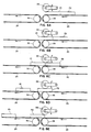
- the dancer roll 22 restrains the pack from being pulled off the belt 20 by the belt 24 because the frictional force between the pack and the belt 20 is greater than that between the pack and the belt 24.
- the dancer roll is centered over or slightly upstream of the downstream drive roll 26 of the belt to ensure pack P1 is not pulled from the belt 20 until it is distant from the dancer roll (Fig. 6C). At this point the pack P1 is picked up by the faster belt 24 and is quickly accelerated to the speed V2 of the faster belt.
- the next following pack P2 continues to travel at the velocity V1 of the belt 20.
- a space between the packs P1 and P2 forms (Figs. 6D and 6E).
- the space of course, remains after the pack P2 is picked up by the faster belt 24, so the packs are transported to the downstream end of the second conveyor 24 in spaced-apart relation.
- the dancer roll 22 or an equivalent device is important to establish substantial consistency of the points of transfer of all packs relative to their trailing ends.
- the dancer roll is advantageous because it is insensitive to the lengths of the packs. Cigarettes are usually 80 mm, 100 mm or 120 mm in length, and the dancer roll accommodates all of those sizes. It is also simple and reliable and requires no drive and no electronics to establish the spacing between packs that is required for subsequent handling of the packs.
- the belt conveyors 20 and 24 are driven by a common belt drive 28 (Fig. 1, of course with different sized belts and pulleys for the respective belts) associated with belt carrier rolls 26 and 30 (e.g., Fig. 6A).
- a common belt drive 28 Fig. 1, of course with different sized belts and pulleys for the respective belts
- belt carrier rolls 26 and 30 e.g., Fig. 6A.
- Each belt 20 and 24 has guide rails along both sides spaced-apart a distance slightly greater than the width of the widest packs to be processed by the machine.
- a roller bridge located downstream from the downstream end of the second conveyor 24 is a powered brush impeller 32 (shown schematically on Fig. 1), which is positioned so that the bristles engage the packs as they arrive and are pushed onto the bridge.
- the brush is rotated at a relatively high peripheral speed such as to propel each pack rapidly into the receiving station of an indexing conveyor 34.
- the roller bridge is simply a series of transverse rolls mounted on a frame that provides a low friction support for the packs between the end of the second conveyor 24 and the indexing conveyor 34 and provides minimum frictional restraint on the action of the brushes in transferring the packs to the indexing conveyor.
- the indexing conveyor 34 has a pair of side frame members 36 and 38 built up from plates and angles and joined by upper and lower crosspieces 40 and 42 at suitable intervals.
- a pair of upper chain tracks 44 and 46 are mounted on the upper crosspieces, and a pair of lower chain tracks 48 and 50 are mounted on the lower crosspieces.
- a stationary bed 52 which consists of a metal structural supporting member 54 and a low friction supported member 56.
- an endless roller link chain 58 and 60 On either side of the bed 52 is an endless roller link chain 58 and 60.
- Each chain is stretched between sprockets 62 (only one is shown in part in Fig. 3) carried by shafts journalled in the side frames 36 and 38 at the upstream and downstream ends of the index conveyor.
- the mechanical details of the sprockets, shafts and journals are not shown in the drawings because they are, of course, conventional in machine design. Also, in Fig. 2 the details of the chains are omitted for clarity.
- Every other link of the chain 60 carries a pusher bar 64 that extends inwardly and transversely partway across the top of the bed 52 along the upper run of the chain and is supported along the lower run by a support rail 66.
- every other link of the chain 58 carries a pusher bar 68, which extends partway across the bed and is supported along the lower run by a support rail 70.
- the free inner ends of the respective pusher bars 64 and 68 are spaced apart so that the pusher bars do not pass through the water jet by which the packs are cut apart, as described below.
- the remaining links of the chain 60 receive stop members 78 which catch the packs as they are propelled by the power brush 32 onto the indexing conveyor and register the packs endwise for cutting along the desired location.
- Affixed to the remaining links of the chain 58 are bridge plate 80, which support the packs an they traverse the gap between the roller bridge and the bed 52 at the receiving station.
- the arrowed line RS in Fig. 2 designates the receiving station of the indexing conveyor and also points in the direction in which the packs move in arriving.
- a stationary guide block 82 affixed to the bed 52 at the gap between the ends of the pusher bars ensures that misaligned packs arriving on the conveyor do not catch on the end tips of the pusher bars 64. Rebounding of the packs off the stops 78 is controlled by a powered brush 84 above the receiving station of the conveyor.
- An optical sensor 86 of a photodetector 88 is installed under the bed and views the receiving station through a hole in the bed.
- the photodetector 88 signals over a line 92 a stepper drive 90, which drives the conveyor chains 58 and 60 via the downstream sprocket shaft.
- the stepper drive advances the chains, pusher bars, stops and bridges one step.
- the stepper drive is programmed to move the chains a distance equal to the spacing lengthwise of the conveyor between adjacent pusher bars. That spacing is slightly greater than the widths of the widest packs to be processed in the machines.
- the relative speeds of the conveyors 20 and 24 are established so that enough space in opened up between adjacent packs on the second conveyor 24 to provide time for transfer of the packs to the indexing conveyor. While a pack is flicked onto the indexing conveyor by the powered brush 32 and the conveyor indexed one step to present the next slot at the receiving station, the next following pack is still moving along the second conveyor 24.
- the transfer to the second conveyor provides a fairly uniform spacing between the packs and the second conveyor, and leaves fairly uniform open times for transfer of packs to the receiving station on the indexing conveyor and indexing one step.
- the start-stop indexing motion of the indexing conveyor can jiggle the packs such that they move away from the stops 78. Accordingly, just upstream from the water jet cutting station of the conveyor and above the bed is a powered brush 94 for pushing the packs back against the stops 78 as they pass under.
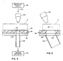
- a water jet cutter 96 is located near the downstream end of the indexing conveyor.
- the cutter system comprises a water jet supply 98, which is a commercially available unit that supplies water under very high pressure, a supply conduit 100 and a jet nozzle 102.
- the nozzle is positioned above the conveyor bed 54 and is oriented to direct the water jet obliquely against the packs P as they move under the nozzle with a velocity component in an upstream direction with respect to the direction of movement of the packs.
- the force of the water jet is quite high, and the bed 52 and pusher bar 64 and 68 are called upon to hold the packs against that force.
- the orientation of the water jet is such that the cut is initiated at the lower, leading comer of the pack, so there is no chance of tipping or ejection of the pack by the jet.
- the jet cuts very cleanly through the wrapping materials on the cigarettes, the cut advancing along the width of the pack as the conveyor moves the pack downstream.
- the clearance between the nearer ends of the pusher bars 64 and 68 is provided so that the jet does not impinge on them as they move through the cutter.
- the water jet exits from the packs and passes through a slot 104 in the conveyor bed 52 and into a discharge tube 106 that is sealed at a juncture 108 with the support plate 54 of the bed 52.
- the tube leads to a vacuum aspirator 110, which is simply a closed vessel at the lower end of the tube 106 that is coupled to a vacuum source.
- the vacuum aspirator 110 is very effective in sucking virtually all water that splashes, which is largely atomized particles like a mist, into the hole; the conveyor stays very clean over several hours of constant running of the machine.
- the jet When the jet impinges on the bottom of the aspirator collector vessel, it is atomized, and the water droplets and the particles of the wrappers and cigarettes removed by the jet are aspirated by the vacuum and carried through the vacuum line to a receiver tank.
- the vacuum aspirator system remains very clean in operation and is virtually maintenance-free.
- the water jet nozzle 102 is located transversely of the conveyor, relative to the stops 78, such that packs of all sizes and packs of both filter and non-filter cigarettes are cut cleanly along lines through the tobacco rod parts of all cigarettes. It does not matter which ends of the packs of filter-tipped cigarettes are against the stops.
- the ability to handle all sizes of packs and the absence of a need to orient filter cigarettes endwise is a significant advantage.
- the water jet cuts the packs very cleanly without making any rips or tears or severing small pieces of wrapping materials or the cigarettes.
- the two segments of the packs are indexed along the conveyor and dumped off the end to a take-away conveyor 112 (Fig. 1), which transports them to tobacco reclaiming equipment, such as the commercially available MCM Cigarette Reclaim System.
Landscapes
- Engineering & Computer Science (AREA)
- Mechanical Engineering (AREA)
- Manufacturing Of Cigar And Cigarette Tobacco (AREA)
- Control And Other Processes For Unpacking Of Materials (AREA)
Claims (13)
- Appareil permettant de couper des paquets de cigarettes transversalement en vue de récupérer le tabac contenu dans les cigarettes comprenant un premier convoyeur à bande entraîné suivant une première vitesse, des moyens pour fournir les paquets de cigarettes suivant une relation groupée ou assemblée sur le premier convoyeur, tous les paquets restant sur l'un de leurs plus grands côtés et sont orientés suivant la longueur du convoyeur, un deuxième convoyeur à bande disposé coaxialement avec et adjacent à l'extrémité avale du premier convoyeur pour recevoir les paquets du premier convoyeur et entraîné à une deuxième vitesse, la deuxième vitesse étant plus élevée que la première vitesse de sorte que les paquets deviennent espacés de bout-en-bout sur le deuxième convoyeur, un convoyeur d'indexation disposé orthogonalement à et adjacent à l'extrémité avale du deuxième convoyeur pour recevoir chaque paquet du deuxième convoyeur à une station de réception, des moyens pour détecter l'arrivée de chaque paquet à la station de réception et pour produire un signal indiquant ceux-ci, des moyens d'entraînement pour faire avancer le convoyeur d'indexation d'un pas pour déplacer tous les paquets sur celui-ci d'une distance choisie qui est plus grande que la largeur du paquet qui a les plus grandes dimensions en réponse à un tel signal et pour amener ensuite le convoyeur d'indexation à s'arrêter jusqu'à ce que le prochain paquet arrive et soit détecté à la station de réception ; et des moyens pour couper chaque paquet et les cigarettes contenues à l'intérieur transversalement au fur et à mesure qu'ils se déplacent sur le convoyeur d'indexation.
- Appareil selon la revendication 1, et comprenant en outre des moyens d'avancement à l'extrémité avale du deuxième convoyeur pour transférer chaque paquet à la station de réception du convoyeur d'indexation à une vitesse essentiellement plus grande que la deuxième vitesse.
- Appareil selon la revendication 1, dans lequel le moyen de coupe est un jet d'eau sous pression élevée.
- Appareil selon la revendication 1, dans lequel le convoyeur d'indexation comprend un lit stationnaire rigide s'étendant sur toute sa longueur et apte à supporter les paquets contre la force du choc du jet d'eau, et des barres de poussée entraînées par le moyen d'entraînement et pouvant venir en prise avec les paquets sur le convoyeur pour les faire avancer le long du lit.
- Appareil selon la revendication 4, dans lequel le lit présente un trou à travers lequel le jet d'eau passe après avoir coupé à travers les paquets et les cigarettes, et un tube est disposé dans une relation étanche au périmètre du trou sur le côté inférieur du lit pour recevoir et renfermer le jet d'eau.
- Appareil selon la revendication 5, comprenant en outre des moyens d'aspiration à vide couplés au tube pour maintenir un vide dans le tube et pour aspirer les projections d'eau du jet lorsqu'il heurte les paquets.
- Appareil selon la revendication 4, dans lequel le jet d'eau est dirigé contre les paquets suivant un angle oblique par rapport au lit avec un composant de vitesse dans une direction opposée à la direction de déplacement des paquets le long du convoyeur d'indexation, par quoi le jet heurte initialement le coin avant inférieur de chaque paquet lorsque la coupe débute et la coupe se propage vers le haut le long du bord avant du paquet.
- Appareil selon la revendication 1 et comprenant en outre un rouleau danseur tournant à l'extrémité du premier convoyeur qui est apte à maintenir un engagement de friction de chaque paquet avec le premier convoyeur pour un déplacement à la première vitesse jusqu'à ce qu'il se désengage du rouleau, par quoi le point de transfert du premier convoyeur au deuxième convoyeur relativement au bord arrière de chaque paquet est essentiellement uniforme de paquet en paquet, et l'uniformité essentielle de l'espacement entre les paquets sur le deuxième convoyeur est assuré.
- Appareil selon la revendication 2, dans lequel le moyen d'avancement est une brosse positionnée au-dessus des paquets, venant en prise avec les paquets et entraînée en rotation suivant une vitesse périphérique essentiellement plus grande que la vitesse du deuxième convoyeur.
- Appareil selon la revendication 4, dans lequel le convoyeur d'indexation comprend en outre une chaîne menée sans fin de chaque côté du lit et une rangée de barres de poussée espacées uniformément supportées par chacune des chaînes d'entraînement, les barres de poussée s'étendant orthogonalement au trajet de déplacement des paquets le long du lit, partiellement sur le lit en vue de l'engagement avec les parois latérales étroites arrières des paquets et présentant des extrémités libres espacées de sorte que les barres de poussée ne passent pas à travers le jet d'eau.
- Appareil selon la revendication 10, dans lequel la chaîne sur le côté du lit éloignée du deuxième convoyeur supporte des barres d'arrêt positionnées pour venir en prise avec les extrémités des paquets et pour établir leurs positions transversales sur le convoyeur d'indexation.
- Appareil selon la revendication 11, et comprenant en outre des moyens à la station de réception du convoyeur d'indexation pour agir contre des rebondissements des paquets arrivant et pour établir l'engagement des paquets avec les barres d'arrêt respectives.
- Appareil selon la revendication 12, dans lequel le moyen agissant contre les rebondissements est une brosse positionnée au-dessus des paquets, pouvant venir en prise avec ceux-ci et entraînée en rotation suivant une direction afin de les amener en engagement avec les barres d'arrêt respectives.
Priority Applications (1)
| Application Number | Priority Date | Filing Date | Title |
|---|---|---|---|
| AT90905986T ATE91101T1 (de) | 1989-04-04 | 1990-04-03 | Vorrichtung zum schneiden von zigarettenpackungen zwecks wiedergewinnung des tabaks in den zigaretten. |
Applications Claiming Priority (2)
| Application Number | Priority Date | Filing Date | Title |
|---|---|---|---|
| US07/333,122 US5001951A (en) | 1989-04-04 | 1989-04-04 | Apparatus for cutting apart cigarette packs in preparation for recovery of the tobacco in the cigarettes |
| US333122 | 1989-04-04 |
Publications (2)
| Publication Number | Publication Date |
|---|---|
| EP0423272A1 EP0423272A1 (fr) | 1991-04-24 |
| EP0423272B1 true EP0423272B1 (fr) | 1993-06-30 |
Family
ID=23301378
Family Applications (1)
| Application Number | Title | Priority Date | Filing Date |
|---|---|---|---|
| EP90905986A Expired - Lifetime EP0423272B1 (fr) | 1989-04-04 | 1990-04-03 | Appareil permettant de couper des paquets de cigarettes en vue de recuperer le tabac contenu dans les cigarettes |
Country Status (9)
| Country | Link |
|---|---|
| US (1) | US5001951A (fr) |
| EP (1) | EP0423272B1 (fr) |
| JP (1) | JPH04500493A (fr) |
| AT (1) | ATE91101T1 (fr) |
| BR (1) | BR9006283A (fr) |
| DE (1) | DE69002095T2 (fr) |
| DK (1) | DK0423272T3 (fr) |
| ES (1) | ES2044574T3 (fr) |
| WO (1) | WO1990011937A1 (fr) |
Families Citing this family (18)
| Publication number | Priority date | Publication date | Assignee | Title |
|---|---|---|---|---|
| US5234007A (en) * | 1990-03-13 | 1993-08-10 | R. J. Reynolds Tobacco Company | Method of and apparatus for reclaiming tobacco from cigarette packages |
| EP0580815B1 (fr) * | 1991-04-15 | 1998-01-21 | Lorillard Tobacco Company | Systeme de tri de paquets de cigarettes |
| DE4204786A1 (de) * | 1992-02-18 | 1993-08-19 | Hubert Hergeth | Verfahren und vorrichtung zum durchtrennen von verpackungen und ballenumreifungen |
| US5476354A (en) * | 1994-03-23 | 1995-12-19 | Brown & Williamson Tobacco Corporation | Method and apparatus for opening soft-cup cigarette packs |
| DE19505260A1 (de) * | 1995-02-16 | 1996-08-22 | Koehl Maschbau Gmbh | Verfahren und Vorrichtung zur Wiederverwertung fehlerhaft verpackter Zigaretten |
| US5752365A (en) * | 1996-12-09 | 1998-05-19 | General Mills, Inc. | Apparatus and methods for inserting premium items |
| US5870882A (en) * | 1997-03-26 | 1999-02-16 | Brown & Williamson Tobacco Corporation | System for automatically opening cartons and removing packages therein |
| US6098512A (en) * | 1998-04-17 | 2000-08-08 | Rockline Industries, Inc. | Multiple nozzle fluid cutting system for cutting webbed materials |
| US6514014B1 (en) | 2000-09-29 | 2003-02-04 | R. J. Reynolds Tobacco Company | Method and apparatus for collecting and transporting cigarettes and cigarette rejects |
| DE10135484A1 (de) * | 2001-07-20 | 2003-01-30 | Philip Morris Prod | Verfahren und Einrichtung zur Wertrückgewinnung von ausgesonderten Zigarettenpackungen |
| DE10301772A1 (de) * | 2003-01-18 | 2004-07-29 | Voith Paper Patent Gmbh | Wasserstrahlschneideinrichtung |
| PL211905B1 (pl) * | 2006-03-17 | 2012-07-31 | Int Tobacco Machinery Poland | Sposób i urządzenie do usuwania z opakowań powłoki z tworzywa sztucznego |
| AU2011224626A1 (en) * | 2010-03-08 | 2012-08-23 | Laitram, L.L.C. | Package-culling conveyor system and method |
| US20160120213A1 (en) | 2014-10-31 | 2016-05-05 | R. J. Reynolds Tobacco Company | Tobacco product component recovery system |
| US11033049B2 (en) | 2018-08-01 | 2021-06-15 | R.J. Reynolds Tobacco Company | Apparatus for recovering tobacco material and related method |
| CN110657728B (zh) * | 2019-08-27 | 2021-12-21 | 红云红河烟草(集团)有限责任公司 | 一种tobspin切丝机专用的切丝宽度检测定位工具 |
| US12030688B1 (en) * | 2020-08-27 | 2024-07-09 | Express Scripts Strategic Development, Inc. | Systems and methods for pharmaceutical container processing |
| EP4784493A1 (fr) | 2023-09-29 | 2026-08-05 | R. J. Reynolds Tobacco Company | Appareil et système de récupération de matériau à partir de produits enveloppés oraux et procédé associé |
Family Cites Families (16)
| Publication number | Priority date | Publication date | Assignee | Title |
|---|---|---|---|---|
| CH400049A (de) * | 1962-08-10 | 1965-10-15 | Buehler Ag Geb | Einrichtung zum selbsttätigen Abstreifen und nachfolgenden Schneiden von auf Tragstäben aufgehängten, strangförmigen Teigwaren |
| US3386320A (en) * | 1966-03-10 | 1968-06-04 | Reynolds Tobacco Co R | Package-opening method and apparatus |
| CH494692A (de) * | 1969-03-14 | 1970-08-15 | Haensel Otto Gmbh | Verfahren und Vorrichtung zum Abgeben von Gegenständen an eine Transporteinrichtung |
| IT967479B (it) * | 1972-09-15 | 1974-02-28 | Cavanna M | Dispositivo di regolazione dell ali mentazione di prodotti ad una macchina confezionatrice |
| US4137804A (en) * | 1974-07-12 | 1979-02-06 | Gerber Garment Technology, Inc. | Fluid cutting jet receiver |
| US4036380A (en) * | 1976-06-15 | 1977-07-19 | Loews Theatres, Inc. | Apparatus for opening cigarette cartons and packs and removing the cigarettes |
| US4083499A (en) * | 1976-11-15 | 1978-04-11 | Philip Morris Incorporated | Cigarette package ripper with recycling air leg |
| US4191199A (en) * | 1978-04-03 | 1980-03-04 | Brown & Williamson Tobacco Corporation | Apparatus and process for reclaiming tobacco |
| US4246838A (en) * | 1979-04-09 | 1981-01-27 | Velten & Pulver, Inc. | Multi-row dough slitting apparatus |
| US4442741A (en) * | 1982-09-07 | 1984-04-17 | Whittingham Thomas D | Meat log cutter |
| DE139775T1 (de) * | 1983-10-20 | 1986-04-10 | Tetra Pak International AB, Lund | Stau- und transportvorrichtung fuer gegenstaende. |
| US4622875A (en) * | 1984-03-23 | 1986-11-18 | Brown & Williamson Tobacco Corporation | System and process for sorting and opening packages |
| GB2158410A (en) * | 1984-05-03 | 1985-11-13 | Tingey & Company | Method and apparatus for use in de-packaging packaged goods |
| US4762219A (en) * | 1985-08-21 | 1988-08-09 | Pennwalt Corporation | Box conveying and indexing system |
| JPS6347014A (ja) * | 1986-08-11 | 1988-02-27 | Daito Seiki Kk | 鋼材等加工機用給材装置 |
| CH672293A5 (fr) * | 1987-03-23 | 1989-11-15 | Sig Schweiz Industrieges |
-
1989
- 1989-04-04 US US07/333,122 patent/US5001951A/en not_active Expired - Lifetime
-
1990
- 1990-04-03 BR BR909006283A patent/BR9006283A/pt not_active IP Right Cessation
- 1990-04-03 ES ES90905986T patent/ES2044574T3/es not_active Expired - Lifetime
- 1990-04-03 JP JP2505732A patent/JPH04500493A/ja active Pending
- 1990-04-03 WO PCT/US1990/001850 patent/WO1990011937A1/fr not_active Ceased
- 1990-04-03 AT AT90905986T patent/ATE91101T1/de not_active IP Right Cessation
- 1990-04-03 EP EP90905986A patent/EP0423272B1/fr not_active Expired - Lifetime
- 1990-04-03 DE DE90905986T patent/DE69002095T2/de not_active Expired - Fee Related
- 1990-04-03 DK DK90905986.7T patent/DK0423272T3/da active
Also Published As
| Publication number | Publication date |
|---|---|
| EP0423272A1 (fr) | 1991-04-24 |
| ES2044574T3 (es) | 1994-01-01 |
| WO1990011937A1 (fr) | 1990-10-18 |
| BR9006283A (pt) | 1991-08-06 |
| DE69002095T2 (de) | 1994-01-13 |
| DK0423272T3 (da) | 1993-12-13 |
| DE69002095D1 (de) | 1993-08-05 |
| US5001951A (en) | 1991-03-26 |
| JPH04500493A (ja) | 1992-01-30 |
| ATE91101T1 (de) | 1993-07-15 |
Similar Documents
| Publication | Publication Date | Title |
|---|---|---|
| US5001951A (en) | Apparatus for cutting apart cigarette packs in preparation for recovery of the tobacco in the cigarettes | |
| CA1299417C (fr) | Appareil servant a la production et au transport de decoupes de paquetsde cigarettes et procede connexe | |
| US4036380A (en) | Apparatus for opening cigarette cartons and packs and removing the cigarettes | |
| US5924840A (en) | Method of extracting contents from envelopes | |
| US5117843A (en) | Method of and apparatus for reclaiming tobacco from cigarette packages | |
| JPH0210007B2 (fr) | ||
| EP0525756B1 (fr) | Dispositif pour couper et enlever du matériau d'emballage | |
| EP2750525B1 (fr) | Récupération de tabac à partir de déchets de cigarettes | |
| US5234007A (en) | Method of and apparatus for reclaiming tobacco from cigarette packages | |
| KR100331389B1 (ko) | 포장된물품의포장해체에사용되는장치와방법 | |
| EP3197302B1 (fr) | Machine de fabrication d'articles pour fumeurs | |
| US5086790A (en) | Method of and apparatus for reclaiming cigarettes from cigarette packages | |
| EP0436304A1 (fr) | Procédé et appareil pour enlever le bout filtre des cigarettes défectueuses | |
| US4781091A (en) | Conveyor system for conveying veneer sheets with spacings therebetween | |
| EP0118289A2 (fr) | Procédé et appareil à l'usage de déballage de produits emballés | |
| US5870882A (en) | System for automatically opening cartons and removing packages therein | |
| GB2158410A (en) | Method and apparatus for use in de-packaging packaged goods | |
| US6514014B1 (en) | Method and apparatus for collecting and transporting cigarettes and cigarette rejects | |
| WO1992021566A1 (fr) | Appareil de deballage de pain | |
| JP3708988B2 (ja) | 長軸方向に搬送されたワークを横方向に移送する装置 | |
| JPS61205472A (ja) | タバコ加工産業の棒状の物品若しくはこの物品を形成するコンポーネントを搬送路から取除く方法及び装置 | |
| JPH0242728B2 (fr) | ||
| JPH03275428A (ja) | 包装体の包装を解除する方法およびその装置 | |
| EP1671553A1 (fr) | Appareil pour l'extraction de germes de végétaux | |
| JPH0912206A (ja) | 製袋機のデリバリ装置 |
Legal Events
| Date | Code | Title | Description |
|---|---|---|---|
| PUAI | Public reference made under article 153(3) epc to a published international application that has entered the european phase |
Free format text: ORIGINAL CODE: 0009012 |
|
| 17P | Request for examination filed |
Effective date: 19901222 |
|
| AK | Designated contracting states |
Kind code of ref document: A1 Designated state(s): AT BE CH DE DK ES FR GB IT LI LU NL SE |
|
| 17Q | First examination report despatched |
Effective date: 19920630 |
|
| GRAA | (expected) grant |
Free format text: ORIGINAL CODE: 0009210 |
|
| AK | Designated contracting states |
Kind code of ref document: B1 Designated state(s): AT BE CH DE DK ES FR GB IT LI LU NL SE |
|
| REF | Corresponds to: |
Ref document number: 91101 Country of ref document: AT Date of ref document: 19930715 Kind code of ref document: T |
|
| REF | Corresponds to: |
Ref document number: 69002095 Country of ref document: DE Date of ref document: 19930805 |
|
| ITF | It: translation for a ep patent filed | ||
| ET | Fr: translation filed | ||
| REG | Reference to a national code |
Ref country code: DK Ref legal event code: T3 |
|
| REG | Reference to a national code |
Ref country code: ES Ref legal event code: FG2A Ref document number: 2044574 Country of ref document: ES Kind code of ref document: T3 |
|
| PLBE | No opposition filed within time limit |
Free format text: ORIGINAL CODE: 0009261 |
|
| STAA | Information on the status of an ep patent application or granted ep patent |
Free format text: STATUS: NO OPPOSITION FILED WITHIN TIME LIMIT |
|
| 26N | No opposition filed | ||
| EPTA | Lu: last paid annual fee | ||
| EAL | Se: european patent in force in sweden |
Ref document number: 90905986.7 |
|
| PGFP | Annual fee paid to national office [announced via postgrant information from national office to epo] |
Ref country code: GB Payment date: 19970324 Year of fee payment: 8 |
|
| PGFP | Annual fee paid to national office [announced via postgrant information from national office to epo] |
Ref country code: ES Payment date: 19970408 Year of fee payment: 8 |
|
| PGFP | Annual fee paid to national office [announced via postgrant information from national office to epo] |
Ref country code: FR Payment date: 19970416 Year of fee payment: 8 |
|
| PGFP | Annual fee paid to national office [announced via postgrant information from national office to epo] |
Ref country code: SE Payment date: 19970418 Year of fee payment: 8 |
|
| PGFP | Annual fee paid to national office [announced via postgrant information from national office to epo] |
Ref country code: DE Payment date: 19970419 Year of fee payment: 8 |
|
| PGFP | Annual fee paid to national office [announced via postgrant information from national office to epo] |
Ref country code: LU Payment date: 19970422 Year of fee payment: 8 |
|
| PGFP | Annual fee paid to national office [announced via postgrant information from national office to epo] |
Ref country code: DK Payment date: 19970423 Year of fee payment: 8 Ref country code: BE Payment date: 19970423 Year of fee payment: 8 |
|
| PGFP | Annual fee paid to national office [announced via postgrant information from national office to epo] |
Ref country code: NL Payment date: 19970424 Year of fee payment: 8 Ref country code: AT Payment date: 19970424 Year of fee payment: 8 |
|
| PGFP | Annual fee paid to national office [announced via postgrant information from national office to epo] |
Ref country code: CH Payment date: 19970430 Year of fee payment: 8 |
|
| PG25 | Lapsed in a contracting state [announced via postgrant information from national office to epo] |
Ref country code: LU Free format text: LAPSE BECAUSE OF NON-PAYMENT OF DUE FEES Effective date: 19980403 Ref country code: GB Free format text: LAPSE BECAUSE OF NON-PAYMENT OF DUE FEES Effective date: 19980403 Ref country code: AT Free format text: LAPSE BECAUSE OF NON-PAYMENT OF DUE FEES Effective date: 19980403 |
|
| PG25 | Lapsed in a contracting state [announced via postgrant information from national office to epo] |
Ref country code: SE Free format text: LAPSE BECAUSE OF NON-PAYMENT OF DUE FEES Effective date: 19980404 Ref country code: ES Free format text: LAPSE BECAUSE OF NON-PAYMENT OF DUE FEES Effective date: 19980404 |
|
| PG25 | Lapsed in a contracting state [announced via postgrant information from national office to epo] |
Ref country code: LI Free format text: LAPSE BECAUSE OF NON-PAYMENT OF DUE FEES Effective date: 19980430 Ref country code: FR Free format text: THE PATENT HAS BEEN ANNULLED BY A DECISION OF A NATIONAL AUTHORITY Effective date: 19980430 Ref country code: DK Free format text: LAPSE BECAUSE OF NON-PAYMENT OF DUE FEES Effective date: 19980430 Ref country code: CH Free format text: LAPSE BECAUSE OF NON-PAYMENT OF DUE FEES Effective date: 19980430 Ref country code: BE Free format text: LAPSE BECAUSE OF NON-PAYMENT OF DUE FEES Effective date: 19980430 |
|
| BERE | Be: lapsed |
Owner name: LORILLARD INC. Effective date: 19980430 |
|
| PG25 | Lapsed in a contracting state [announced via postgrant information from national office to epo] |
Ref country code: NL Free format text: LAPSE BECAUSE OF NON-PAYMENT OF DUE FEES Effective date: 19981101 |
|
| GBPC | Gb: european patent ceased through non-payment of renewal fee |
Effective date: 19980403 |
|
| REG | Reference to a national code |
Ref country code: CH Ref legal event code: PL |
|
| NLV4 | Nl: lapsed or anulled due to non-payment of the annual fee |
Effective date: 19981101 |
|
| EUG | Se: european patent has lapsed |
Ref document number: 90905986.7 |
|
| PG25 | Lapsed in a contracting state [announced via postgrant information from national office to epo] |
Ref country code: DE Free format text: LAPSE BECAUSE OF NON-PAYMENT OF DUE FEES Effective date: 19990202 |
|
| REG | Reference to a national code |
Ref country code: FR Ref legal event code: ST |
|
| REG | Reference to a national code |
Ref country code: DK Ref legal event code: EBP |
|
| REG | Reference to a national code |
Ref country code: ES Ref legal event code: FD2A Effective date: 20000503 |
|
| PG25 | Lapsed in a contracting state [announced via postgrant information from national office to epo] |
Ref country code: IT Free format text: LAPSE BECAUSE OF NON-PAYMENT OF DUE FEES;WARNING: LAPSES OF ITALIAN PATENTS WITH EFFECTIVE DATE BEFORE 2007 MAY HAVE OCCURRED AT ANY TIME BEFORE 2007. THE CORRECT EFFECTIVE DATE MAY BE DIFFERENT FROM THE ONE RECORDED. Effective date: 20050403 |