EP0423305B1 - Vorrichtung zum beladen einer maschine zum schliessen der zehenenden von strümpfen in linie - Google Patents
Vorrichtung zum beladen einer maschine zum schliessen der zehenenden von strümpfen in linie Download PDFInfo
- Publication number
- EP0423305B1 EP0423305B1 EP90907254A EP90907254A EP0423305B1 EP 0423305 B1 EP0423305 B1 EP 0423305B1 EP 90907254 A EP90907254 A EP 90907254A EP 90907254 A EP90907254 A EP 90907254A EP 0423305 B1 EP0423305 B1 EP 0423305B1
- Authority
- EP
- European Patent Office
- Prior art keywords
- stockings
- supporting
- transfer
- transfer arm
- finger
- Prior art date
- Legal status (The legal status is an assumption and is not a legal conclusion. Google has not performed a legal analysis and makes no representation as to the accuracy of the status listed.)
- Expired - Lifetime
Links
- 238000000034 method Methods 0.000 claims description 8
- 230000000717 retained effect Effects 0.000 claims description 7
- 238000013459 approach Methods 0.000 description 1
- 239000011230 binding agent Substances 0.000 description 1
- 238000006073 displacement reaction Methods 0.000 description 1
- 238000004519 manufacturing process Methods 0.000 description 1
Images


Classifications
-
- D—TEXTILES; PAPER
- D05—SEWING; EMBROIDERING; TUFTING
- D05B—SEWING
- D05B23/00—Sewing apparatus or machines not otherwise provided for
- D05B23/007—Sewing units for assembling parts of knitted panties or closing the stocking toe part
Definitions
- the present invention relates to an apparatus for loading a line closing machine.
- US-A-4, 364, 320 describes a system for automatically closing the two portions of tubular hosiery blanks which includes an automatic loader assembly for receiving, supporting and spreading open an end portion of a hosiery blank for transporting the blank to a toe closing machine, and for carrying the opened end of the blank over a loading tube of a toe closing machine while everting the blank.
- the loader assembly has a blank support unit having loading fingers which are displaceable in a circular path about a hub.
- a binder or clamp is attached to a first loading finger for retaining the welt portion of the blank.
- the loading fingers extend to spread the welt portion and a drive motor displaces the garment to a position where the toe end of the blank is drawn into a loading tube. Continued displacement of the blank carries the blank over the exterior of the tube and the loading fingers then collapse, leaving the blank on the tube.
- EP-A-306, 460 discloses a method of loading a line closing machine which comprises supporting a pair of stockings by spaced apart support means at their open ends on a carousel.
- the stockings are supported in a first position with the ends of the stockings opening in a generally horizontal direction radially outwardly of the carousel unit.
- the stockings are moved through a transfer station to enable engagement of supporting means of the line closing machine into the open ends of the stockings.
- the support means are moved away from the supporting means such that the stockings are drawn from the support means and retained on the supporting means of the line closing machine.
- the present invention seeks to provide an apparatus for loading a line closing machine with stockings to be seamed into a pair of panti-hose.
- the present provides apparatus for loading a line closing machine of the type having a plurality of stocking supporting means for engaging in and supporting in vertically spaced relationship a pair of stockings
- the apparatus comprising: a carousel unit; a plurality of transfer arm means supported by said carousel unit; drive means for rotating the carousel unit to move each said transfer arm means successively through a loading station and at least one transfer station; wherein each said transfer arm means has support means for supporting a pair of stockings, and means for moving said support means between a first position for engaging said stockings on said stocking supporting means of said line closing machine and a second position for allowing said supporting means to disengage said stockings from said support means and leave said stockings engaged on said stocking supporting means during movement of said transfer arm through said transfer station; characterised in that wherein said support means comprises spaced apart finger means for supporting said stockings at the open ends thereof; and wherein said finger means are pivotable about a generally horizontal axis and said moving means is operable to pivot
- the present invention also provides a method of loading a line closing machine of the type having a plurality of stocking supporting means for engaging in and supporting in vertically spaced relationship a pair of stockings, the method comprising: supporting a pair of stocking by spaced apart support means at their open ends on a carousel, the stockings being supported in a first position with the ends of said stockings opening in a generally horizontal direction radially outwardly of said carousel unit; moving said stockings through a transfer station to enable engagement of said supporting means of said line closing machine into said open ends of said stockings; and at said transfer station moving said support means away from said supporting means such that said stockings are drawn from said support means and retained on said supporting means of said line closing machine; characterised by the further steps of: moving said support means apart from one another after loading of a pair of stockings on said support means, into an extended position such that the stockings are retained on the support means by the elasticity of the stockings; and moving said support means toward one another into
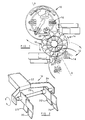
- Figure 1 shows two line closing machines 10, 12 with a preferred form of loading apparatus 14 according to the present invention positioned in alignment with and between the two line closing machines.
- Such line closing machines are well known and do not form part of this invention.
- Each line closing machine has six pairs of supporting arms 16 and the machines are arranged to rotate in the same direction (clockwise as seen in Figure 1), 30 degrees out of phase, such that the pairs of supporting arms of the two machines alternately present themselves to the loading apparatus to enable transfer of pairs of stockings from transfer arms 18 of the loading apparatus to supporting arms of the line closing machines at transfer stations 20.
- the loading apparatus is provided with twelve equally angularly spaced transfer arms 18, a first set (six) of these (every alternate one) cooperating with one of the line closing machines and a second set (the other six) cooperating with the other line closing machine.
- the loading apparatus 14 rotates in an anti-clockwise direction and as each alternate transfer arm 18 of those cooperating with the line closing machine 10 passes through a transfer station 20 the transfer arm is extended to enable transfer of the stockings.
- the extension of the transfer arms can be effected by suitable means such as fixed cams which act on a camming surface on each of the arms (described further below).
- Figure 2 shows a free end of a transfer arm of the loading apparatus, the arm having an elongate support member 22 which carries at its outer end a generally U-shaped bracket 24.
- the outer ends of the limbs of the U are joined by a shaft 26 on which are supported two pairs of support fingers 28, 30 and 32, 34.
- the pairs of fingers are slidable on the shaft 26 towards and away from each other and can also be pivoted from a generally horizontal attitude as shown in Figure 2, downwardly through 90 degrees to a generally vertical attitude.
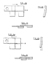
- each pair is movable relative to one another between a retracted position as shown in Figure 4 and an extended position as shown in Figure 3.
- the fingers are generally planar in shape and each finger has an upper portion which lies in a generally vertical plane and a lower portion which is angled outwardly at an angle of typically 15 degrees.
- Movement of the fingers towards and away from one another may be controlled by a simple piston/cylinder arrangement. Pivotal movement of fingers may also be controlled by a simple piston/cylinder arrangement or other suitable arrangement.
- an operator at a loading station loads two stockings for forming a pair of panti-hose onto the transfer arm fingers, one stocking being stretched across the fingers 28, 32 and the other stocking being stretched across the fingers 30, 34.
- the fact that the lower portions of the fingers are angled outwardly helps to retain the stockings on the fingers, the fingers being spaced sufficiently far apart so as to retain each stocking on the fingers by virtue of the elasticity of the waistband of each stocking.
- the fingers 28, 30 and 32, 34 of each pair are in their extended positions ( Figure 3a) to facilitate loading.
- FIG. 6 shows that as the transfer arm moves towards the associated transfer station 20 it moves towards a guide rail 36 of the line closing machine and a cooperating pair of supporting arms 16 of the line closing machine.
- the support member 22 of the transfer arm 18 is pivotally mounted at or adjacent its end remote from the fingers 28 to 34 to an elongate slide 50 by means of a generally horizontal pivot 52. This allows the support member 22 to pivot in a generally vertical plane from the generally horizontal attitude shown in Figure 7 to the raised position shown in Figure 9.
- the slide 50 is guided for axial sliding movement in a guide 54 so as to move the support member 22 along its axis, radially of the apparatus 14 between a retracted position and the extended position shown in Figure 9.
- Axial movement of the slide 50 and therefore of the support member 22 is effected by means of a cam which acts on a cam follower 58 secured to the underside of the slide 50.
- the slider 50 and support member 22 are biased into the retracted position by suitable resilient means (not shown) such as a coil spring.
- cam follower 58 moves along a cam track 60 which extends along a generally circular path.
- cam follower 58 is diverted from the generally circular path onto a further cam track 62 by a switch cam 64.
- the cam track 62 extends outwardly of the circular path, then generally parallel, and then back towards the circular path so that as the transfer arm 18 moves into the transfer station the cam follower 58 follows the cam 62 to extend the support member 22.
- the size of the fingers 28 to 34 and the spacing of the pairs of fingers are such as to allow the supporting arms 16 to penetrate into the stockings as can be seen in Figure 7, when the transfer arm 18 moves into the transfer station 20.
- the slider 52 and the support member 22 may be raised into the position shown in Figure 9. This is to ensure that the transfer arm 18 does not risk fouling any attachments which may be fitted either to the line closing machine or the loading apparatus.
- the cam follower 58 follows the trailing portion of the cam 62 to allow the transfer arm to retract. Once the transfer arm has passed out of the transfer station 20 the arm is lowered into its horizontal position.
- the cam 60 is continued along the generally circular path through the transfer station but is provided adjacent the leading end of the cam 62 with a cam switch 64 which is pivotable between a first position shown in dotted lines in Figure 10 and second position shown in solid lines.
- cam switch 64 When the cam switch 64 is in its second position it guides the cam follower 58 around the outer cam 62. However, when the cam switch 64 is in its first position the cam follower 58 is allowed to continue along the generally circular path of the cam 60.
- the downstream end portion 70 of the cam 62 is pivoted on the cam 62 such that it pivots out of the way when contacted by a cam follower 58 travelling inside the cam 62 to allow the cam follower to pass.
- the end portion 70 provides support for a cam follower 58 passing on the outside of the cam 62 since its free end rests on the cam 60.
- Actuation of the cam switch 64 may be effected by any suitable means, for example by an electric motor or solenoid, whilst the presence or absence of stockings on the transfer arm 18 may be monitored by any suitable means such as a light sensor which receives a beam of light which is interrupted by the presence of stockings, the signal from the sensor controlling actuation of the cam switch 64.
- the cam switch 64 and the corresponding cam switch at the two transfer stations are controlled to cause the first set of transfer arms 18 to extend at one of the transfer stations and the second set of transfer arms 18 to extend at the other transfer station so that the stockings on each alternate transfer arm are transferred at one station and the remaining stockings are transferred at the other station.
Landscapes
- Engineering & Computer Science (AREA)
- Textile Engineering (AREA)
- Treatment Of Fiber Materials (AREA)
- Sewing Machines And Sewing (AREA)
Claims (21)
- Vorrichtung zum Beladen einer Mittelnahtschließmaschine von dem Typ mit mehreren Strumpfhosenteilträgereinrichtungen (16), die in Eingriff mit einem Paar Strumpfhosenteilen gebracht werden und diese in senkrechtem Abstand voneinander halten sollen, wobei die Vorrichtung aufweist:
eine Karusselleinheit (14);
mehrere Übergabearm-Einrichtungen (18), die von der Karusselleinheit getragen werden;
Antriebseinrichtungen zum Drehen der Karusselleinheit, um jede der Übergabearm-Einrichtungen nacheinander durch eine Ladestation und mindestens eine Übergabestation (20) zu bewegen;
wobei jede der Übergabearm-Einrichtungen (18) Halteeinrichtungen zum Aufspannen eines Paars Strumpfhosenteile und Einrichtungen aufweist, um die Halteeinrichtungen während der Bewegung des Obergabearms durch die Übergabestation zwischen einer ersten Stellung, wo die Strumpfhosenteile mit der Strumpfhosenteilträgereinrichtung (16) der Mittelnahtschließmaschine (10, 12) in Eingriff zu bringen sind, und einer zweiten Stellung zu bewegen, damit die Trägereinrichtung die Strumpfhosenteile von den Halteeinrichtungen ablösen kann und die Strumpfhosenteile im Eingriff mit der Strumpfhosenteilträgereinrichtung (16) auf dieser zurückbleiben können;
dadurch gekennzeichnet, daß die Halteeinrichtungen beabstandete Fingereinrichtungen (28-34) zum Halten der Strumpfhosenteile an ihren offenen Enden aufweisen;
und daß die Fingereinrichtungen (28-34) um eine im allgemeinen horizontale Achse schwenkbar sind und die Bewegungseinrichtung so betätigt werden kann, daß sie die Fingereinrichtungen aus der ersten Stellung, in der die Enden der Strumpfhosenteile durch die Fingereinrichtungen so gehalten werden, daß sie sich in einer im allgemeinen horizontalen Richtung von der Karusselleinheit (14) radial nach außen öffnen, in eine zweite Stellung schwenkt, so daß durch das Schwenken der Fingereinrichtungen aus der ersten in die zweite Stellung die Strumpfhosenteilträgereinrichtung (16) der Mittelnahtschließmaschine die Strumpfhosenteile von den Fingereinrichtungen (28-34) abziehen kann, um die Strumpfhosenteile auf der Trägereinrichtung (16) festzuhalten, wenn die Trägereinrichtung an der Ubergabestation mit den Strumpfhosenteilen in Eingriff gebracht wird. - Vorrichtung nach Anspruch 1, wobei die Fingereinrichtungen (28-34) um einen Winkel von mindestens 45 Grad zwischen der ersten und der zweiten Stellung schwenkbar sind.
- Vorrichtung nach Anspruch 2, wobei die Fingereinrichtungen (28-34) um einen Winkel von mindestens 90 Grad schwenkbar sind.
- Vorrichtung nach einem der Ansprüche 1 bis 3, die ferner eine Einrichtung zum Verstellen des Abstands zwischen den Fingereinrichtungen (28-34) aufweist.
- Vorrichtung nach Anspruch 4, wobei die Verstelleinrichtung so funktioniert, daß sie die Fingereinrichtungen (28-34) zwischen einer ersten, ausgefahrenen Stellung, in welcher der Abstand zwischen den Fingereinrichtungen (28-34) so bemessen ist, daß die Strumpfhosenteile durch ihre Elastizität auf den Fingereinrichtungen festgehalten werden, und einer zweiten, eingefahrenen Stellung aufeinander zu und voneinander weg bewegt, um während der Bewegung der Fingereinrichtungen zwischen der ersten und der zweiten Stellung das Abziehen der Strumpfhosenteile von den Fingereinrichtungen (28-34) zu erleichtern.
- Vorrichtung nach einem der Ansprüche 1 bis 5, wobei jede der beabstandeten Fingereinrichtungen (28-34) erste und zweite, beabstandete Finger aufweist, wobei das erste Fingerpaar (28, 32) und das zweite Fingerpaar (30, 34) jeweils eines der Strumpfhosenteile aufnehmen.
- Vorrichtung nach Anspruch 6, wobei eines der Fingerpaare (28, 32; 30, 34) im Gleichtakt auf das andere Fingerpaar zu und von diesem weg bewegt werden kann, um das Beladen jedes einzelnen Fingerpaars mit einem entsprechenden Strumpfhosenteil durch einen Bediener der Beladestation zu erleichtern.
- Vorrichtung nach irgendeinem der vorstehenden Ansprüche die ferner eine Ausfahreinrichtung (58, 62) aufweist, um jede einzelne Übergabearm-Einrichtung (18) bei ihrer Bewegung in die Übergabestation (20) hinein ausfahren zu können, damit der Eingriff der Trägereinrichtung (16) der Mittelnahtschließmaschine (10, 12) in die Strumpfhosenteile erleichtert wird.
- Vorrichtung nach Anspruch 8, wobei die Ausfahreinrichtung eine Kurveneinrichtung (58, 62) an der Übergabearm-Einrichtung (18) und der Karusselleinheit (14) aufweist.
- Vorrichtung nach Anspruch 9, wobei die Kurveneinrichtung einen Kurvenstößel (58) an einer der Übergabearm-Einrichtungen (18) und der Karusselleinheit (14) und eine Kurvenfläche (62) an den anderen Übergabearm-Einrichtungen aufweist.
- Vorrichtung nach Anspruch 10, wobei der Kurvenstößel (58) von der Übergabearm-Einrichtung (18) getragen wird.
- Vorrichtung nach Anspruch 10 oder 11, wobei der Kurvenstößel (58) und die Kurvenfläche (62) so zusammenwirken, daß die Übergabearm-Einrichtung (18) bei ihrer Bewegung in die Übergabestation (20) hinein ausgefahren wird und bei ihrer Bewegung aus der Übergabestation (20) heraus eingefahren werden kann.
- Vorrichtung nach Anspruch 12, die ferner eine Wähleinrichtung (64, 70) aufweist, um während der Bewegung der Übergabearm-Einrichtung durch die Übergabestation (20) das Ausfahren einer vorher ausgewählten Übergabearm-Einrichtung (18) zu ermöglichen.
- Vorrichtung nach Anspruch 13, wobei die Wähleinrichtung (64, 70) eine Führungseinrichtung (64) einschließt, die zwischen einer ersten und einer zweiten Stellung beweglich ist, wobei die Führungseinrichtung in der ersten Stellung den Kurvenstößel (58) auf die Kurvenfläche (62) führt und in der zweiten Stellung den Kurvenstößel (58) auf eine zweite Kurvenfläche (60) führt, um die Übergabearm-Einrichtung (18) in der eingefahrenen Stellung zu halten.
- Vorrichtung nach Anspruch 14, wobei die Wähleinrichtung ferner einer Steuereinrichtung zum Steuern der Betätigung der Führungseinrichtung (64) aufweist, wobei die Steuereinrichtung so arbeitet, daß die Führungseinrichtung (64) zwischen einer ersten und einer zweiten Stellung umgeschaltet wird, je nachdem, ob auf den Halteeinrichtungen (28-34) ein Paar Strumpfhosenteile vorhanden sind oder nicht.
- Vorrichtung nach Anspruch 14, wobei die Karusselleinheit drehbar ist, um die Übergabearm-Einrichtungen (18) nacheinander durch eine Beladestation und zwei Übergabestationen (20) zu bewegen und die entsprechenden Mittelnahtschließmaschinen an den Übergabestationen zu beladen, und wobei die Wähleinrichtung eine Steuereinrichtung zum Steuern der Betätigung der jeweiligen Führungseinrichtung (64) an jeder Obergabestation (20) aufweist, wobei die Steuereinrichtung so arbeitet, daß sie jede Führungseinrichtung (64) zwischen einer ersten und e.iner zweiten Stellung umschaltet, um das Ausfahren aufeinanderfolgender geradzahliger Übergabearm-Einrichtungen (18) an der ersten Übergabestation (20) und das Ausfahren aufeinanderfolgender ungeradzahliger Übergabearm-Einrichtungen (18) an der zweiten Übergabestation (20) zu bewirken.
- Vorrichtung nach irgendeinem der vorstehenden Ansprüche, die ferner Einrichtungen zum elastischen Vorspannen jeder Übergabearm-Einrichtung (18) zur einer eingefahrenen Stellung hin aufweist.
- Verfahren zum Beladen einer Mittelnahtschließmaschine von dem Typ mit mehreren Strumpfhosenteilträgereinrichtungen (16), die in Eingriff mit einem Paar Strumpfhosenteilen gebracht werden und diese in senkrechtem Abstand voneinander halten sollen, wobei das Verfahren aufweist:
Aufspannen eines Paars Strumpfhosenteile an ihren offenen Enden durch beabstandete Halteeinrichtungen (28-34) auf einem Karussell (14), wobei die Strumpfhosenteile in einer ersten Stellung aufgespannt werden, in der sich die Enden der Strumpfhosenteile in einer im allgemeinen horizontalen Richtung von der Karusselleinheit (14) radial nach außen öffnen;
Bewegen der Strumpfhosenteile durch eine Obergabestation, um den Eingriff der Trägereinrichtung (16) der Mittelnahtschließmaschine (10, 12) in die offenen Enden der Strumpfhosenteile zu ermöglichen;
und an der Übergabestation (20) Bewegen der Halteeinrichtungen (28-34) von der Trägereinrichtung (16) weg, so daß die Strumpfhosenteile von den Halteeinrichtungen (28-34) abgezogen und auf der Trägereinrichtung (16) der Mittelnahtschließmaschine festgehalten werden;
gekennzeichnet durch die folgenden weiteren Schritte:
Auseinanderbewegen der Halteeinrichtungen (28-34) in eine ausgefahrene Stellung nach dem Beladen der Halteeinrichtungen mit einem Paar Strumpfhosenteile, so daß die Strumpfhosenteile durch ihre Elastizität auf den Halteeinrichtungen festgehalten werden;
und Zusammenbewegen der Halteeinrichtungen in eine zweite, eingefahrene Stellung an der Übergabestation nach dem Eingriff der Trägereinrichtung (16) in die Strumpfhosenteile, um bei der Bewegung der Halteeinrichtungen von der Trägereinrichtung (16) weg das Abziehen der Strumpfhosenteile von den Halteeinrichtungen (28-34) zu erleichtern. - Verfahren nach Anspruch 18, wobei der Schritt der Bewegung der Halteeinrichtungen (28-34) von der Trägereinrichtung weg eine Schwenkung der Halteeinrichtungen um einen Winkel von mindestens 45 Grad aufweist.
- Verfahren nach Anspruch 19, wobei die Halteeinrichtungen (28-34) um einen Winkel von mindestens 90 Grad geschwenkt werden.
- Verfahren nach einem der Ansprüche 18 bis 20, welches das Ausfahren der Halteeinrichtungen (28-34), um die Strumpfhosenteile bei ihrer Bewegung in die Übergabestation (20) hinein von dem Karussell radial nach außen zu verschieben und dadurch den Eingriff der Trägereinrichtung (16) der Mittelnahtschließmaschine (10, 12) in die Strumpfhosenteile zu erleichtern, und das Einfahren der Halteeinrichtungen (28-34) nach der Übergabe der Strumpfhosenteile an die Trägereinrichtung (16) aufweist.
Priority Applications (1)
| Application Number | Priority Date | Filing Date | Title |
|---|---|---|---|
| AT90907254T ATE97965T1 (de) | 1989-05-05 | 1990-05-03 | Vorrichtung zum beladen einer maschine zum schliessen der zehenenden von struempfen in linie. |
Applications Claiming Priority (2)
| Application Number | Priority Date | Filing Date | Title |
|---|---|---|---|
| GB8910318 | 1989-05-05 | ||
| GB898910318A GB8910318D0 (en) | 1989-05-05 | 1989-05-05 | Apparatus for loading a line closing machine |
Publications (2)
| Publication Number | Publication Date |
|---|---|
| EP0423305A1 EP0423305A1 (de) | 1991-04-24 |
| EP0423305B1 true EP0423305B1 (de) | 1993-12-01 |
Family
ID=10656255
Family Applications (1)
| Application Number | Title | Priority Date | Filing Date |
|---|---|---|---|
| EP90907254A Expired - Lifetime EP0423305B1 (de) | 1989-05-05 | 1990-05-03 | Vorrichtung zum beladen einer maschine zum schliessen der zehenenden von strümpfen in linie |
Country Status (8)
| Country | Link |
|---|---|
| US (1) | US5129337A (de) |
| EP (1) | EP0423305B1 (de) |
| JP (1) | JPH04500475A (de) |
| AU (1) | AU5535590A (de) |
| CA (1) | CA2032139A1 (de) |
| DE (1) | DE69004928D1 (de) |
| GB (2) | GB8910318D0 (de) |
| WO (1) | WO1990013697A1 (de) |
Families Citing this family (6)
| Publication number | Priority date | Publication date | Assignee | Title |
|---|---|---|---|---|
| US5165355A (en) * | 1991-03-26 | 1992-11-24 | Sara Lee Corporation | Method and apparatus for handling hosiery blanks |
| IT1252800B (it) * | 1991-09-18 | 1995-06-28 | Solis Srl | Macchina per la cucitura automatica della punta del piede di due calze, specialmente dei collants. |
| GB9402684D0 (en) * | 1994-02-11 | 1994-04-06 | Detexomat Machinery Ltd | A hosiery line closer and loader assembly |
| US5511501A (en) * | 1994-04-05 | 1996-04-30 | Monarch Knitting Machinery Corporation | Method and apparatus for handling flexible objects |
| US5544603A (en) * | 1994-04-05 | 1996-08-13 | Monarch Knitting Machinery Corporation | Apparatus for handling flexible objects |
| JP3122589B2 (ja) * | 1994-12-29 | 2001-01-09 | 株式会社タカトリ | パンティストッキング素材の装着方法 |
Family Cites Families (11)
| Publication number | Priority date | Publication date | Assignee | Title |
|---|---|---|---|---|
| JPS4822773B1 (de) * | 1970-11-19 | 1973-07-09 | ||
| US4188898A (en) * | 1977-09-06 | 1980-02-19 | Takatori Machinery Mfg. Co., Ltd. | System for combining stocking materials and gussets to form panty hose garments |
| JPS5731891A (en) * | 1980-07-31 | 1982-02-20 | Sukeo Mori | Inserting fitting device for stocking cloth in end automatic sewing machine for seamless stocking |
| US4364320A (en) * | 1981-02-23 | 1982-12-21 | Consolidated Foods Corporation | Garment toe closing system |
| US4539924A (en) * | 1981-08-28 | 1985-09-10 | Consolidated Foods Corporation | Loading system for a toe closing assembly |
| US4444140A (en) * | 1981-12-14 | 1984-04-24 | Monarch Knitting Machinery Corporation | Method of making panty hose and apparatus to make same |
| GB8409884D0 (en) * | 1984-04-17 | 1984-05-31 | Detexomat Machinery Ltd | Transporting fabric pieces |
| JPS61103481A (ja) * | 1984-10-24 | 1986-05-21 | 株式会社 タカトリ機械製作所 | パンテイストツキングの一貫縫製装置におけるパンテイストツキング脚部の搬送装置 |
| US4784070A (en) * | 1985-09-10 | 1988-11-15 | Detexomat Machinery Limited | Pantihose manufacture |
| IT1213803B (it) * | 1987-07-14 | 1990-01-05 | Solis Srl | Metodo e macchina per il trasferimento automatico dei collant e simili manufatti da unamacchina di cucitura delle punte ad una macchina da stiro |
| JPH01259892A (ja) * | 1988-04-11 | 1989-10-17 | Takatori Haitetsuku:Kk | パンテイストッキング素材の自動装着装置 |
-
1989
- 1989-05-05 GB GB898910318A patent/GB8910318D0/en active Pending
-
1990
- 1990-05-03 DE DE90907254T patent/DE69004928D1/de not_active Expired - Lifetime
- 1990-05-03 CA CA002032139A patent/CA2032139A1/en not_active Abandoned
- 1990-05-03 JP JP2506681A patent/JPH04500475A/ja active Pending
- 1990-05-03 US US07/634,870 patent/US5129337A/en not_active Expired - Fee Related
- 1990-05-03 WO PCT/GB1990/000684 patent/WO1990013697A1/en not_active Ceased
- 1990-05-03 AU AU55355/90A patent/AU5535590A/en not_active Abandoned
- 1990-05-03 EP EP90907254A patent/EP0423305B1/de not_active Expired - Lifetime
- 1990-05-04 GB GB9010101A patent/GB2231483B/en not_active Expired - Fee Related
Also Published As
| Publication number | Publication date |
|---|---|
| EP0423305A1 (de) | 1991-04-24 |
| WO1990013697A1 (en) | 1990-11-15 |
| GB9010101D0 (en) | 1990-06-27 |
| GB8910318D0 (en) | 1989-06-21 |
| GB2231483B (en) | 1993-06-16 |
| AU5535590A (en) | 1990-11-29 |
| US5129337A (en) | 1992-07-14 |
| GB2231483A (en) | 1990-11-21 |
| CA2032139A1 (en) | 1990-11-06 |
| JPH04500475A (ja) | 1992-01-30 |
| DE69004928D1 (de) | 1994-01-13 |
Similar Documents
| Publication | Publication Date | Title |
|---|---|---|
| CA2045796C (en) | Material handling system | |
| US4539924A (en) | Loading system for a toe closing assembly | |
| US5070709A (en) | Striping system for circular knitting machine | |
| US4364320A (en) | Garment toe closing system | |
| US3777683A (en) | Apparatus for manufacturing loops of elasticised material | |
| EP0219963B1 (de) | Herstellung von Strumpfhosen | |
| US5349913A (en) | Method and apparatus for attaching sleeves to tubular shirt bodies | |
| EP0740715A1 (de) | Verfahren und vorrichtung zum zusammenfügen von kleidungsstücken | |
| EP0423305B1 (de) | Vorrichtung zum beladen einer maschine zum schliessen der zehenenden von strümpfen in linie | |
| US4592295A (en) | Automatic shirt cuff manufacturing unit | |
| EP0710304B1 (de) | Verfahren zum schliessen von einem gestrickten produkt, wie ein socken oder dergleichen | |
| US4598817A (en) | Loading system for a toe closing assembly | |
| EP1585695A1 (de) | Vorrichtung und verfahren zum automatischen orientieren von strumpfware beim schliessen der strumpfenden | |
| US4602710A (en) | Loading system for a toe closing assembly | |
| US4383491A (en) | Method and apparatus for hosiery manufacture | |
| US7025011B2 (en) | Apparatus for automatically orienting hosiery articles for closing toe ends thereof | |
| KR102761241B1 (ko) | 양말류 등을 위한 원형 편직 기계로부터 관형 편직 제품을 제거하기 위한 제거 장치 | |
| GB2066862A (en) | Method and apparatus for seaming toes in hosiery manufacture | |
| US5255621A (en) | Turret pocket setter for tubular fabrics | |
| US4133277A (en) | Stocking toe end closing apparatus | |
| EP0281168A1 (de) | Einstellvorrichtung für die Radiallage der Platinen an einer Rundstrickmaschine | |
| EP1277870B1 (de) | Verfahren und Vorrichtung zum automatischen Aufziehen von Socken und dergleichen auf Formen | |
| US4336697A (en) | Method of and mechanism for transferring knitted fabric from a knitting machine to a magazine | |
| WO1994000630A9 (en) | Turret pocket setter for tubular fabrics | |
| GB2249321A (en) | Apparatus for transferring knitted fabric from circular knitting machine |
Legal Events
| Date | Code | Title | Description |
|---|---|---|---|
| PUAI | Public reference made under article 153(3) epc to a published international application that has entered the european phase |
Free format text: ORIGINAL CODE: 0009012 |
|
| 17P | Request for examination filed |
Effective date: 19910129 |
|
| AK | Designated contracting states |
Kind code of ref document: A1 Designated state(s): AT BE CH DE DK ES FR GB IT LI LU NL SE |
|
| 17Q | First examination report despatched |
Effective date: 19920527 |
|
| GRAA | (expected) grant |
Free format text: ORIGINAL CODE: 0009210 |
|
| ITF | It: translation for a ep patent filed | ||
| AK | Designated contracting states |
Kind code of ref document: B1 Designated state(s): AT BE CH DE DK ES FR GB IT LI LU NL SE |
|
| PG25 | Lapsed in a contracting state [announced via postgrant information from national office to epo] |
Ref country code: SE Effective date: 19931201 Ref country code: NL Effective date: 19931201 Ref country code: LI Effective date: 19931201 Ref country code: ES Free format text: THE PATENT HAS BEEN ANNULLED BY A DECISION OF A NATIONAL AUTHORITY Effective date: 19931201 Ref country code: DK Effective date: 19931201 Ref country code: DE Effective date: 19931201 Ref country code: CH Effective date: 19931201 Ref country code: BE Effective date: 19931201 Ref country code: AT Effective date: 19931201 |
|
| REF | Corresponds to: |
Ref document number: 97965 Country of ref document: AT Date of ref document: 19931215 Kind code of ref document: T |
|
| REF | Corresponds to: |
Ref document number: 69004928 Country of ref document: DE Date of ref document: 19940113 |
|
| REG | Reference to a national code |
Ref country code: CH Ref legal event code: PL |
|
| ET | Fr: translation filed | ||
| NLV1 | Nl: lapsed or annulled due to failure to fulfill the requirements of art. 29p and 29m of the patents act | ||
| PG25 | Lapsed in a contracting state [announced via postgrant information from national office to epo] |
Ref country code: LU Free format text: LAPSE BECAUSE OF NON-PAYMENT OF DUE FEES Effective date: 19940531 |
|
| PLBE | No opposition filed within time limit |
Free format text: ORIGINAL CODE: 0009261 |
|
| STAA | Information on the status of an ep patent application or granted ep patent |
Free format text: STATUS: NO OPPOSITION FILED WITHIN TIME LIMIT |
|
| 26N | No opposition filed | ||
| PGFP | Annual fee paid to national office [announced via postgrant information from national office to epo] |
Ref country code: GB Payment date: 19950525 Year of fee payment: 6 |
|
| PGFP | Annual fee paid to national office [announced via postgrant information from national office to epo] |
Ref country code: FR Payment date: 19950531 Year of fee payment: 6 |
|
| PG25 | Lapsed in a contracting state [announced via postgrant information from national office to epo] |
Ref country code: GB Effective date: 19960503 |
|
| GBPC | Gb: european patent ceased through non-payment of renewal fee |
Effective date: 19960503 |
|
| PG25 | Lapsed in a contracting state [announced via postgrant information from national office to epo] |
Ref country code: FR Effective date: 19970131 |
|
| REG | Reference to a national code |
Ref country code: FR Ref legal event code: ST |
|
| PG25 | Lapsed in a contracting state [announced via postgrant information from national office to epo] |
Ref country code: IT Free format text: LAPSE BECAUSE OF NON-PAYMENT OF DUE FEES;WARNING: LAPSES OF ITALIAN PATENTS WITH EFFECTIVE DATE BEFORE 2007 MAY HAVE OCCURRED AT ANY TIME BEFORE 2007. THE CORRECT EFFECTIVE DATE MAY BE DIFFERENT FROM THE ONE RECORDED. Effective date: 20050503 |