EP0423342B1 - Verfahren zur interpolation beim automatischen programmieren - Google Patents
Verfahren zur interpolation beim automatischen programmieren Download PDFInfo
- Publication number
- EP0423342B1 EP0423342B1 EP89913092A EP89913092A EP0423342B1 EP 0423342 B1 EP0423342 B1 EP 0423342B1 EP 89913092 A EP89913092 A EP 89913092A EP 89913092 A EP89913092 A EP 89913092A EP 0423342 B1 EP0423342 B1 EP 0423342B1
- Authority
- EP
- European Patent Office
- Prior art keywords
- target
- block
- target movement
- length
- last sub
- Prior art date
- Legal status (The legal status is an assumption and is not a legal conclusion. Google has not performed a legal analysis and makes no representation as to the accuracy of the status listed.)
- Expired - Lifetime
Links
Images


Classifications
-
- G—PHYSICS
- G05—CONTROLLING; REGULATING
- G05B—CONTROL OR REGULATING SYSTEMS IN GENERAL; FUNCTIONAL ELEMENTS OF SUCH SYSTEMS; MONITORING OR TESTING ARRANGEMENTS FOR SUCH SYSTEMS OR ELEMENTS
- G05B19/00—Program-control systems
- G05B19/02—Program-control systems electric
- G05B19/18—Numerical control [NC], i.e. automatically operating machines, in particular machine tools, e.g. in a manufacturing environment, so as to execute positioning, movement or co-ordinated operations by means of program data in numerical form
- G05B19/41—Numerical control [NC], i.e. automatically operating machines, in particular machine tools, e.g. in a manufacturing environment, so as to execute positioning, movement or co-ordinated operations by means of program data in numerical form characterised by interpolation, e.g. the computation of intermediate points between programmed end points to define the path to be followed and the rate of travel along that path
- G05B19/4103—Digital interpolation
-
- G—PHYSICS
- G05—CONTROLLING; REGULATING
- G05B—CONTROL OR REGULATING SYSTEMS IN GENERAL; FUNCTIONAL ELEMENTS OF SUCH SYSTEMS; MONITORING OR TESTING ARRANGEMENTS FOR SUCH SYSTEMS OR ELEMENTS
- G05B19/00—Program-control systems
- G05B19/02—Program-control systems electric
- G05B19/18—Numerical control [NC], i.e. automatically operating machines, in particular machine tools, e.g. in a manufacturing environment, so as to execute positioning, movement or co-ordinated operations by means of program data in numerical form
- G05B19/41—Numerical control [NC], i.e. automatically operating machines, in particular machine tools, e.g. in a manufacturing environment, so as to execute positioning, movement or co-ordinated operations by means of program data in numerical form characterised by interpolation, e.g. the computation of intermediate points between programmed end points to define the path to be followed and the rate of travel along that path
-
- G—PHYSICS
- G05—CONTROLLING; REGULATING
- G05B—CONTROL OR REGULATING SYSTEMS IN GENERAL; FUNCTIONAL ELEMENTS OF SUCH SYSTEMS; MONITORING OR TESTING ARRANGEMENTS FOR SUCH SYSTEMS OR ELEMENTS
- G05B2219/00—Program-control systems
- G05B2219/30—Nc systems
- G05B2219/34—Director, elements to supervisory
- G05B2219/34098—Slope fitting, fairing contour, curve fitting, transition
-
- G—PHYSICS
- G05—CONTROLLING; REGULATING
- G05B—CONTROL OR REGULATING SYSTEMS IN GENERAL; FUNCTIONAL ELEMENTS OF SUCH SYSTEMS; MONITORING OR TESTING ARRANGEMENTS FOR SUCH SYSTEMS OR ELEMENTS
- G05B2219/00—Program-control systems
- G05B2219/30—Nc systems
- G05B2219/34—Director, elements to supervisory
- G05B2219/34167—Coarse fine, macro microinterpolation, preprocessor
-
- G—PHYSICS
- G05—CONTROLLING; REGULATING
- G05B—CONTROL OR REGULATING SYSTEMS IN GENERAL; FUNCTIONAL ELEMENTS OF SUCH SYSTEMS; MONITORING OR TESTING ARRANGEMENTS FOR SUCH SYSTEMS OR ELEMENTS
- G05B2219/00—Program-control systems
- G05B2219/30—Nc systems
- G05B2219/34—Director, elements to supervisory
- G05B2219/34175—Overlap, between two blocks, continuous, smooth speed change, movement
-
- G—PHYSICS
- G05—CONTROLLING; REGULATING
- G05B—CONTROL OR REGULATING SYSTEMS IN GENERAL; FUNCTIONAL ELEMENTS OF SUCH SYSTEMS; MONITORING OR TESTING ARRANGEMENTS FOR SUCH SYSTEMS OR ELEMENTS
- G05B2219/00—Program-control systems
- G05B2219/30—Nc systems
- G05B2219/34—Director, elements to supervisory
- G05B2219/34176—Block segments, find next point on next segment by cross point circle and segment
-
- G—PHYSICS
- G05—CONTROLLING; REGULATING
- G05B—CONTROL OR REGULATING SYSTEMS IN GENERAL; FUNCTIONAL ELEMENTS OF SUCH SYSTEMS; MONITORING OR TESTING ARRANGEMENTS FOR SUCH SYSTEMS OR ELEMENTS
- G05B2219/00—Program-control systems
- G05B2219/30—Nc systems
- G05B2219/42—Servomotor, servo controller kind till VSS
- G05B2219/42207—Generate points between start and end position, linear interpolation
Definitions
- the present invention relates to an automatic programming method, and more particularly, to an interpolation method in an automatic programming method, which is capable of properly determining and programming target amounts of movement of individual axes to be used in each interpolation cycle at the time of execution of a numerical control program for contour control.
- a so-called contour control for machining a workpiece into a desired profile is conventionally known, in which actuators such as servomotors for the individual axes of a machine tool are driven under the control of a numerical control unit, to thereby move a tool along a target movement path.
- target movement data for each interpolation cycle is sequentially supplied from the numerical control unit at intervals of a predetermined interpolation cycle.
- the machining speed is decreased if a time period required for the calculation is long. Therefore, from the viewpoint of improving the machining speed, it is desired to create a numerical control program for the contour control in which the target positions of the individual axes in each interpolation processing cycle are previously programmed as execution data.
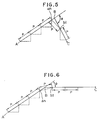
- the target amounts of movement of the servomotors for the individual axes in each of sub-sections are calculated and then programmed as execution data, the sub-sections being obtained by dividing each section, defined by the starting point A (Figs. 6 and 7) of an associated one block of the numerical control program consisting of a series of blocks and the target end point (starting point of the next block) B the same block determined by the movement command value of this block, by a length equal to a target movement amount P (the product of the target moving speed and one interpolation period) per interpolation period. If the target movement amount P per interpolation period does not divide the movement command, i.e., if the last sub-section is shorter than the target movement amount P (Fig.
- an overlapping process is effected to derive an intersection b1 at which a sphere, having the starting point an of the last sub-section as its center and the target movement amount P as its radius, crosses the target movement path of the next block. Then, the derived intersection b1 is used as the target end point of the last sub-section of one of the blocks relating to the overlapping process (which end point corresponds to the starting point of the first sub-section of the other block).
- the target movement amounts of the individual axes in the last interpolation cycle of one of the two blocks relating to the overlapping process will not be set to such an inappropriate value as to cause the target path (indicated by a broken line in the drawing) obtained after the overlapping process to be excessively deviated from the originally intended path (shown by a solid line in the drawing) and thus degradation in the machining precision.
- the angle ⁇ between the two target movement paths becomes larger, the target movement amounts for the individual axes after the overlapping process will be more inappropriate, thus lowering the machining precision (Fig. 7).
- An object of the present invention is to provide an interpolation method in automatic programming, which is capable of properly determining and programming target amounts of movement for individual axes to be used in each interpolation cycle at the time of execution of a numerical control program, thereby making it possible to improve the machining speed and machining precision.
- an interpolation method for producing in automatic programming a numerical program including execution data of a target path of a tool of an NC machine tool having plural axes, where the target path is composed of sections each of which is programmed as a block comprising the step of: (a) deriving target movement amounts for individual axes, with respect to a plurality of sub-sections which are obtained by dividing a section from a starting point to a target end point of each block, each sub-section being equal in length to a target movement amount per interpolation period; characterised by comprising the steps: (b) checking whether or not the length of a last sub-section in each of the blocks is smaller than the target movement amount; (c) checking whether or not a predetermined condition for permitting execution of an overlapping process between consecutive blocks is satisfied for each of the last sub-sections which are determined to have a length smaller than the target movement amount; (d) effecting the overlapping process to derive target movement amounts for individual axes in each of those last sub-section
- the target movement amounts for the individual axes are derived by the overlapping process when the length of the last one of the plurality of sub-sections obtained by dividing each of the blocks constituting the numerical control program is smaller than the target movement amount per interpolation period and the predetermined condition for the last sub-section is satisfied, whereas the target movement amounts of the individual axes in the last sub-section are derived without effecting the overlapping process when the predetermined condition is not satisfied. Accordingly, the machining speed can be prevented from being lowered and the machining precision can be improved, as compared with the case wherein the target movement amounts for the individual axes in all of the last sub-sections whose length is smaller than the target movement amount are derived by the overlapping process.
- the machining operation can be effected at the same machining speed as that for the other sub-sections without lowering the machining precision, thus making it possible to smoothly effect the machining operation.
- an interactive automatic programming apparatus which is known in the art and to which an interpolation method according to one embodiment of the present invention is applied, comprises a central processing unit (hereinafter referred to as CPU) 1, a read-only memory (ROM) 2 storing a control program for operating the programming apparatus, and a random-access memory (RAM) 3 for storing a numerical control (NC) program and for temporarily storing data which is processed by the CPU 1.
- the programming apparatus further includes a keyboard 4, a graphic display device (hereinafter referred to as CRT) 5, a data storage memory 6 for storing execution data, and a disk controller 7.
- the aforesaid elements 2 - 7 are connected to the CPU 1 through busses 9.
- the automatic programming apparatus is arranged to cause the RAM 3 to store an NC program, which is automatically created in response to operator's keyboard operations effected in light of various messages displayed on the CRT 5.
- the programming apparatus is also operable to read out, via the disk controller 7, an NC program prepared and stored in the floppy disk 8 beforehand, or read out, via a tape reader (not shown), an NC program prepared beforehand, and cause the RAM 3 to store the thus read program.
- the NC program of this embodiment is used to drive a tool of a machine tool (not shown) provided with an NC unit, by means of three servomotors for X-axis, Y-axis and Z-axis, so as to move the tool along a 3-dimensional tool path constructed by a plurality of sections which include two linear sections AB and BC, to thereby machine a workpiece (not shown) into a desired profile.
- the program includes a plurality of blocks corresponding to these sections and including movement commands.
- Each of the sections is constructed by a plurality of sub-sections having the same length as a target movement amount (the product of the interpolation period and the target moving speed) P per interpolation cycle and a last sub-section having a length which is the same as or smaller than the value P .
- the automatic programming apparatus is arranged to derive target amounts of movement of the individual axes for respective interpolation cycle in each of the blocks including the movement commands, and store the same as execution data. Further, during the execution of each of the blocks including the movement commands, the NC unit is operable to read out the programmed target movement amounts of the individual axes from the NC program and supply the same to servo-circuits (not shown) associated with the individual axes, without calculating target movement amounts for the individual axes in each interpolation period on a real time basis.
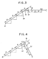
- the operator Prior to creation of execution data, the operator inputs, through the keyboard 4, a criterion value ⁇ s in relation to an angle ⁇ between the target movement paths (indicated, by way of example, by straight lines AB and BC in Fig. 3) of adjacent blocks, and a criterion value Ps in relation to the target movement amount in the last sub-section of each block, these criterion values being employed for determination as to whether or not the overlapping operation should be made.
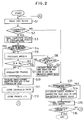
- the CPU 1 of the automatic programming apparatus causes the RAM 3 to store the criterion values ⁇ s and Ps. Whereupon, the CPU 1 starts the execution data creating process of Fig. 2 when an execution data creating command is input by the operator through the keyboard 4.
- the CPU 1 reads from the RAM 3 one of the blocks in the NC program, serving as the basis for creation of the execution data (step S1), and checks whether or not the movement command or interpolation command is included in the block (step S2). Since the first block, read out immediately after the start of the process of Fig. 2, does not include an interpolation command, the result of the determination at step S2 is negative (NO). Then, a determination is made as to whether or not the interpolation process is completed up to the target end point of a block preceding the block read out at step S1 (step S13). Since the determination result at step S13 regarding the first block is affirmative (YES), the instruction in the block read out at step S1 is stored in the data storage memory 6 (step S15). Next, the CPU determines whether or not a termination command is included in the block read out at step S1 (step S16). Since the determination result at step S16 regarding the first block is negative, step S1 is entered again and the next block is read out.
- step S2 of a certain execution data creation processing cycle that the block read out at step S1 of the same processing cycle includes an interpolation command
- the CPU reads the coordinate values of the starting point and the target end point (which are respectively indicated, by way of example, by symbols B and C in Fig. 3) in this block (step S3). Then, the CPU determines whether or not the interpolation process is completed up to the target end point B of the block immediately before the block read out at step S1 of the current processing cycle (step S4).
- step S10 is entered to start the interpolation process for the block read out at step S1 in the current processing cycle.
- the CPU divides the target movement amount of the current processing cycle by the target movement amount P per interpolation cycle, and determines a value n' of the integer part of the resultant quotient. Then, the CPU calculates the target movement amount (incremental amount) for each of the axes in each interpolation cycle, and causes the data storage memory 6 to repetitively store the thus calculated value required times corresponding to the aforesaid value n' (step S11).
- step S12 The product n'P of the value n' and the value P representative of the coordinate position of the target end point C or the coordinate position of the starting point bn of the last sub-section in the current block is stored (step S12), thus completing the interpolation process for the current block, and step S1 is entered again.
- step S5 is entered to start the interpolation process for the last sub-section of the preceding block.
- the CPU determines whether or not the calculated angle ⁇ is equal to or larger than the reference angle ⁇ s (step S6). If the determination result is negative (Fig. 3), the CPU executes the overlapping process (step S7).
- the CPU calculates the coordinate value of an intersection b1 at which a sphere, having the starting point an of the last sub-section of the preceding block as its center and the target movement amount P per cycle as its radius, intersects the target movement path BC of the current block.
- the CPU causes the data storage memory 6 to store the intersection b1 as the target end point of the last sub-section in the preceding block (starting point of the current block).
- the CPU calculates and stores the target movement amount for each of the individual axes in the last sub-section (interpolation period).
- the resultant target moving speed in the last sub-section of the preceding block is equal to that of the other sub-sections, and at least part of the resultant target movement amounts for the individual axes in the last sub-section is different from that of the other sub-sections.
- the CPU 1 checks whether or not the distance between the target end point B and the starting point an of the last sub-section of the preceding block is equal to or larger than the criterion length Ps (step S8). If the determination result is negative, i.e., if the length of the last sub-section is smaller than the value Ps (Fig.
- the aforesaid overlapping process step S7 is entered to carry out the interpolation process for the last sub-section of the preceding block in the same manner as described above. Then, the interpolation process for the current block is carried out.
- both the determination results at steps S6 and S8 are affirmative, i.e., if the angle ⁇ between the two target paths is equal to or larger than the reference angle ⁇ s and at the same time the length of the last sub-section is equal to or larger than the reference length Ps (Fig. 4), the overlapping process is not effected in the interpolation process for the last sub-section of the preceding block.
- the CPU calculates and stores target movement amounts of the individual axes for the last sub-section on the basis of the coordinate values of the target end point B and the starting point an of the last sub-section.
- the target moving speed and at least part of the target movement amounts of the individual axes in the last sub-section are made different from those in the other sub-sections.
- steps S10 to S12 are executed to effect the interpolation process for the respective sub-sections of the current block. In this case, unlike the case wherein the overlapping process is effected, correction of the starting point in the current block is unnecessary.
- step S2 the flow proceeds from step S2 to step S13 to check whether or not the interpolation process for the last sub-section of the preceding block is completed. If the determination result is negative, a target movement amount for each of the axes in the corresponding sub-section is derived and stored at step S14 corresponding to step S9, and then the instruction in the current block is stored in the data storage memory 6 (step S15).
- step S16 if it is determined at step S16 that the block read out at step S1 in a certain processing cycle includes a termination command, the execution data creation process of Fig. 2 is ended.
- the numerical control program for contour control that has been subjected to the interpolation process is stored in the data storage memory 6.
- the CPU 1 transfers the program having been subjected to the interpolation process from the memory 6 to a floppy disk 8 loaded in a disk controller 7, for instance.
- the numerical control unit When the numerical control program for contour control having been subjected to the interpolation process is input from the floppy disk 8 to the numerical control unit (not shown) and then the machine tool is operated under the control of the control unit, the numerical control unit reads out corresponding ones of target movement amounts for the individual axes from the program in each interpolation cycle, to move the tool along a series of target movement paths and thereby machine the workpiece into a desired profile. During this time, it is unnecessary to calculate the target movement amounts for the individual axes on a real time basis, whereby a high-speed machining operation can be effected.
- the numerical control unit drives the tool in accordance with the target movement amounts of the individual axes that have been subjected to the interpolation process.
- the numerical control unit drives the tool in accordance with the target movement amounts for the individual axes determined without effecting the overlapping process.
- the target tool movement path is not significantly deviated from the intended movement path and the machining precision can be maintained.
Landscapes
- Engineering & Computer Science (AREA)
- Computing Systems (AREA)
- Theoretical Computer Science (AREA)
- Human Computer Interaction (AREA)
- Manufacturing & Machinery (AREA)
- Physics & Mathematics (AREA)
- General Physics & Mathematics (AREA)
- Automation & Control Theory (AREA)
- Numerical Control (AREA)
Claims (4)
- Interpolationsverfahren zum Erstellen eines numerischen Programms beim automatischen Programmieren, das Ausführungsdaten für einen Zielweg eines Werkzeugs einer NC-Maschine enthält, die eine Vielzahl von Achsen hat, wobei der Zielweg aus Abschnitten zusammengesetzt ist, wovon jeder als ein Block programmiert wird, das den Schritt enthält zum(a) Ableiten von Zielbewegungsbeträgen für einzelne Achsen in bezug auf eine Vielzahl von Unterabschnitten (P), welche durch Unterteilen eines Abschnitts von einem Beginnpunkt (A) aus bis zu einem Zielendpunkt (B) hin jedes Blocks gewonnen sind, wobei jeder Unterabschnitt (P) längenmäßig gleich einem Zielbewegungsbetrag je Interpolationsperiode ist, gekennzeichnet durch Schritte zum(b) Prüfen, ob die Länge eines letzten Unterabschnitts in jedem der Blöcke kleiner oder nicht kleiner als der Zielbewegungsbetrag ist,(c) Prüfen, ob eine vorbestimmte Bedingung zum Gestatten der Durchführung eines Überlappungsprozesses zwischen aufeinanderfolgenden Blöcken für jeden der letzten Unterabschnitte, die derart bestimmt sind, daß sie eine Länge haben, welche kleiner als der Zielbewegungsbetrag ist, erfüllt oder nicht erfüllt ist,(d) Bewirken des Überlappungsprozesses, um Zielbewegungsbeträge für einzelne Achsen in jedem solcher letzten Unterabschnitte abzuleiten, für die festgestellt ist, daß die vorbestimmte Bedingung erfüllt ist, und(e) Liefern von Zielbewegungsbeträgen für die einzelnen Achsen in jedem solcher letzten Unterabschnitte, für die festgestellt ist, daß die vorbestimmte Bedingung nicht erfüllt ist, ohne Bewirken des Überlappungsprozesses.
- Interpolationsverfahren beim automatischen Programmieren nach Anspruch 1, bei dem in Schritt (b) eine Entscheidung getroffen wird, ob ein Winkel (Θ) zwischen einem Zielbewegungsweg jedes Blocks und einem Zielbewegungsweg eines Blocks, der diesem aller Blöcke benachbart ist, kleiner oder nicht kleiner als ein Referenzwinkel (Θs) ist, und entschieden wird, daß die vorbestimmte Bedingung für den letzten Unterabschnitt, welcher der Entscheidung zugeordnet ist, erfüllt ist, wenn der Winkel (Θ) zwischen den Zielbewegungswegen kleiner als der Referenzwinkel (Θs) ist.
- Interpolationsverfahren beim automatischen Programmieren nach Anspruch 1, bei dem in Schritt (b) eine Entscheidung getroffen wird, ob die Länge (P) des letzten Unterabschnitts in jedem Block kleiner oder nicht kleiner als eine Referenzlänge (PS) ist, und entschieden wird, daß die vorbestimmte Bedingung für dem letzten Unterabschnitt, welcher der Entscheidung zugeordnet ist, erfüllt ist, wenn die Länge (P) des letzten Unterabschnitts kleiner als die Referenzlänge (PS) ist.
- Interpolationsverfahren beim automatischen Programmieren nach einem der vorhergehenden Ansprüche, das ferner Schritte enthält zum(f) sequentiellen Auslesen der Blöcke in dem numerischen Steuerprogramm,(g) Prüfen, ob der Block, welcher auf diese Weise ausgelesen ist, einen Bewegungsbefehl enthält oder nicht enthält,(h) Speichern jedes der Blöcke, die keinen Bewegungsbefehl enthalten, ohne Ausführen der Schritte (a) bis (e) und(i) Speichern von Zielbewegungsbeträgen für die einzelnen Achsen, die durch Ausführen der Schritte (a), (d) und (e) für die Blöcke abgeleitet sind, welche die Bewegungsbefehle enthalten.
Applications Claiming Priority (3)
| Application Number | Priority Date | Filing Date | Title |
|---|---|---|---|
| JP63299646A JPH02146607A (ja) | 1988-11-29 | 1988-11-29 | Nc移動指令補間方式 |
| JP299646/88 | 1988-11-29 | ||
| PCT/JP1989/001194 WO1990006545A1 (fr) | 1988-11-29 | 1989-11-22 | Procede d'interpolation en programmation automatique |
Publications (3)
| Publication Number | Publication Date |
|---|---|
| EP0423342A1 EP0423342A1 (de) | 1991-04-24 |
| EP0423342A4 EP0423342A4 (de) | 1994-02-16 |
| EP0423342B1 true EP0423342B1 (de) | 1996-03-13 |
Family
ID=17875275
Family Applications (1)
| Application Number | Title | Priority Date | Filing Date |
|---|---|---|---|
| EP89913092A Expired - Lifetime EP0423342B1 (de) | 1988-11-29 | 1989-11-22 | Verfahren zur interpolation beim automatischen programmieren |
Country Status (5)
| Country | Link |
|---|---|
| US (1) | US5197014A (de) |
| EP (1) | EP0423342B1 (de) |
| JP (1) | JPH02146607A (de) |
| DE (1) | DE68925969T2 (de) |
| WO (1) | WO1990006545A1 (de) |
Families Citing this family (11)
| Publication number | Priority date | Publication date | Assignee | Title |
|---|---|---|---|---|
| ES2083409T3 (es) * | 1990-09-25 | 1996-04-16 | Heidenhain Gmbh Dr Johannes | Procedimiento para determinar el contorno de trayectoria de herramientas para maquinas de control numerico. |
| JP2803403B2 (ja) * | 1991-08-28 | 1998-09-24 | 松下電器産業株式会社 | 多関節ロボットの制御方法 |
| JP3037881B2 (ja) * | 1995-07-10 | 2000-05-08 | ファナック株式会社 | 数値制御装置 |
| AUPQ056099A0 (en) * | 1999-05-25 | 1999-06-17 | Silverbrook Research Pty Ltd | A method and apparatus (pprint01) |
| JP4891528B2 (ja) * | 2004-04-07 | 2012-03-07 | オークマ株式会社 | 加工時間算出装置 |
| FR2875727B1 (fr) * | 2004-09-27 | 2006-12-15 | Airbus France Sas | Outil pour aider a couper a une longueur precise les conducteurs d'un cable electrique. |
| TWI375140B (en) * | 2008-10-13 | 2012-10-21 | Ind Tech Res Inst | Accumulative method for estimating a processing velocity limitation and method for controlling acceleration and deceleration before interpolation |
| CN102428419B (zh) * | 2009-06-03 | 2013-12-25 | 三菱电机株式会社 | 数控装置以及生产系统 |
| JP5726052B2 (ja) * | 2011-03-08 | 2015-05-27 | 株式会社神戸製鋼所 | 多関節型ロボットの制御装置,制御方法及び制御プログラム |
| JP7022090B2 (ja) * | 2019-03-07 | 2022-02-17 | ファナック株式会社 | 工作機械の数値制御システム |
| US12290932B2 (en) * | 2020-07-10 | 2025-05-06 | Fanuc Corporation | Trajectory generation device and automatic position control device |
Family Cites Families (10)
| Publication number | Priority date | Publication date | Assignee | Title |
|---|---|---|---|---|
| US3720814A (en) * | 1970-09-18 | 1973-03-13 | Warner Swasey Co | Direct numerical control system |
| US3727191A (en) * | 1971-03-15 | 1973-04-10 | Giddings & Lewis | Acceleration-deceleration for numerical control |
| DE3277087D1 (en) * | 1981-09-24 | 1987-10-01 | Hitachi Ltd | Control system for robot hand |
| US4581698A (en) * | 1981-11-18 | 1986-04-08 | General Electric Company | Method and system for generating interpolation pulses |
| JPS60107106A (ja) * | 1983-11-15 | 1985-06-12 | Mitsubishi Electric Corp | 曲線補間装置 |
| US4704688A (en) * | 1984-06-12 | 1987-11-03 | Mitsubishi Denki Kabushiki Kaisha | Interpolation method for numerical control machine |
| JPS61286908A (ja) * | 1985-06-13 | 1986-12-17 | Yaskawa Electric Mfg Co Ltd | ロボツトの制御方法 |
| JPS62260206A (ja) * | 1986-05-07 | 1987-11-12 | Mitsubishi Electric Corp | 数値制御装置 |
| DE3640987C1 (de) * | 1986-12-01 | 1993-04-29 | Agie Ag Ind Elektronik | Numerisches Steuersystem fuer hochdynamische Prozesse |
| JP2793804B2 (ja) * | 1987-02-23 | 1998-09-03 | 株式会社東芝 | パルス分配方法 |
-
1988
- 1988-11-29 JP JP63299646A patent/JPH02146607A/ja active Pending
-
1989
- 1989-11-22 WO PCT/JP1989/001194 patent/WO1990006545A1/ja not_active Ceased
- 1989-11-22 EP EP89913092A patent/EP0423342B1/de not_active Expired - Lifetime
- 1989-11-22 DE DE68925969T patent/DE68925969T2/de not_active Expired - Fee Related
-
1990
- 1990-07-10 US US07/536,546 patent/US5197014A/en not_active Expired - Fee Related
Also Published As
| Publication number | Publication date |
|---|---|
| DE68925969T2 (de) | 1996-07-25 |
| EP0423342A4 (de) | 1994-02-16 |
| DE68925969D1 (de) | 1996-04-18 |
| EP0423342A1 (de) | 1991-04-24 |
| US5197014A (en) | 1993-03-23 |
| JPH02146607A (ja) | 1990-06-05 |
| WO1990006545A1 (fr) | 1990-06-14 |
Similar Documents
| Publication | Publication Date | Title |
|---|---|---|
| EP0423342B1 (de) | Verfahren zur interpolation beim automatischen programmieren | |
| EP0093955B1 (de) | Steuergerät für eine Schleifmaschine | |
| EP0440805B1 (de) | Vorschubgeschwindigkeitskontrolle | |
| EP0766157A2 (de) | Verbesserungen für und in Bezug auf eine dynamische Fehlerkorrektur hervorgerufen durch den Servomechanismus in einem numerisch kontrollierten Rechnersystem und stetiger Zyklus, der diese gebraucht | |
| EP1018676A1 (de) | Verfahren und geraet zur unterstuetzung von numerisch gesteuerter bearbeitung | |
| EP0144426B1 (de) | Kontrollverfahren der werkzeuginterferenz | |
| EP0364600B1 (de) | Rundgewinde-bearbeitungsmethode | |
| EP1457852B1 (de) | Verfahren und Vorrichtung zur Vorbereitung von Programmen für Matrizenbearbeitung | |
| US4458326A (en) | Method and apparatus for circular interpolation | |
| EP0425674A1 (de) | Selbsttàtiges system zur werkzeugauswahl | |
| US5321346A (en) | NC data creation method | |
| JPS6347805A (ja) | オ−バライドプレイバツク方式 | |
| JPS61173842A (ja) | 数値制御装置 | |
| JPH0562364B2 (de) | ||
| JPH07210225A (ja) | 数値制御装置 | |
| EP0336968A1 (de) | Verarbeitungsverfahren für werkstücke mit arbiträrer form | |
| US5060163A (en) | Programming apparatus for lathes | |
| US5347461A (en) | Tool travel path creating method | |
| EP0328665B1 (de) | Numerische steuerung | |
| KR890001355B1 (ko) | 수치 제어장치 | |
| JP3248081B2 (ja) | 切削軸の自動変更機能付き自動プログラム作成装置 | |
| JPH0425346A (ja) | 自動プログラミング装置における加工工程自動分割方法および装置 | |
| US5270940A (en) | Contour configuration machining method | |
| JPS6147652B2 (de) | ||
| EP0579841A1 (de) | Verfahren zur erstellung eines numerischen steuerungsprogrammes für winkelschnitte |
Legal Events
| Date | Code | Title | Description |
|---|---|---|---|
| PUAI | Public reference made under article 153(3) epc to a published international application that has entered the european phase |
Free format text: ORIGINAL CODE: 0009012 |
|
| 17P | Request for examination filed |
Effective date: 19900726 |
|
| AK | Designated contracting states |
Kind code of ref document: A1 Designated state(s): DE FR GB |
|
| A4 | Supplementary search report drawn up and despatched |
Effective date: 19931227 |
|
| AK | Designated contracting states |
Kind code of ref document: A4 Designated state(s): DE FR GB |
|
| 17Q | First examination report despatched |
Effective date: 19941103 |
|
| GRAH | Despatch of communication of intention to grant a patent |
Free format text: ORIGINAL CODE: EPIDOS IGRA |
|
| GRAA | (expected) grant |
Free format text: ORIGINAL CODE: 0009210 |
|
| AK | Designated contracting states |
Kind code of ref document: B1 Designated state(s): DE FR GB |
|
| PG25 | Lapsed in a contracting state [announced via postgrant information from national office to epo] |
Ref country code: FR Effective date: 19960313 |
|
| REF | Corresponds to: |
Ref document number: 68925969 Country of ref document: DE Date of ref document: 19960418 |
|
| EN | Fr: translation not filed | ||
| PG25 | Lapsed in a contracting state [announced via postgrant information from national office to epo] |
Ref country code: GB Effective date: 19961122 |
|
| PLBE | No opposition filed within time limit |
Free format text: ORIGINAL CODE: 0009261 |
|
| STAA | Information on the status of an ep patent application or granted ep patent |
Free format text: STATUS: NO OPPOSITION FILED WITHIN TIME LIMIT |
|
| 26N | No opposition filed | ||
| GBPC | Gb: european patent ceased through non-payment of renewal fee |
Effective date: 19961122 |
|
| PG25 | Lapsed in a contracting state [announced via postgrant information from national office to epo] |
Ref country code: DE Effective date: 19970801 |