EP0423443A1 - Procédé et dispositif de réalisation du procédé pour l'alimentation d'un câble dans un automate pour façonner des câbles - Google Patents
Procédé et dispositif de réalisation du procédé pour l'alimentation d'un câble dans un automate pour façonner des câbles Download PDFInfo
- Publication number
- EP0423443A1 EP0423443A1 EP90114421A EP90114421A EP0423443A1 EP 0423443 A1 EP0423443 A1 EP 0423443A1 EP 90114421 A EP90114421 A EP 90114421A EP 90114421 A EP90114421 A EP 90114421A EP 0423443 A1 EP0423443 A1 EP 0423443A1
- Authority
- EP
- European Patent Office
- Prior art keywords
- cable
- drive
- belt
- roller
- belt drive
- Prior art date
- Legal status (The legal status is an assumption and is not a legal conclusion. Google has not performed a legal analysis and makes no representation as to the accuracy of the status listed.)
- Granted
Links
- 238000000034 method Methods 0.000 title claims abstract description 12
- 238000004519 manufacturing process Methods 0.000 title abstract description 3
- 238000005520 cutting process Methods 0.000 claims description 8
- 238000002788 crimping Methods 0.000 claims description 3
- 238000003825 pressing Methods 0.000 claims description 3
- 238000006073 displacement reaction Methods 0.000 claims description 2
- 230000006835 compression Effects 0.000 description 2
- 238000007906 compression Methods 0.000 description 2
- 239000004020 conductor Substances 0.000 description 1
- 238000009826 distribution Methods 0.000 description 1
- 238000005259 measurement Methods 0.000 description 1
- 238000005096 rolling process Methods 0.000 description 1
Images
Classifications
-
- B—PERFORMING OPERATIONS; TRANSPORTING
- B65—CONVEYING; PACKING; STORING; HANDLING THIN OR FILAMENTARY MATERIAL
- B65H—HANDLING THIN OR FILAMENTARY MATERIAL, e.g. SHEETS, WEBS, CABLES
- B65H51/00—Forwarding filamentary material
- B65H51/14—Aprons, endless belts, lattices, or like driven elements
-
- H—ELECTRICITY
- H01—ELECTRIC ELEMENTS
- H01R—ELECTRICALLY-CONDUCTIVE CONNECTIONS; STRUCTURAL ASSOCIATIONS OF A PLURALITY OF MUTUALLY-INSULATED ELECTRICAL CONNECTING ELEMENTS; COUPLING DEVICES; CURRENT COLLECTORS
- H01R43/00—Apparatus or processes specially adapted for manufacturing, assembling, maintaining, or repairing of line connectors or current collectors or for joining electric conductors
- H01R43/28—Apparatus or processes specially adapted for manufacturing, assembling, maintaining, or repairing of line connectors or current collectors or for joining electric conductors for wire processing before connecting to contact members, not provided for in groups H01R43/02 - H01R43/26
-
- H—ELECTRICITY
- H02—GENERATION; CONVERSION OR DISTRIBUTION OF ELECTRIC POWER
- H02G—INSTALLATION OF ELECTRIC CABLES OR LINES, OR OF COMBINED OPTICAL AND ELECTRIC CABLES OR LINES
- H02G1/00—Methods or apparatus specially adapted for installing, maintaining, repairing or dismantling electric cables or lines
- H02G1/12—Methods or apparatus specially adapted for installing, maintaining, repairing or dismantling electric cables or lines for removing insulation or armouring from cables, e.g. from the end thereof
- H02G1/1202—Methods or apparatus specially adapted for installing, maintaining, repairing or dismantling electric cables or lines for removing insulation or armouring from cables, e.g. from the end thereof by cutting and withdrawing insulation
- H02G1/1248—Machines
- H02G1/1251—Machines the cutting element not rotating about the wire or cable
- H02G1/1253—Machines the cutting element not rotating about the wire or cable making a transverse cut
- H02G1/1256—Machines the cutting element not rotating about the wire or cable making a transverse cut using wire or cable-clamping means
-
- Y—GENERAL TAGGING OF NEW TECHNOLOGICAL DEVELOPMENTS; GENERAL TAGGING OF CROSS-SECTIONAL TECHNOLOGIES SPANNING OVER SEVERAL SECTIONS OF THE IPC; TECHNICAL SUBJECTS COVERED BY FORMER USPC CROSS-REFERENCE ART COLLECTIONS [XRACs] AND DIGESTS
- Y10—TECHNICAL SUBJECTS COVERED BY FORMER USPC
- Y10T—TECHNICAL SUBJECTS COVERED BY FORMER US CLASSIFICATION
- Y10T29/00—Metal working
- Y10T29/49—Method of mechanical manufacture
- Y10T29/49002—Electrical device making
- Y10T29/49117—Conductor or circuit manufacturing
-
- Y—GENERAL TAGGING OF NEW TECHNOLOGICAL DEVELOPMENTS; GENERAL TAGGING OF CROSS-SECTIONAL TECHNOLOGIES SPANNING OVER SEVERAL SECTIONS OF THE IPC; TECHNICAL SUBJECTS COVERED BY FORMER USPC CROSS-REFERENCE ART COLLECTIONS [XRACs] AND DIGESTS
- Y10—TECHNICAL SUBJECTS COVERED BY FORMER USPC
- Y10T—TECHNICAL SUBJECTS COVERED BY FORMER US CLASSIFICATION
- Y10T29/00—Metal working
- Y10T29/51—Plural diverse manufacturing apparatus including means for metal shaping or assembling
- Y10T29/5193—Electrical connector or terminal
-
- Y—GENERAL TAGGING OF NEW TECHNOLOGICAL DEVELOPMENTS; GENERAL TAGGING OF CROSS-SECTIONAL TECHNOLOGIES SPANNING OVER SEVERAL SECTIONS OF THE IPC; TECHNICAL SUBJECTS COVERED BY FORMER USPC CROSS-REFERENCE ART COLLECTIONS [XRACs] AND DIGESTS
- Y10—TECHNICAL SUBJECTS COVERED BY FORMER USPC
- Y10T—TECHNICAL SUBJECTS COVERED BY FORMER US CLASSIFICATION
- Y10T29/00—Metal working
- Y10T29/53—Means to assemble or disassemble
- Y10T29/53126—Means to place sheath on running-length core
-
- Y—GENERAL TAGGING OF NEW TECHNOLOGICAL DEVELOPMENTS; GENERAL TAGGING OF CROSS-SECTIONAL TECHNOLOGIES SPANNING OVER SEVERAL SECTIONS OF THE IPC; TECHNICAL SUBJECTS COVERED BY FORMER USPC CROSS-REFERENCE ART COLLECTIONS [XRACs] AND DIGESTS
- Y10—TECHNICAL SUBJECTS COVERED BY FORMER USPC
- Y10T—TECHNICAL SUBJECTS COVERED BY FORMER US CLASSIFICATION
- Y10T29/00—Metal working
- Y10T29/53—Means to assemble or disassemble
- Y10T29/5313—Means to assemble electrical device
- Y10T29/532—Conductor
Definitions
- the invention relates to a method and a device for carrying out the method for feeding a cable into a cable processing machine, with two opposing belt drives and a cable length measuring device that measures the predetermined length of a cable section, a first belt drive with two deflection rollers and a belt being arranged in a fixed manner and a second belt drive has a fixed, drivable deflection roller and a pressing device, which is mounted parallel to the feed direction of the cable and can be displaced parallel and carries a second deflection roller, which force the belt of the second belt drive against the belt of the first belt drive, or against that between the two Belt presses inserted cable and the cable is moved by both driven belts against the cable processing machine.
- Such a device for transporting a cable in a wire cutting and stripping device has become known from DE-OS 2 047 460.
- the wire is clamped between two opposing belt drives and transported by the two driven belts.
- Toothed belts are used as timing belts with a smooth surface, which are deflected via two pulleys.
- a belt drive is installed in a stationary position and has a fixed built-in skid between the two deflection rollers that extends over a certain length.
- the second belt drive has a first stationary and driven deflection roller and a second movable deflection roller.
- the movable deflection roller is arranged together with a pressure skid on a pressure plate that can be displaced parallel to the direction of feed of the wire.
- the pressure plate is pressed against the permanently installed by the force of two compression springs
- the pressure skid of the stationary belt drive is pressed so that the two toothed belts are pressed against each other between the two pressure skids or the wire inserted between the two belts is clamped.
- the pressure plate together with the pressure skid and the second deflection roller can be pulled away from the stationary belt drive against the force of the two compression springs using a threaded rod and a rotating nut.
- a disadvantage of this cable transport device is that the friction between the runners and the toothed sides of the toothed belt causes wear and noise and does not allow an increase in the belt speed.
- Another disadvantage is that certain inaccuracies in the length measurement of the wire sections can arise in that the movement of the wire is indirectly reduced by the rotation of the driven deflection wheel of the fixed belt drive.
- the drive belt forms between the non-driven deflection roller and the adjustable pressure roller
- Belt drives each have an opposing drive surface for moving the wire. These two opposing drive surfaces can be adjusted in parallel by moving the adjustable pressure roller for a certain wire thickness. If the wire thickness changes, the parallelism of the two drive surfaces is no longer ensured and thus a uniform pressure distribution over a certain belt length can no longer be guaranteed by either the deflection roller or the pressure roller acting with greater pressure on the wire. This device would not be suitable for higher cable speeds and for moving the wire in the direction opposite to the feed direction.
- the invention is therefore based on the object of proposing a method and a device for carrying out the method which are suitable for higher cable speeds and which are capable of measurably moving the cable back and forth in the longitudinal axis in both directions.
- the advantages achieved by the invention are essentially to be seen in the fact that a wire or a cable can be tensioned in the axial direction, especially when it is first inserted, as a result of which susceptible entries into the cutting station and inaccurate lengths are avoided, so that wires or cables with reduced wall thickness are undamaged can be transported, and that higher cable speeds are possible without significantly increasing noise and wear.
- the accuracy of the cable lengths, especially at higher cable speeds, is achieved in that the cable can be moved back and forth without it being pinched. With the help of a four-quadrant controller, any length that has been traveled can be leveled out and precisely adjusted. By increasing the cable speed, the manufacturing speed of cable processing can also be increased, so that the output and thus the efficiency of the overall system is increased.
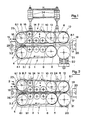
- the stationary belt drive 1 has a toothed belt 3, a driven deflection roller 4, a deflection roller 5 and, for example, three pressure rollers 6.
- the deflection roller 5 and the pressure rollers 6 do not have the same diameter, but are arranged so that they form a drive surface 3.1 lying in one plane together with the toothed belt 3.
- the axis 4.1 of the driven deflection roller 4 is mounted relative to the pressure rollers 6 in such a way that the toothed belt 3 runs into the drive surface 3.1 with an inclination 3.2.
- a gear 7 is arranged on the same axis 4.1.
- a displaceably mounted belt drive 2 is provided, consisting of a toothed belt 8, a driven deflection roller 9 rotatably mounted on a fixed axis 9.1, and a displaceably mounted support plate 10.
- the fixed axis 9.1 always has a constant center distance Axis 4.1 of the stationary Belt drive 1 and additionally carries a gear 23 driving the deflection roller 9, which meshes with the gear 7 driving the stationary belt drive 1.
- the slidably mounted support plate 10 of the slidably mounted belt drive 2 is, for example, slidably guided on two guide pins 11 arranged perpendicular to the drive surface 3.1.
- the support plate 10 receives a deflection roller 12, a pressure roller 13, for example three smaller pressure rollers 14 and a compensating roller 15.
- the deflection roller 12 and the pressure rollers 13, 14 are arranged on the support plate 10 in such a way that, together with the toothed belt 8, they always form a drive surface 8.1 lying in one plane and running parallel to the drive surface 3.1 of the fixed belt drive 1.
- the support plate 10 can be moved against the stationary belt drive 1 with the aid of a drive unit, for example two pneumatic piston-cylinder units 24, the drive surface 8.1 of the slidably mounted belt drive 2 being pressed against the drive surface 3.1 of the stationary belt drive 1.
- the compensating roller 15 serves to keep the toothed belt 8 of the slidably mounted belt drive 2 under tension in the extended rest position, or a length reserve of the toothed belt 8, which is used for the displacement of the support plate 10 with the tensioning rollers 13, 14 and the deflection roller 12 into the working position is needed to record in the extended rest position.
- a wire or cable 18 is inserted between the drive surfaces 3.1, 8.1 of the two toothed belts 3, 8 rolling on one another.
- the pressure rollers 6 and the deflection roller 5 of the stationary belt drive 1 lie in a roller-like manner with respect to the pressure rollers 14, 13 of the displaceably mounted belt drive 2, so that the wire or the cable 18 is also moved through the two strands of the counter-driven belt drives 1, 2 which are moved in the same direction .
- the cable 18 is clamped by a clamping and tensioning device 19 mounted in the axial direction of the supplied cable 18 and on the Cable exit side 17 passed through a clamping device 20.
- a cable processing machine (not shown) with, for example, a cutting and stripping device and possibly a crimping press is arranged.
- the drive surface 8.1 of the slidably mounted belt drive 2 projects beyond the drive surface 3.1 of the stationary belt drive 1 on the cable outlet side 17 with the aid of the deflection roller 12.
- a drive roller 21 is opposite the deflection roller 12
- Cable length measuring device 22 is arranged, which is equipped with an adjustable infeed, which enables the driving roller 21 to rotate with the moving cable 18, but prevents rotation with a missing cable 18 through the toothed belt 8 of the displaceably mounted belt drive 2.
- the device described above for feeding an electrical conductor or a cable 18 into an automatic cable processing machine works as follows: A selected cable 18 is manually moved out of the belt drives 1, 2 when the toothed belt 3, 8 is not driven by the clamping tensioning device 19, passed between the toothed belts 3, 8 of the two belt drives 1, 2 and through the clamping device 20.
- the cable is clamped by the clamping tensioning device 19 and by the clamping device 20, tensioned with the clamping tensioning device and the displaceably mounted belt drive 2, for example with the aid of the two pneumatic piston-cylinder units 24, until the retracted cable 18 between the two drive surfaces 3.1 , 8.1 of the belt drives 1, 2 is held.
- the slidably mounted support plate 10 of the slidable belt drive 2 is guided together with the pressure rollers 13, 14, the pinch roller 12 and the compensating roller 15, guided in parallel by the two guide pins 11, against the stationary belt drive 1, while the driven deflection roller 9 of the slidable belt drive 2 their location maintains.
- the support plate 10 is guided by the guide pin 11 in such a way that the drive surface 8.1 of the toothed belt 8 that is formed moves in parallel against the drive surface 3.1 of the toothed belt 3 of the stationary belt drive 1.
- a stationary, tapered guide bush 25 guides the cable 18 exactly between the drive surfaces 3.1, 8.1 of the belt drives 1, 2.
- the compensating roller 15 causes the displaceable belt drive to have approximately the same belt tension in any position between the extended rest position (FIG. 1) and the retracted working position (FIG. 2) despite the stationary, driven deflection roller 9.
- Both toothed belts 3.8 can additionally be tensioned by a tensioning device, not shown. Due to the drive surface 8.1 of the displaceable belt drive 2 projecting beyond the drive surface 3.1 of the stationary belt drive 1, the surface of the drive roller 2 of the cable length measuring device 22 also comes into contact with the clamped cable 18.
- the drive roller 21 of the cable length measuring device 22 can execute a limited path perpendicular to the direction of movement of the cable 18 and is pressed against the cable 18 by the force of springs and later driven by the moving cable 18.
- the clamping device 20 and the clamping tensioning device 19 are now released and at the same time the drive for the belt drives is switched on, which, via the toothed wheels 7, 23, both belt drives 1, 2 simultaneously and with the same Drives speed.
- the cable 18 is moved forward and the cable end is passed through the cutting device (not shown), stopped and a first cut is made, the end of the cable is stripped and provided with a crimp contact.
- the cable length measuring device is given a certain cable length.
- the cable feeder is now ready for automatic operation, in which the two driven belt drives move the cable forward.
- the cable in turn drives the drive roller of the cable length measuring device until the predetermined cable length is reached and the length measuring device gives the impulse to stop the belt drives and the control program for holding the cable in the cutting device, for actuating the cutting knife of the stripping device, the crimping press, etc. and used to repeat the process described.
- the stationary belt drive has four rollers arranged in one plane and the displaceable belt drive has five rollers arranged in one plane, each of which, together with the associated toothed belt, has two opposing drive surfaces form. It is readily conceivable that fewer or more rollers can also be used to form such drive surfaces, but it must be ensured that one roller of the stationary belt drive always works together with an opposite roller of the displaceable belt drive, and that the displaceable belt drive is in one drive plane always has one roll more than the fixed belt drive, which creates a drive surface which projects beyond the drive surface of the fixed belt drive and on which the driving roller of the cable length measuring device is driven with the aid of the moving cable.
- Two identical, commercially available toothed belts are provided for the two belt drives described. But it is easily conceivable two timing belts with different To provide surface hardness for a softer and a harder drive surface or to equip one belt drive with a double toothed belt and the second with a normal toothed belt.
Landscapes
- Engineering & Computer Science (AREA)
- Manufacturing & Machinery (AREA)
- Forwarding And Storing Of Filamentary Material (AREA)
- Wire Processing (AREA)
Applications Claiming Priority (2)
| Application Number | Priority Date | Filing Date | Title |
|---|---|---|---|
| CH378689 | 1989-10-18 | ||
| CH3786/89 | 1989-10-18 |
Publications (2)
| Publication Number | Publication Date |
|---|---|
| EP0423443A1 true EP0423443A1 (fr) | 1991-04-24 |
| EP0423443B1 EP0423443B1 (fr) | 1994-09-28 |
Family
ID=4263451
Family Applications (1)
| Application Number | Title | Priority Date | Filing Date |
|---|---|---|---|
| EP90114421A Expired - Lifetime EP0423443B1 (fr) | 1989-10-18 | 1990-07-27 | Procédé et dispositif de réalisation du procédé pour l'alimentation d'un câble dans un automate pour façonner des câbles |
Country Status (4)
| Country | Link |
|---|---|
| US (1) | US5109598A (fr) |
| EP (1) | EP0423443B1 (fr) |
| JP (1) | JP2904440B2 (fr) |
| DE (1) | DE59007328D1 (fr) |
Cited By (16)
| Publication number | Priority date | Publication date | Assignee | Title |
|---|---|---|---|---|
| US5235735A (en) * | 1991-04-17 | 1993-08-17 | Ttc Technology Trading Company | Apparatus for cutting and insulation stripping of an electrical cable |
| US5368212A (en) * | 1991-01-21 | 1994-11-29 | Ttc Technology Trading Company | Apparatus for infeeding a cable to an automatic cable processing machine |
| EP0707365A1 (fr) * | 1990-11-09 | 1996-04-17 | Eubanks Engineering Company | Appareil pour dénuder à lames multiples pour câble et fil métallique |
| US5515602A (en) * | 1990-11-09 | 1996-05-14 | Eubanks Engineering Company | Multiple blade set strip apparatus for cable and wire |
| US5517882A (en) * | 1990-11-09 | 1996-05-21 | Eubanks Engineering Company | Wire and cable cutting and stripping using slidable interfitting blades with complementary configurations |
| EP0655812A3 (fr) * | 1993-11-30 | 1997-02-05 | Molex Inc | Dispositif d'alimentation des fils multiples. |
| WO1997017751A1 (fr) * | 1995-11-06 | 1997-05-15 | Schleuniger Holding Ag | Dispositif de denudage |
| US5630341A (en) * | 1990-11-09 | 1997-05-20 | Eubanks Engineering Co. | Method for processing cable and wire |
| US5653016A (en) * | 1990-11-09 | 1997-08-05 | Eubanks Engineering Company | Wire and cable drive apparatus in wire and cable cutting and stripping system |
| US6272740B1 (en) | 1990-11-09 | 2001-08-14 | Eubanks Engineering Co. | Wire and cable cutting and stripping using endless belt conveyors |
| WO2002057169A1 (fr) * | 2001-01-19 | 2002-07-25 | Maillefer S.A. | Agencement pour dispositif d'entrainement de bande sans fin |
| US6910256B2 (en) * | 1995-11-06 | 2005-06-28 | Schleuniger Holding Ag | Continuous cable processing apparatus |
| CN109160368A (zh) * | 2018-09-12 | 2019-01-08 | 徐州领君仁驰自动化设备有限公司 | 一种剥线机多轮简易变速箱 |
| EP3544131A1 (fr) | 2018-03-23 | 2019-09-25 | Komax Holding Ag | Machine de traitement de câbles dotée des éléments de guidage pouvant se déplacer et procédé d'insertion d'un câble dans une machine de traitement de câbles |
| CN113353721A (zh) * | 2021-06-28 | 2021-09-07 | 湖南天剑海洋工程设备有限公司 | 一种线缆牵引装置及其夹持机构 |
| US20240286864A1 (en) * | 2023-02-28 | 2024-08-29 | The Boeing Company | On-Pallet Dual-Belt Mechanism Driven by Off-Pallet Motor for Cable Handling at Processing Module |
Families Citing this family (29)
| Publication number | Priority date | Publication date | Assignee | Title |
|---|---|---|---|---|
| US5469763A (en) * | 1990-11-09 | 1995-11-28 | Eubanks Engineering Company | Wire and cable processing system |
| US5528962A (en) * | 1990-11-09 | 1996-06-25 | Eubanks Engineering Company | Multiple blade set strip apparatus for cable and wire |
| US5343605A (en) * | 1991-09-26 | 1994-09-06 | Eubanks Engineering Company | Wire marking, cutting and stripping apparatus and method |
| US5317812A (en) * | 1992-03-06 | 1994-06-07 | Artos Engineering | Wire feeding and measuring apparatus |
| US5681131A (en) * | 1995-07-18 | 1997-10-28 | The Consumers' Gas Company Ltd. | Cable feeding system and umbilical cable therefor |
| US5809849A (en) * | 1996-02-08 | 1998-09-22 | Coffey; Kevin M. | Machine for stripping insulation from wire |
| JP4085185B2 (ja) * | 1997-02-14 | 2008-05-14 | モレックス インコーポレーテッド | マルチ電気ハーネス製造装置に於ける電線測長装置 |
| US6073916A (en) * | 1998-10-08 | 2000-06-13 | Greenlee Textron Inc. | Powered cable feeding system |
| SE516117C2 (sv) * | 1999-05-27 | 2001-11-19 | Abb Ab | Utrustning och förfarande för att åstadkomma och framställa en lindning av elektrisk kabel i en elektrisk maskin |
| US8161786B2 (en) * | 2008-04-15 | 2012-04-24 | Glen Stapleton | Apparatus for feeding and turning tube products into a pilger mill machine |
| GB0817639D0 (en) | 2008-09-26 | 2008-11-05 | British Telecomm | Cable installation apparatus |
| EP2230545A1 (fr) | 2009-03-19 | 2010-09-22 | BRITISH TELECOMMUNICATIONS public limited company | Détection passive à distance de courant d'air et de câble |
| GB0905590D0 (en) * | 2009-03-31 | 2009-05-13 | British Telecomm | Blown cable apparatus |
| CN102195226B (zh) * | 2010-03-12 | 2014-09-03 | 库迈思控股股份公司 | 线缆供给和旋转系统 |
| EP2369388A1 (fr) | 2010-03-26 | 2011-09-28 | British Telecommunications public limited company | Plateau porte-épissures de fibres optiques |
| CN102446589B (zh) * | 2011-08-31 | 2013-07-03 | 白城福佳机械制造有限公司 | 包带牵引机 |
| WO2015008923A1 (fr) * | 2013-07-16 | 2015-01-22 | 대우조선해양 주식회사 | Dispositif de préhension pour réaliser une pose de fil |
| CN104112546A (zh) * | 2014-07-08 | 2014-10-22 | 平湖迪工机械制造有限公司 | 一种成缆机 |
| CN104692185A (zh) * | 2015-01-09 | 2015-06-10 | 芜湖航天特种电缆厂 | 牵引机 |
| DK3101746T3 (en) * | 2015-06-03 | 2019-03-18 | As P K Jeppesen Og Soen Næstved | A cable feed module for feeding cables or pipes |
| CN105119129A (zh) * | 2015-08-31 | 2015-12-02 | 芜湖顺成电子有限公司 | 电线剥线装置 |
| CN109311064A (zh) * | 2016-05-05 | 2019-02-05 | 石器时代股份公司 | 环形带柔性管清洁喷枪驱动设备 |
| CN106602383A (zh) * | 2016-12-31 | 2017-04-26 | 东莞市贺众精密机械有限公司 | 一种具有两芯线分线功能的端子机 |
| CN108584534A (zh) * | 2018-06-01 | 2018-09-28 | 嘉兴市华益股份有限公司 | 一种混纺纱连续收卷机构 |
| KR102677254B1 (ko) * | 2018-10-31 | 2024-06-21 | 쉴로이니게르 아게 | 케이블 처리 기계용 얼라이닝 장치 및 얼라이닝 시스템 운영 방법 |
| CN112660928B (zh) * | 2021-03-16 | 2022-01-21 | 国网山东省电力公司安丘市供电公司 | 一种电动线缆放线装置 |
| CN113602899B (zh) * | 2021-07-15 | 2023-01-10 | 蓝德能源科技股份有限公司 | 一种无损式电缆加工用牵引机构及方法 |
| CN115649964A (zh) * | 2022-10-24 | 2023-01-31 | 中国通信建设第四工程局有限公司 | 一种光缆铺设牵引装置 |
| CN117361220A (zh) * | 2023-11-17 | 2024-01-09 | 苏州华诺志恒智能科技有限公司 | 一种线缆定长送料机构 |
Citations (3)
| Publication number | Priority date | Publication date | Assignee | Title |
|---|---|---|---|---|
| DE2047460A1 (de) * | 1969-09-29 | 1971-04-15 | Gen Electric | Drahtschneid und abisohervor richtung |
| GB2077518A (en) * | 1980-05-30 | 1981-12-16 | Yazaki Corp | Method and apparatus for processing insulated wide |
| EP0185788A1 (fr) * | 1984-12-21 | 1986-07-02 | Audi Ag | Dispositif d'alimentation en fil pour une machine à couper et dénuder les fils conducteurs isolés |
Family Cites Families (6)
| Publication number | Priority date | Publication date | Assignee | Title |
|---|---|---|---|---|
| US3368428A (en) * | 1966-09-12 | 1968-02-13 | Artos Engineering Co | Wire cutting and stripping machine |
| US3874076A (en) * | 1971-03-26 | 1975-04-01 | Sumitomo Electric Industries | Method and apparatus for manufacturing soft metal sheaths for electrical wires |
| US4043362A (en) * | 1976-02-09 | 1977-08-23 | Gardner-Denver Company | Cutting and insulation stripping apparatus for twisted wire pair |
| US4179056A (en) * | 1976-08-16 | 1979-12-18 | Chemetron Corporation | Wire-feeding mechanism |
| US4521946A (en) * | 1982-03-31 | 1985-06-11 | Artos Engineering Company | Cutter and belt type conveyor for wire segments |
| DE3643201A1 (de) * | 1986-12-18 | 1988-06-30 | Statomat Globe Maschf | Verfahren und vorrichtung zum ablaengen von kabeln von einem kabelvorrat zur bearbeitung der kabelenden |
-
1990
- 1990-07-27 DE DE59007328T patent/DE59007328D1/de not_active Expired - Fee Related
- 1990-07-27 EP EP90114421A patent/EP0423443B1/fr not_active Expired - Lifetime
- 1990-08-22 US US07/571,325 patent/US5109598A/en not_active Expired - Lifetime
- 1990-09-26 JP JP2256778A patent/JP2904440B2/ja not_active Expired - Fee Related
Patent Citations (3)
| Publication number | Priority date | Publication date | Assignee | Title |
|---|---|---|---|---|
| DE2047460A1 (de) * | 1969-09-29 | 1971-04-15 | Gen Electric | Drahtschneid und abisohervor richtung |
| GB2077518A (en) * | 1980-05-30 | 1981-12-16 | Yazaki Corp | Method and apparatus for processing insulated wide |
| EP0185788A1 (fr) * | 1984-12-21 | 1986-07-02 | Audi Ag | Dispositif d'alimentation en fil pour une machine à couper et dénuder les fils conducteurs isolés |
Cited By (20)
| Publication number | Priority date | Publication date | Assignee | Title |
|---|---|---|---|---|
| US6272740B1 (en) | 1990-11-09 | 2001-08-14 | Eubanks Engineering Co. | Wire and cable cutting and stripping using endless belt conveyors |
| EP0707365A1 (fr) * | 1990-11-09 | 1996-04-17 | Eubanks Engineering Company | Appareil pour dénuder à lames multiples pour câble et fil métallique |
| US5515602A (en) * | 1990-11-09 | 1996-05-14 | Eubanks Engineering Company | Multiple blade set strip apparatus for cable and wire |
| US5517882A (en) * | 1990-11-09 | 1996-05-21 | Eubanks Engineering Company | Wire and cable cutting and stripping using slidable interfitting blades with complementary configurations |
| US5630341A (en) * | 1990-11-09 | 1997-05-20 | Eubanks Engineering Co. | Method for processing cable and wire |
| US5653016A (en) * | 1990-11-09 | 1997-08-05 | Eubanks Engineering Company | Wire and cable drive apparatus in wire and cable cutting and stripping system |
| US5368212A (en) * | 1991-01-21 | 1994-11-29 | Ttc Technology Trading Company | Apparatus for infeeding a cable to an automatic cable processing machine |
| US5235735A (en) * | 1991-04-17 | 1993-08-17 | Ttc Technology Trading Company | Apparatus for cutting and insulation stripping of an electrical cable |
| EP0655812A3 (fr) * | 1993-11-30 | 1997-02-05 | Molex Inc | Dispositif d'alimentation des fils multiples. |
| WO1997017751A1 (fr) * | 1995-11-06 | 1997-05-15 | Schleuniger Holding Ag | Dispositif de denudage |
| US8234772B2 (en) | 1995-11-06 | 2012-08-07 | Schleuniger Holding Ag | Continuous cable processing apparatus |
| EP1271729A3 (fr) * | 1995-11-06 | 2003-08-06 | Schleuniger Holding AG | Dispositif de dénudage |
| US6910256B2 (en) * | 1995-11-06 | 2005-06-28 | Schleuniger Holding Ag | Continuous cable processing apparatus |
| WO2002057169A1 (fr) * | 2001-01-19 | 2002-07-25 | Maillefer S.A. | Agencement pour dispositif d'entrainement de bande sans fin |
| US7293682B2 (en) | 2001-01-19 | 2007-11-13 | Maillefer S.A. | Arrangement for belt drive device |
| EP3544131A1 (fr) | 2018-03-23 | 2019-09-25 | Komax Holding Ag | Machine de traitement de câbles dotée des éléments de guidage pouvant se déplacer et procédé d'insertion d'un câble dans une machine de traitement de câbles |
| US10974924B2 (en) | 2018-03-23 | 2021-04-13 | Komax Holding Ag | Cable processing machine with movable guide elements and method for laying a cable in a cable processing machine |
| CN109160368A (zh) * | 2018-09-12 | 2019-01-08 | 徐州领君仁驰自动化设备有限公司 | 一种剥线机多轮简易变速箱 |
| CN113353721A (zh) * | 2021-06-28 | 2021-09-07 | 湖南天剑海洋工程设备有限公司 | 一种线缆牵引装置及其夹持机构 |
| US20240286864A1 (en) * | 2023-02-28 | 2024-08-29 | The Boeing Company | On-Pallet Dual-Belt Mechanism Driven by Off-Pallet Motor for Cable Handling at Processing Module |
Also Published As
| Publication number | Publication date |
|---|---|
| US5109598A (en) | 1992-05-05 |
| DE59007328D1 (de) | 1994-11-03 |
| EP0423443B1 (fr) | 1994-09-28 |
| JPH03179616A (ja) | 1991-08-05 |
| JP2904440B2 (ja) | 1999-06-14 |
Similar Documents
| Publication | Publication Date | Title |
|---|---|---|
| EP0423443B1 (fr) | Procédé et dispositif de réalisation du procédé pour l'alimentation d'un câble dans un automate pour façonner des câbles | |
| EP0496049B1 (fr) | Perfectionnement au dispositif pour l'alimentation d'un câble dans un automate pour façonner des câbles | |
| EP0185788B1 (fr) | Dispositif d'alimentation en fil pour une machine à couper et dénuder les fils conducteurs isolés | |
| DE69206181T2 (de) | Kabelführungs- und Vorbereitungsvorrichtung. | |
| EP0598276B1 (fr) | Dispositif d'amenée et de changement de câble pour machine de traitement de câble | |
| DE3338915C2 (fr) | ||
| AT518608B1 (de) | Kantenanleimvorrichtung | |
| DE2548771B2 (de) | Vorschub- und Spanneinrichtung für eine Trennmaschine | |
| EP0161657A2 (fr) | Dispositif pour guider une électrode à découper filiforme ou en ruban dans une machine-outil | |
| DE4019285A1 (de) | Spanneinrichtung zum gezielten spannen von werkstuecken | |
| DE2420690B2 (de) | Vorrichtung zum biegen von rohrabschnitten | |
| DE2647222B2 (de) | Vorrichtung zum Schneiden, Entdrallen und Abisolieren nebeneinanderliegender Bereiche vorgegebener Länge eines isolierten, verdrallten elektrischen Leiterpaares | |
| AT390025B (de) | Vorrichtung zum herstellen prismatischer oder pyramidenstumpffoermiger balken | |
| DE4441301C1 (de) | Vorrichtung zur Herstellung von Brezeln | |
| DE69808879T2 (de) | Vorrichtung zur Reinigung von Draht für die Herstellung von gezogenen Metalldrähten | |
| DE19917028A1 (de) | Raumsparende Drahtziehmaschine mit in Bodenhöhe angeordnetem Drahtbund | |
| EP0576966A2 (fr) | Méthode et dispositif pour couper et dénuder des câbles enrobés | |
| EP0236688A2 (fr) | Procédé pour le changement des conducteurs électriques, lors de leur équipement avec des connecteurs électriques, et dispositif pour la mise en oeuvre du procédé | |
| DE3338096A1 (de) | Verfahren und vorrichtung zum ablaengen von metallenen langformguetern | |
| DE3443754C2 (fr) | ||
| DE2910633A1 (de) | Vorrichtung zum biegen, sicken und ablaengen der anschlussdraehte von elektrischen bauelementen | |
| DE29819851U1 (de) | Seil-Blocksäge für die Bearbeitung von Natur- und Kunststeinblöcken | |
| DE4111431C2 (de) | Verfahren und Vorrichtung zum Herstellen von endlosen Stahlbändern | |
| DE19519395C1 (de) | Verfahren und Vorrichtung zum Ziehen von Stangen | |
| EP1126945B1 (fr) | Dispositif pour cintrer et couper une partie d'extremite d'un cordon de matiere |
Legal Events
| Date | Code | Title | Description |
|---|---|---|---|
| PUAI | Public reference made under article 153(3) epc to a published international application that has entered the european phase |
Free format text: ORIGINAL CODE: 0009012 |
|
| AK | Designated contracting states |
Kind code of ref document: A1 Designated state(s): CH DE FR IT LI |
|
| 17P | Request for examination filed |
Effective date: 19910926 |
|
| 17Q | First examination report despatched |
Effective date: 19930519 |
|
| GRAA | (expected) grant |
Free format text: ORIGINAL CODE: 0009210 |
|
| AK | Designated contracting states |
Kind code of ref document: B1 Designated state(s): CH DE FR IT LI |
|
| REF | Corresponds to: |
Ref document number: 59007328 Country of ref document: DE Date of ref document: 19941103 |
|
| ET | Fr: translation filed | ||
| ITF | It: translation for a ep patent filed | ||
| PLBE | No opposition filed within time limit |
Free format text: ORIGINAL CODE: 0009261 |
|
| STAA | Information on the status of an ep patent application or granted ep patent |
Free format text: STATUS: NO OPPOSITION FILED WITHIN TIME LIMIT |
|
| 26N | No opposition filed | ||
| PGFP | Annual fee paid to national office [announced via postgrant information from national office to epo] |
Ref country code: DE Payment date: 20080722 Year of fee payment: 19 |
|
| PGFP | Annual fee paid to national office [announced via postgrant information from national office to epo] |
Ref country code: IT Payment date: 20080725 Year of fee payment: 19 Ref country code: FR Payment date: 20080715 Year of fee payment: 19 |
|
| PGFP | Annual fee paid to national office [announced via postgrant information from national office to epo] |
Ref country code: CH Payment date: 20091016 Year of fee payment: 20 |
|
| REG | Reference to a national code |
Ref country code: FR Ref legal event code: ST Effective date: 20100331 |
|
| PG25 | Lapsed in a contracting state [announced via postgrant information from national office to epo] |
Ref country code: FR Free format text: LAPSE BECAUSE OF NON-PAYMENT OF DUE FEES Effective date: 20090731 |
|
| PG25 | Lapsed in a contracting state [announced via postgrant information from national office to epo] |
Ref country code: DE Free format text: LAPSE BECAUSE OF NON-PAYMENT OF DUE FEES Effective date: 20100202 |
|
| REG | Reference to a national code |
Ref country code: CH Ref legal event code: PL |
|
| PG25 | Lapsed in a contracting state [announced via postgrant information from national office to epo] |
Ref country code: IT Free format text: LAPSE BECAUSE OF NON-PAYMENT OF DUE FEES Effective date: 20090727 |