EP0423533A2 - Herstellung eines Teilungsträgers aus Kunststoff mit einer Teilungstruktur - Google Patents
Herstellung eines Teilungsträgers aus Kunststoff mit einer Teilungstruktur Download PDFInfo
- Publication number
- EP0423533A2 EP0423533A2 EP90118833A EP90118833A EP0423533A2 EP 0423533 A2 EP0423533 A2 EP 0423533A2 EP 90118833 A EP90118833 A EP 90118833A EP 90118833 A EP90118833 A EP 90118833A EP 0423533 A2 EP0423533 A2 EP 0423533A2
- Authority
- EP
- European Patent Office
- Prior art keywords
- graduation
- graduation carrier
- division
- carrier
- carrier according
- Prior art date
- Legal status (The legal status is an assumption and is not a legal conclusion. Google has not performed a legal analysis and makes no representation as to the accuracy of the status listed.)
- Granted
Links
- 229920003023 plastic Polymers 0.000 title claims abstract description 27
- 238000004519 manufacturing process Methods 0.000 title claims description 15
- 241000446313 Lamella Species 0.000 claims abstract description 8
- 238000005266 casting Methods 0.000 claims abstract description 8
- 238000001746 injection moulding Methods 0.000 claims description 2
- 238000000034 method Methods 0.000 claims 1
- 229910000831 Steel Inorganic materials 0.000 description 4
- 239000010959 steel Substances 0.000 description 4
- 238000004512 die casting Methods 0.000 description 3
- 239000007788 liquid Substances 0.000 description 3
- 239000002184 metal Substances 0.000 description 2
- 229910052751 metal Inorganic materials 0.000 description 2
- 238000010521 absorption reaction Methods 0.000 description 1
- 238000004026 adhesive bonding Methods 0.000 description 1
- 238000010276 construction Methods 0.000 description 1
- 238000001816 cooling Methods 0.000 description 1
- 238000011161 development Methods 0.000 description 1
- 230000018109 developmental process Effects 0.000 description 1
- 239000010931 gold Substances 0.000 description 1
- 229910052737 gold Inorganic materials 0.000 description 1
- 230000010354 integration Effects 0.000 description 1
- 229910052759 nickel Inorganic materials 0.000 description 1
- 150000002815 nickel Chemical class 0.000 description 1
- PXHVJJICTQNCMI-UHFFFAOYSA-N nickel Substances [Ni] PXHVJJICTQNCMI-UHFFFAOYSA-N 0.000 description 1
- 230000003287 optical effect Effects 0.000 description 1
- 238000005192 partition Methods 0.000 description 1
- 238000002310 reflectometry Methods 0.000 description 1
Images

Classifications
-
- G—PHYSICS
- G01—MEASURING; TESTING
- G01D—MEASURING NOT SPECIALLY ADAPTED FOR A SPECIFIC VARIABLE; ARRANGEMENTS FOR MEASURING TWO OR MORE VARIABLES NOT COVERED IN A SINGLE OTHER SUBCLASS; TARIFF METERING APPARATUS; MEASURING OR TESTING NOT OTHERWISE PROVIDED FOR
- G01D5/00—Mechanical means for transferring the output of a sensing member; Means for converting the output of a sensing member to another variable where the form or nature of the sensing member does not constrain the means for converting; Transducers not specially adapted for a specific variable
- G01D5/26—Mechanical means for transferring the output of a sensing member; Means for converting the output of a sensing member to another variable where the form or nature of the sensing member does not constrain the means for converting; Transducers not specially adapted for a specific variable characterised by optical transfer means, i.e. using infrared, visible, or ultraviolet light
- G01D5/32—Mechanical means for transferring the output of a sensing member; Means for converting the output of a sensing member to another variable where the form or nature of the sensing member does not constrain the means for converting; Transducers not specially adapted for a specific variable characterised by optical transfer means, i.e. using infrared, visible, or ultraviolet light with attenuation or whole or partial obturation of beams of light
- G01D5/34—Mechanical means for transferring the output of a sensing member; Means for converting the output of a sensing member to another variable where the form or nature of the sensing member does not constrain the means for converting; Transducers not specially adapted for a specific variable characterised by optical transfer means, i.e. using infrared, visible, or ultraviolet light with attenuation or whole or partial obturation of beams of light the beams of light being detected by photocells
- G01D5/347—Mechanical means for transferring the output of a sensing member; Means for converting the output of a sensing member to another variable where the form or nature of the sensing member does not constrain the means for converting; Transducers not specially adapted for a specific variable characterised by optical transfer means, i.e. using infrared, visible, or ultraviolet light with attenuation or whole or partial obturation of beams of light the beams of light being detected by photocells using displacement encoding scales
- G01D5/34707—Scales; Discs, e.g. fixation, fabrication, compensation
Definitions
- the invention relates to a graduation carrier made of plastic with a graduation structure, in particular for a photoelectric position measuring device.
- Such a position measuring device is used to measure the relative position of two mutually movable objects, for example two machine parts of a machine tool for positioning a tool with respect to a workpiece to be machined.
- one object is connected to the graduation carrier, the graduation structure of which is scanned by a scanning unit connected to the other object.
- a circular graduation carrier made of plastic with a hub for an angle measuring device, on which a dividing structure in the form of a metal disk provided with cutouts in the center region is concentric is fixed by gluing; in the outer area with the recesses, the graduation carrier and the metal disk are spaced apart.
- This graduation carrier with the only rough graduation structure is relatively complex to construct and manufacture.
- the invention has for its object to significantly simplify the structure and manufacture of a division carrier made of plastic with a division structure.
- the advantages achieved by the invention are, in particular, that the form-fitting integration of the dividing structure in the dividing support made of plastic significantly simplifies the construction and manufacture in the casting process or in the injection molding process and thus makes it less expensive.
- a particularly economical production results from the use of molds with multiple uses.
- the optical properties (absorption, reflectivity) of the graduation structure can be varied in many ways. Depending on the embodiment, division structures with a resolution down to the submicron range can be produced.
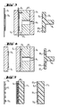
- a first circular graduation carrier TT1 made of plastic with a cast-on hollow hub N1 is shown in cross section, which is shown in Figure 1b in a plan view.
- a division structure TS1 is integrated as a separately prefabricated lamella in the first division carrier TT1, the free surface OT1 of the first division carrier TT1 and the free surface OS1 of the division structure TS1 lying in one plane.
- the division structure TS1 has an incremental or absolute division T1, which in a known manner from translucent Graduation marks and opaque graduation marks exist.
- the first division carrier TT 1 with the division structure TS 1 is used, for example, in a photoelectric angle measuring device for measuring the relative position of two objects which can be displaced relative to one another, for example a carriage with respect to the bed of a processing machine, not shown.
- the hollow hub N1 of the first division carrier TT1 is connected to an adjusting spindle for the slide and a scanning unit, not shown, connected to the bed of the angle measuring device scans the incident or transmitted light, the incremental or absolute division T1 to obtain measured values for the relative position of the two Objects.
- An optically effective structure for example in the form of a Fresnel zone ring F, can be provided on the surface of the transparent graduation carrier TT 2 opposite the incremental graduation T 1.
- a toothing ZN on the hub N 1 and a toothing ZP on the periphery of the first graduation carrier TT 1 are provided as further functional elements.
- FIG 2 the manufacturing phases of a second circular division carrier TT2 made of plastic with a division structure TS2 are shown in cross section from left to right.
- the separately prefabricated slat structure TS2 in the form of a form-etched part with a centering hole B2 (left) is centered on a base plate G2 of a casting mold GF2 by means of a centering pin ZZ2.
- a sprue hole A2 in Lid D2 of the casting mold GF2 is fed to the liquid transparent plastic for die casting (center).
- the base plate G2 is removed and the finished division carrier TT2 made of plastic with the division structure TS2 and a cast-on hub N2 is removed (right).
- the division structure TS2 is form-fitting and positionally integrated in the division carrier TT1, the surface OS2 of the division structure TS2 and the surface OT2 of the division carrier TT2 lying in one plane.
- FIG 3 the manufacturing phases of a third circular division carrier TT3 made of plastic with a division structure TS3 are shown in cross section from left to right.
- the separately prefabricated dividing structure TS3 in the form of a nickel galvanoplastic (left) on a steel sheet S3 as a lamella is arranged centered on a base plate G3 of a mold GF3; centering takes place in a manner not shown outside the mold GF3.
- a sprue hole A3 in the cover D3 of the mold GF3 the liquid transparent plastic for die casting is supplied (center).
- the base plate G3 is removed and the finished division carrier TT3 made of plastic with the division structure TS3 and a molded hub N3 removed; then the steel sheet S3 is removed (right).
- the division structure TS3 is form-fitting and positionally integrated in the division carrier TT3, the surface OS3 of the division structure TS3 and the surface OT3 of the division carrier TT3 lying in one plane.
- FIG Carrier TT4 made of plastic with a division structure TS4 shown in cross section.
- a partition structure TS4 in the form of a gold galvanoplastic is prefabricated separately as a lamella (left).
- the base plate G4 is attached to the mold GF patii, the division structure TS4 occupying a centered position.
- the liquid transparent plastic for the die casting is fed through a sprue hole Auß in the cover D4 of the GFuß mold (center).
- the base plate G4 is removed and the finished division carrier TT4 made of plastic with the division structure TS4 and a cast-on hub N4 is pulled off the base plate G4 (right).
- the division structure TS4 is positively and positionally integrated in the division carrier TT4, the surface OS4 of the division structure TS4 and the surface OT4 of the division carrier TT4 lying in one plane.
- FIG. 5 the manufacturing phases of a fifth rod-shaped graduation carrier TT5 made of plastic with a graduation structure TS5 are shown in cross-section from left to right.
- a dividing structure TS5 with a division T5 as a lamella is prefabricated separately on a steel sheet S5 (left).
- a hardenable plastic layer KS5 and then the division structure TS5 are applied to one surface of the pre-formed division carrier TT5 made of plastic (center). After the plastic layer KS5 has hardened in a printing form (not shown), the steel sheet S5 is pulled off (right).
- the division structure TS5 with a division T5 is positively and positionally integrated in the division carrier TT5, the surface OS5 of the division structure TS5 and the surface OT5 of the division carrier TT5 lie in one plane. After curing, there is no longer an interface between the plastic layer KS5 and the graduation carrier TT5.
- This rod-shaped graduation carrier TT5 with the graduation structure TS5 is used in a length measuring device, not shown.
- the division structure TS can also consist of a stamped part or a part perforated by means of a laser beam.
Landscapes
- Physics & Mathematics (AREA)
- General Physics & Mathematics (AREA)
- Optical Transform (AREA)
- Motor Or Generator Frames (AREA)
- Moulds For Moulding Plastics Or The Like (AREA)
- A Measuring Device Byusing Mechanical Method (AREA)
- Injection Moulding Of Plastics Or The Like (AREA)
- Length-Measuring Instruments Using Mechanical Means (AREA)
Abstract
Description
- Die Erfindung betrifft einen Teilungsträger aus Kunststoff mit einer Teilungsstruktur, insbesondere für eine lichtelektrische Positionsmeßeinrichtung.
- Eine derartige Positionsmeßeinrichtung dient zum Messen der Relativlage zweier zueinander beweglicher Objekte, beispielsweise zweier Maschinenteile einer werkzeugmaschine zum Positionieren eines Werkzeugs bezüglich eines zu bearbeitenden Werkstücks. Zu diesem Zweck ist das eine Objekt mit dem Teilungsträger verbunden, dessen Teilungsstruktur von einer mit dem anderen Objekt verbundenen Abtasteinheit abgetastet wird.
- Aus der US-PS 4,806,751 ist für eine Winkelmeßeinrichtung ein kreisförmiger Teilungstrager aus Kunststoff mit einer Nabe bekannt, auf dem konzentrisch eine Teilungsstruktur in Form einer mit Aussparungen versehenen Metallscheibe im Mittenbereich durch Kleben befestigt ist; im Außenbereich mit den Aussparungen sind der Teilungsträger und die Metallscheibe voneinander beabstandet. Dieser Teilungsträger mit der nur groben Teilungsstruktur ist im Aufbau und in der Herstellung relativ aufwendig.
- Der Erfindung liegt die Aufgabe zugrunde, bei einem Teilungsträger aus Kunststoff mit einer Teilungsstruktur deren Aufbau und Herstellung wesentlich zu vereinfachen.
- Diese Aufgabe wird erfindungsgemäß durch die kennzeichnenden Merkmale des Anspruchs 1 gelöst.
- Die mit der Erfindung erzielten Vorteile bestehen insbesondere darin, daß durch die formschlüssige Integration der Teilungsstruktur im Teilungsträger aus Kunststoff der Aufbau und die Herstellung im Gußverfahren oder im Spritzgußverfahren wesentlich vereinfacht und damit verbilligt werden. Eine besonders wirtschaftliche Herstellung ergibt sich durch die Verwendung von Gußformen mit Mehrfachnutzen. Die optischen Eigenschaften (Absorption, Reflektivität) der Teilungsstruktur sind vielfältig variierbar. Es lassen sich je nach der Ausführungsform Teilungsstrukturen mit einer Auflösung bis zum Submikron-Bereich herstellen.
- Vorteilhafte Ausbildungen der Erfindung entnimmt man den Unteransprüchen.
- Ausführungsbeispiele der Erfindung werden anhand der Zeichnung näher erläutert.
- Es zeigen
- Figur 1a einen ersten Teilungsträger mit einer Teilungsstruktur im Querschnitt und
- Figur 1b in einer Draufsicht;
- Figur 2 die Herstellungsphasen eines zweiten Teilungsträgers mit einer Teilungsstruktur;
- Figur 3 die Herstellungsphasen eines dritten Teilungsträgers mit einer Teilungsstruktur;
- Figur 4 die Herstellungsphasen eines vierten Teilungsträgers mit einer Teilungsstruktur;
- Figur 5 die Herstellungsphasen eines fünften Teilungsträgers mit einer Teilungsstruktur.
- In Figur 1a ist im Querschnitt ein erster kreisförmiger Teilungsträger TT₁ aus Kunststoff mit einer angegossenen Hohlnabe N₁ gezeigt, der in Figur 1b in einer Draufsicht dargestellt ist. Auf der freien Oberfläche OT₁ des ersten Teilungsträgers TT₁ ist eine Teilungsstruktur TS₁ als gesondert vorgefertigte Lamelle formschlüssig im ersten Teilungstrager TT₁ integriert, wobei die freie Oberfläche OT₁ des ersten Teilungsträgers TT₁ und die freie Oberfläche OS₁ der Teilungsstruktur TS₁ in einer Ebene liegen. Die Teilungsstruktur TS₁ weist ,eine inkrementale oder absolute Teilung T₁ auf, die in bekannter Weise aus lichtdurchlässigen Teilungsstrichen und lichtundurchlässigen Teilungsstrichen besteht.
- Der erste Teilungsträger TT₁ mit der Teilungsstruktur TS₁ wird beispielsweise bei einer lichtelektrischen Winkelmeßeinrichtung zur Messung der Relativlage zweier gegeneinander verschiebbarer Objekte, beispielsweise eines Schlittens bezüglich des Bettes einer nicht gezeigten Bearbeitungsmaschine eingesetzt. Zu diesem Zweck ist die Hohlnabe N₁ des ersten Teilungsträgers TT₁ mit einer Verstellspindel für den Schlitten verbunden und eine mit dem Bett verbundene nicht dargestellte Abtasteinheit der Winkelmeßeinrichtung tastet im Auflicht oder im Durchlicht die inkrementale oder absolute Teilung T₁ zur Gewinnung von Meßwerten für die Relatiylage der beiden Objekte ab. Auf der der inkrementalen Teilung T₁ gegenüberliegenden Oberfläche des transparenten Teilungsträgers TT₂ kann eine optisch wirksame Struktur, beispielsweise in Form eines Fresnelschen Zonenringes F, vorgesehen sein. Neben der Nabe N₁ und dem Fresnelschen Zonenring F sind als weitere Funktionselemente eine Verzahnung ZN an der Nabe N₁ und eine Verzahnung ZP an der Peripherie des ersten Teilungsträgers TT₁ vorgesehen.
- In Figur 2 sind von links nach rechts die Herstellungsphasen eines zweiten kreisformigen Teilungsträgers TT₂ aus Kunststoff mit einer Teilungsstruktur TS₂ im Querschnitt gezeigt. Die als Lamelle gesondert vorgefertigte Teilungsstruktur TS₂ in Form eines Formätzteils mit einer Zentrierbohrung B₂ (links) wird auf einer Grundplatte G₂ einer Gußform GF₂ mittels eines Zentrierzapfens ZZ₂ zentriert angeordnet. Durch eine Angußbohrung A₂ im Deckel D₂ der Gußform GF₂ wird der flüssige transparente Kunststoff für den Druckguß zugeführt (Mitte). Nach dem Erkalten des Kunststoffes wird die Grundplatte G₂ entfernt und der fertige Teilungsträger TT₂ aus Kunststoff mit der Teilungsstruktur TS₂ und einer angegossenen Nabe N₂ entnommen (rechts). Die Teilungsstruktur TS₂ ist formschlüssig und lagestabil im Teilungsträger TT₁ integriert, wobei die Oberfläche OS₂ der Teilungsstruktur TS₂ und die Oberfläche OT₂ des Teilungsträgers TT₂ in einer Ebene liegen.
- In Figur 3 sind von links nach rechts die Herstellungsphasen eines dritten kreisförmigen Teilungsträgers TT₃ aus Kunststoff mit einer Teilungsstruktur TS₃ im Querschnitt gezeigt. Die auf einem Stahlblech S₃ als Lamelle gesondert vorgefertigte Teilungsstruktur TS₃ in Form einer Nickel-Galvanoplastik (links) wird auf einer Grundplatte G₃ einer Gußform GF₃ zentriert angeordnet; die Zentrierung erfolgt in nicht gezeigter Weise außerhalb der Gußform GF₃. Durch eine Angußbohrung A₃ im Deckel D₃ der Gußform GF₃ wird der flüssige transparente Kunststoff für den Druckguß zugeführt (Mitte). Nach dem Erkalten des Kunststoffes wird die Grundplatte G₃ entfernt und der fertige Teilungsträger TT₃ aus Kunststoff mit der Teilungsstruktur TS₃ und einer angegossenen Nabe N₃ entnommen; sodann wird das Stahlblech S₃ abgezogen (rechts). Die Teilungsstruktur TS₃ ist formschlüssig und lagestabil im Teilungsträger TT₃ integriert, wobei die Oberfläche OS₃ der Teilungsstruktur TS₃ und die Oberfläche OT₃ des Teilungsträgers TT₃ in einer Ebene liegen.
- In Figur 4 sind von links nach rechts die Herstellungsphasen eines vierten kreisförmigen Teilungs trägers TT₄ aus Kunststoff mit einer Teilungsstruktur TS₄ im Querschnitt gezeigt. Auf einer Grundplatte G₄ einer Gußform GF₄ wird als Lamelle eine Teilungsstruktur TS₄ in Form einer Gold-Galvanoplastik gesondert vorgefertigt (links). Anschließend wird die Grundplatte G₄ an der Gußform GF₄ befestigt, wobei die Teilungsstruktur TS₄ eine zentrierte Lage einnimmt. Durch eine Angußbohrung A₄ im Deckel D₄ der Gußform GF₄ wird der flüssige transparente Kunststoff für den Druckguß zugeführt (Mitte). Nach dem Erkalten des Kunststoffes wird die Grundplatte G₄ entfernt und der fertige Teilungsträger TT₄ aus Kunststoff mit der Teilungsstruktur TS₄ und einer angegossenen Nabe N₄ von der Grundplatte G₄ abgezogen (rechts). Die Teilungsstruktur TS₄ ist formschlüssig und lagestabil im Teilungsträger TT₄ integriert, wobei die Oberfläche OS₄ der Teilungsstruktur TS₄ und die Oberfläche OT₄ des Teilungsträgers TT₄ in einer Ebene liegen.
- In Figur 5 sind von links nach rechts die Herstellungsphasen eines fünften stabförmigen Teilungsträgers TT₅ aus Kunststoff mit einer Teilungsstruktur TS₅ im Querschnitt gezeigt. Auf einem Stahlblech S₅ wird eine Teilungsstruktur TS₅ mit einer Teilung T₅ als Lamelle gesondert vorgefertigt (links). Auf eine Oberfläche des vorgeformten Teilungsträgers TT₅ aus Kunststoff werden eine aushärtbare Kunststof fschicht KS₅ und darauf die Teilungsstruktur TS₅ aufgebracht (Mitte). Nach dem Aushärten der Kunststof fschicht KS₅ in einer nicht gezeigten Druckform wird das Stahlblech S₅ abgezogen (rechts). Die Teilungsstruktur TS₅ mit einer Teilung T₅ ist formschlüssig und lagestabil im Teilungsträger TT₅ integriert, wobei die Oberfläche OS₅ der Teilungsstruktur TS₅ und die Oberfläche OT₅ des Teilungsträgers TT₅ in einer Ebene liegen. Nach dem Aushärten besteht zwischen der Kunststoffschicht KS₅ und dem Teilungsträger TT₅ keine Grenzfläche mehr. Dieser stabformige Teilungsträger TT₅ mit der Teilungsstruktur TS₅ wird in einer nicht gezeigten Längenmeßeinrichtung eingesetzt.
- Die Teilungsstruktur TS kann auch aus einem Stanzteil oder aus einem mittels Laserstrahl schmelzperforierten Teil bestehen.
Claims (11)
Priority Applications (1)
| Application Number | Priority Date | Filing Date | Title |
|---|---|---|---|
| AT90118833T ATE89409T1 (de) | 1989-10-14 | 1990-10-02 | Herstellung eines teilungstraegers aus kunststoff mit einer teilungstruktur. |
Applications Claiming Priority (2)
| Application Number | Priority Date | Filing Date | Title |
|---|---|---|---|
| DE3934339A DE3934339A1 (de) | 1989-10-14 | 1989-10-14 | Teilungstraeger aus kunststoff mit einer teilungsstruktur |
| DE3934339 | 1989-10-14 |
Publications (3)
| Publication Number | Publication Date |
|---|---|
| EP0423533A2 true EP0423533A2 (de) | 1991-04-24 |
| EP0423533A3 EP0423533A3 (en) | 1991-06-26 |
| EP0423533B1 EP0423533B1 (de) | 1993-05-12 |
Family
ID=6391474
Family Applications (1)
| Application Number | Title | Priority Date | Filing Date |
|---|---|---|---|
| EP90118833A Expired - Lifetime EP0423533B1 (de) | 1989-10-14 | 1990-10-02 | Herstellung eines Teilungsträgers aus Kunststoff mit einer Teilungstruktur |
Country Status (5)
| Country | Link |
|---|---|
| US (1) | US5126560A (de) |
| EP (1) | EP0423533B1 (de) |
| JP (1) | JP2610705B2 (de) |
| AT (1) | ATE89409T1 (de) |
| DE (2) | DE3934339A1 (de) |
Cited By (3)
| Publication number | Priority date | Publication date | Assignee | Title |
|---|---|---|---|---|
| FR2676538A1 (fr) * | 1991-05-17 | 1992-11-20 | Telemecanique | Codeur optique rotatif. |
| WO1998021810A1 (de) * | 1996-11-13 | 1998-05-22 | Dr. Johannes Heidenhain Gmbh | Optische positionsmesseinrichtung |
| EP0927873A4 (de) * | 1997-06-23 | 2000-09-27 | Fanuc Ltd | Optische drehkodiereinrichtung |
Families Citing this family (14)
| Publication number | Priority date | Publication date | Assignee | Title |
|---|---|---|---|---|
| DE4338680C1 (de) * | 1993-11-12 | 1995-03-23 | Heidenhain Gmbh Dr Johannes | Längen- oder Winkelmeßeinrichtung |
| US5748181A (en) * | 1994-07-01 | 1998-05-05 | Primax Electronics Ltd. | Cursor controlling apparatus and its direction detection method |
| US5555776A (en) * | 1994-11-21 | 1996-09-17 | International Business Machines Corporation | Cam integrated with a rotation sensor |
| US5701525A (en) * | 1995-12-21 | 1997-12-23 | Polaroid Corporation | Camera encoder assembly, system and method thereof |
| US5786646A (en) * | 1996-10-01 | 1998-07-28 | Emerson Electric Co. | Method and apparatus for aligning a rotor position transducer |
| DE19748292C2 (de) | 1997-10-31 | 2000-03-02 | Zeiss Carl Jena Gmbh | Verfahren zum Anbringen einer Winkelteilung an einer Teilscheibe für Rotationsmeßsysteme |
| US6100519A (en) * | 1998-06-02 | 2000-08-08 | Ching Shun Wang | Photo-detector based calculating means having a grating wheel with integrated lenses |
| JP4240164B2 (ja) * | 1998-07-10 | 2009-03-18 | 株式会社安川電機 | 光学式エンコーダの回転ディスク取付け構造とそれを用いた光学式エンコーダ |
| DE19947161B4 (de) * | 1999-10-01 | 2004-04-08 | Valeo Schalter Und Sensoren Gmbh | Lenkwinkelsensor mit einer Codescheibe |
| JP4726168B2 (ja) * | 2000-04-17 | 2011-07-20 | キヤノン株式会社 | 光学スケール及び光学式エンコーダ |
| DE10036769A1 (de) * | 2000-07-28 | 2002-02-14 | Kostal Leopold Gmbh & Co Kg | Geberscheibe für optoelektronische Drehwinkelsensoren |
| DE10063899B4 (de) * | 2000-12-21 | 2006-01-05 | Sick Stegmann Gmbh | Optisches Winkelmeßsystem |
| US7109614B2 (en) * | 2002-04-29 | 2006-09-19 | Siemens Aktiengesellschaft | Drive unit for determining a rotation position and/or rotation speed of a drive shaft |
| DE102004048317A1 (de) * | 2004-10-05 | 2006-04-06 | Hengstler Gmbh | Codierte Abtastscheibe für einen Drehgeber |
Family Cites Families (14)
| Publication number | Priority date | Publication date | Assignee | Title |
|---|---|---|---|---|
| DE2731201C2 (de) * | 1977-07-11 | 1983-12-08 | Alfred Teves Gmbh, 6000 Frankfurt | Druckmittel-Bremssystem für Motorräder |
| IT1116276B (it) * | 1977-12-30 | 1986-02-10 | Olivetti & Co Spa | Trasduttore di posizione angolare per un organo ruotante |
| US4193199A (en) * | 1978-05-15 | 1980-03-18 | Servo Products Company | Shaft position transducer |
| US4400443A (en) * | 1980-08-18 | 1983-08-23 | Hutchinson Technology Incorporated | Laminated encoder disc |
| JPS5830814U (ja) * | 1981-08-25 | 1983-02-28 | オムロン株式会社 | ロ−タリ−エンコ−ダ |
| JPS6148719A (ja) * | 1984-08-16 | 1986-03-10 | Fanuc Ltd | 光学式ロ−タリ−エンコ−ダ |
| JPS6196410A (ja) * | 1984-10-17 | 1986-05-15 | Asahi Chem Ind Co Ltd | ロ−タリ−エンコ−ダ−用デイスクの製造法 |
| IT1184495B (it) * | 1985-04-26 | 1987-10-28 | Michele Merlo | Codificatore (encoder) ottico incrementale a nonio accordato |
| JPH0421069Y2 (de) * | 1985-09-30 | 1992-05-14 | ||
| NL8502679A (nl) * | 1985-10-01 | 1987-05-04 | Philips Nv | Optisch omzetelement en verplaatsingsmeter voorzien van dit element. |
| US4780610A (en) * | 1986-03-04 | 1988-10-25 | Alps Electric Co., Ltd. | Optical rotary encoder having superposed metal plate and shield plate |
| JPS6437740A (en) * | 1987-07-31 | 1989-02-08 | Mitsui Petrochemical Ind | Manufacture of magnetic hub |
| JPH01210822A (ja) * | 1988-02-18 | 1989-08-24 | Victor Co Of Japan Ltd | ロータリーエンコーダ用ディスク |
| DE3908932A1 (de) * | 1988-05-25 | 1989-12-07 | Heidenhain Gmbh Dr Johannes | Winkelmessvorrichtung |
-
1989
- 1989-10-14 DE DE3934339A patent/DE3934339A1/de active Granted
-
1990
- 1990-10-02 EP EP90118833A patent/EP0423533B1/de not_active Expired - Lifetime
- 1990-10-02 DE DE9090118833T patent/DE59001436D1/de not_active Expired - Fee Related
- 1990-10-02 AT AT90118833T patent/ATE89409T1/de not_active IP Right Cessation
- 1990-10-11 JP JP2270638A patent/JP2610705B2/ja not_active Expired - Fee Related
- 1990-10-12 US US07/596,466 patent/US5126560A/en not_active Expired - Lifetime
Cited By (4)
| Publication number | Priority date | Publication date | Assignee | Title |
|---|---|---|---|---|
| FR2676538A1 (fr) * | 1991-05-17 | 1992-11-20 | Telemecanique | Codeur optique rotatif. |
| WO1998021810A1 (de) * | 1996-11-13 | 1998-05-22 | Dr. Johannes Heidenhain Gmbh | Optische positionsmesseinrichtung |
| EP0927873A4 (de) * | 1997-06-23 | 2000-09-27 | Fanuc Ltd | Optische drehkodiereinrichtung |
| US6255644B1 (en) | 1997-06-23 | 2001-07-03 | Fanuc Ltd. | Optical rotary encoder |
Also Published As
| Publication number | Publication date |
|---|---|
| EP0423533B1 (de) | 1993-05-12 |
| US5126560A (en) | 1992-06-30 |
| JPH03137516A (ja) | 1991-06-12 |
| DE3934339C2 (de) | 1992-10-01 |
| JP2610705B2 (ja) | 1997-05-14 |
| ATE89409T1 (de) | 1993-05-15 |
| DE3934339A1 (de) | 1991-04-25 |
| EP0423533A3 (en) | 1991-06-26 |
| DE59001436D1 (de) | 1993-06-17 |
Similar Documents
| Publication | Publication Date | Title |
|---|---|---|
| EP0423533B1 (de) | Herstellung eines Teilungsträgers aus Kunststoff mit einer Teilungstruktur | |
| DE69317293T2 (de) | Verfahren zum herstellen von plastikformen und verfahren zum giessen von kontaktlinsen | |
| DE3611246C2 (de) | ||
| DE69014942T2 (de) | Brutschrank. | |
| EP0141123B1 (de) | Lichtelektrische inkrementale Messeinrichtung | |
| EP0913669B1 (de) | Verfahren zum Anbringen einer Winkelteilung an einer Teilscheibe für Rotationsmesssysteme | |
| DE19619353A1 (de) | Verfahren zur Herstellung eines integriert optischen Wellenleiterbauteiles sowie Anordnung | |
| EP0978005B1 (de) | Miniaturisiertes optisches bauelement sowie verfahren zu seiner herstellung | |
| DE4017541C2 (de) | ||
| DE68919056T2 (de) | Plattentellergefüge, Verfahren zum Herstellen eines Plattentellergefüges, sowie ein mit einem Plattentellergefüge versehener Plattenspieler. | |
| DE3412980A1 (de) | Auflichtphasengitter und verfahren zur herstellung eines auflichtphasengitters | |
| DE4440981B4 (de) | Optisches Verbundbauelement vom Reflexionstyp | |
| DE4102059C2 (de) | Preßform zur Verwendung bei der Herstellung von Linsen | |
| EP0978006A1 (de) | Verfahren und form zur herstellung miniaturisierter formenkörper | |
| EP0551118A1 (de) | Verfahren zur Herstellung von nicht linearen optischen Mikro-Bauelementen | |
| DE19744938A1 (de) | Optische Positionsmeßeinrichtung | |
| DE3811122C2 (de) | Polygonaler Spiegel | |
| DE69413284T2 (de) | Verfahren zum Herstellen von optischen Gegenständen | |
| DE10029048B4 (de) | Optische Positionsmeßeinrichtung | |
| EP0576461B1 (de) | Optischer schalter | |
| DE2656905A1 (de) | Verfahren zur herstellung einer lastmesszelle | |
| EP0875009B1 (de) | Verfahren zum herstellen eines reflexionsgitters für mikrospektrometer | |
| DE69726755T2 (de) | Uhrenglas sowie verfahren zu dessen herstellung | |
| DE9209777U1 (de) | Lichtelektrische Längen- oder Winkelmeßeinrichtung | |
| DE202023106451U1 (de) | Optischer Codeträger |
Legal Events
| Date | Code | Title | Description |
|---|---|---|---|
| PUAI | Public reference made under article 153(3) epc to a published international application that has entered the european phase |
Free format text: ORIGINAL CODE: 0009012 |
|
| 17P | Request for examination filed |
Effective date: 19901016 |
|
| AK | Designated contracting states |
Kind code of ref document: A2 Designated state(s): AT CH DE FR GB IT LI |
|
| PUAL | Search report despatched |
Free format text: ORIGINAL CODE: 0009013 |
|
| AK | Designated contracting states |
Kind code of ref document: A3 Designated state(s): AT CH DE FR GB IT LI |
|
| 17Q | First examination report despatched |
Effective date: 19920828 |
|
| ITF | It: translation for a ep patent filed | ||
| GRAA | (expected) grant |
Free format text: ORIGINAL CODE: 0009210 |
|
| AK | Designated contracting states |
Kind code of ref document: B1 Designated state(s): AT CH DE FR GB IT LI |
|
| REF | Corresponds to: |
Ref document number: 89409 Country of ref document: AT Date of ref document: 19930515 Kind code of ref document: T |
|
| REF | Corresponds to: |
Ref document number: 59001436 Country of ref document: DE Date of ref document: 19930617 |
|
| GBT | Gb: translation of ep patent filed (gb section 77(6)(a)/1977) |
Effective date: 19930524 |
|
| ET | Fr: translation filed | ||
| PG25 | Lapsed in a contracting state [announced via postgrant information from national office to epo] |
Ref country code: AT Effective date: 19931002 |
|
| PG25 | Lapsed in a contracting state [announced via postgrant information from national office to epo] |
Ref country code: LI Effective date: 19931031 Ref country code: CH Effective date: 19931031 |
|
| PG25 | Lapsed in a contracting state [announced via postgrant information from national office to epo] |
Ref country code: FR Effective date: 19940630 |
|
| REG | Reference to a national code |
Ref country code: CH Ref legal event code: PL |
|
| REG | Reference to a national code |
Ref country code: FR Ref legal event code: ST |
|
| PG25 | Lapsed in a contracting state [announced via postgrant information from national office to epo] |
Ref country code: GB Effective date: 19941002 |
|
| GBPC | Gb: european patent ceased through non-payment of renewal fee |
Effective date: 19941002 |
|
| PG25 | Lapsed in a contracting state [announced via postgrant information from national office to epo] |
Ref country code: IT Free format text: LAPSE BECAUSE OF NON-PAYMENT OF DUE FEES;WARNING: LAPSES OF ITALIAN PATENTS WITH EFFECTIVE DATE BEFORE 2007 MAY HAVE OCCURRED AT ANY TIME BEFORE 2007. THE CORRECT EFFECTIVE DATE MAY BE DIFFERENT FROM THE ONE RECORDED. Effective date: 20051002 |
|
| PGFP | Annual fee paid to national office [announced via postgrant information from national office to epo] |
Ref country code: DE Payment date: 20051014 Year of fee payment: 16 |
|
| PG25 | Lapsed in a contracting state [announced via postgrant information from national office to epo] |
Ref country code: DE Free format text: LAPSE BECAUSE OF NON-PAYMENT OF DUE FEES Effective date: 20070501 |
|
| PLBE | No opposition filed within time limit |
Free format text: ORIGINAL CODE: 0009261 |
|
| STAA | Information on the status of an ep patent application or granted ep patent |
Free format text: STATUS: NO OPPOSITION FILED WITHIN TIME LIMIT |