EP0423581A2 - Auftrennbare, kompakte Verbindungseinheit für Glasfaserbandkabel - Google Patents
Auftrennbare, kompakte Verbindungseinheit für Glasfaserbandkabel Download PDFInfo
- Publication number
- EP0423581A2 EP0423581A2 EP90119272A EP90119272A EP0423581A2 EP 0423581 A2 EP0423581 A2 EP 0423581A2 EP 90119272 A EP90119272 A EP 90119272A EP 90119272 A EP90119272 A EP 90119272A EP 0423581 A2 EP0423581 A2 EP 0423581A2
- Authority
- EP
- European Patent Office
- Prior art keywords
- ferrules
- tape
- optic fibres
- connecting group
- fact
- Prior art date
- Legal status (The legal status is an assumption and is not a legal conclusion. Google has not performed a legal analysis and makes no representation as to the accuracy of the status listed.)
- Withdrawn
Links
- 230000008878 coupling Effects 0.000 claims abstract description 30
- 238000010168 coupling process Methods 0.000 claims abstract description 30
- 238000005859 coupling reaction Methods 0.000 claims abstract description 30
- 230000000452 restraining effect Effects 0.000 claims abstract description 11
- 239000000835 fiber Substances 0.000 claims description 21
- 239000000463 material Substances 0.000 claims description 10
- 239000000853 adhesive Substances 0.000 claims description 9
- 230000001070 adhesive effect Effects 0.000 claims description 9
- 239000011248 coating agent Substances 0.000 claims description 9
- 238000000576 coating method Methods 0.000 claims description 9
- 239000007769 metal material Substances 0.000 claims description 3
- 238000000465 moulding Methods 0.000 claims description 3
- 239000006223 plastic coating Substances 0.000 claims description 3
- 230000003287 optical effect Effects 0.000 description 5
- 238000000926 separation method Methods 0.000 description 3
- 238000003780 insertion Methods 0.000 description 2
- 230000037431 insertion Effects 0.000 description 2
- 229910001369 Brass Inorganic materials 0.000 description 1
- 229910000831 Steel Inorganic materials 0.000 description 1
- 239000010951 brass Substances 0.000 description 1
- 230000007547 defect Effects 0.000 description 1
- 239000006185 dispersion Substances 0.000 description 1
- 230000005489 elastic deformation Effects 0.000 description 1
- 229910052500 inorganic mineral Inorganic materials 0.000 description 1
- 238000009434 installation Methods 0.000 description 1
- 238000004519 manufacturing process Methods 0.000 description 1
- 239000011707 mineral Substances 0.000 description 1
- 238000012986 modification Methods 0.000 description 1
- 230000004048 modification Effects 0.000 description 1
- 239000000843 powder Substances 0.000 description 1
- 229920005989 resin Polymers 0.000 description 1
- 239000011347 resin Substances 0.000 description 1
- 239000010959 steel Substances 0.000 description 1
Images

Classifications
-
- G—PHYSICS
- G02—OPTICS
- G02B—OPTICAL ELEMENTS, SYSTEMS OR APPARATUS
- G02B6/00—Light guides; Structural details of arrangements comprising light guides and other optical elements, e.g. couplings
- G02B6/24—Coupling light guides
- G02B6/36—Mechanical coupling means
- G02B6/38—Mechanical coupling means having fibre to fibre mating means
- G02B6/3807—Dismountable connectors, i.e. comprising plugs
- G02B6/381—Dismountable connectors, i.e. comprising plugs of the ferrule type, e.g. fibre ends embedded in ferrules, connecting a pair of fibres
- G02B6/3818—Dismountable connectors, i.e. comprising plugs of the ferrule type, e.g. fibre ends embedded in ferrules, connecting a pair of fibres of a low-reflection-loss type
- G02B6/3821—Dismountable connectors, i.e. comprising plugs of the ferrule type, e.g. fibre ends embedded in ferrules, connecting a pair of fibres of a low-reflection-loss type with axial spring biasing or loading means
-
- G—PHYSICS
- G02—OPTICS
- G02B—OPTICAL ELEMENTS, SYSTEMS OR APPARATUS
- G02B6/00—Light guides; Structural details of arrangements comprising light guides and other optical elements, e.g. couplings
- G02B6/24—Coupling light guides
- G02B6/36—Mechanical coupling means
- G02B6/38—Mechanical coupling means having fibre to fibre mating means
- G02B6/3807—Dismountable connectors, i.e. comprising plugs
- G02B6/3833—Details of mounting fibres in ferrules; Assembly methods; Manufacture
- G02B6/3834—Means for centering or aligning the light guide within the ferrule
- G02B6/3838—Means for centering or aligning the light guide within the ferrule using grooves for light guides
- G02B6/3839—Means for centering or aligning the light guide within the ferrule using grooves for light guides for a plurality of light guides
-
- G—PHYSICS
- G02—OPTICS
- G02B—OPTICAL ELEMENTS, SYSTEMS OR APPARATUS
- G02B6/00—Light guides; Structural details of arrangements comprising light guides and other optical elements, e.g. couplings
- G02B6/24—Coupling light guides
- G02B6/36—Mechanical coupling means
- G02B6/38—Mechanical coupling means having fibre to fibre mating means
- G02B6/3807—Dismountable connectors, i.e. comprising plugs
- G02B6/3873—Connectors using guide surfaces for aligning ferrule ends, e.g. tubes, sleeves, V-grooves, rods, pins, balls
- G02B6/3874—Connectors using guide surfaces for aligning ferrule ends, e.g. tubes, sleeves, V-grooves, rods, pins, balls using tubes, sleeves to align ferrules
-
- G—PHYSICS
- G02—OPTICS
- G02B—OPTICAL ELEMENTS, SYSTEMS OR APPARATUS
- G02B6/00—Light guides; Structural details of arrangements comprising light guides and other optical elements, e.g. couplings
- G02B6/24—Coupling light guides
- G02B6/36—Mechanical coupling means
- G02B6/38—Mechanical coupling means having fibre to fibre mating means
- G02B6/3807—Dismountable connectors, i.e. comprising plugs
- G02B6/3873—Connectors using guide surfaces for aligning ferrule ends, e.g. tubes, sleeves, V-grooves, rods, pins, balls
- G02B6/3882—Connectors using guide surfaces for aligning ferrule ends, e.g. tubes, sleeves, V-grooves, rods, pins, balls using rods, pins or balls to align a pair of ferrule ends
-
- G—PHYSICS
- G02—OPTICS
- G02B—OPTICAL ELEMENTS, SYSTEMS OR APPARATUS
- G02B6/00—Light guides; Structural details of arrangements comprising light guides and other optical elements, e.g. couplings
- G02B6/24—Coupling light guides
- G02B6/36—Mechanical coupling means
- G02B6/38—Mechanical coupling means having fibre to fibre mating means
- G02B6/3807—Dismountable connectors, i.e. comprising plugs
- G02B6/389—Dismountable connectors, i.e. comprising plugs characterised by the method of fastening connecting plugs and sockets, e.g. screw- or nut-lock, snap-in, bayonet type
Definitions
- the present invention refers to a connecting group for tapes of optic fibres.
- each optic fiber of a tape of one of the cables in alignment with the corresponding fiber of a tape of the other cable, in order to allow the light passage from a fiber to another, minimising the dispersion and the attenuation of the transmitted signal caused by disalignment defects of the same fibres.
- the end of the same tape is suitably inserted in a rigid body, called connector, that maintains the fibres in a geometrically fixed position; a pair of connectors, integral with respective ends of tape fibres to be optically joined, is therefore arranged and kept in a faced and aligned position, so that the respective fibres can be correctly arranged in order to form the optical connection.
- Connectors of the kind described are known, each of them comprises a pair of small plates having several grooves, in these grooves are housed the fibres, and other grooves suitable to house aligning means; the small plates are kept tightened together by means of resilient clips or adhesive and a pair of small plates, locked at the end of respective cables, are therefore contained in an outer envelope, comprising axial tightening means for the pair of small plates for carrying out the optical connection among the fibres.
- the small plates integral with the end of a cable are inserted in an envelope, to form a connector linkable, by axial tightening means, with a similar connector of a second cable.
- Connectors comprising monolithic elements in plastic material or similar are also known, these elements have holes in which the fibres of a tape can be housed, in turn said elements have to be also housed in outer envelopes and tightened by resilient clips or by similar means for the optical coupling.
- the connector of the known embodiments is formed by a large number of components and the application of the connector to a fiber tape, that can be carried out also in the field, during the installation or the servicing of optic fiber tape, is therefore very complex, due to the brittleness of the fibres and the requested precisions for the optical coupling.
- Connecting groups carried out according to the known embodiments are also very cumbersome, both in the axial and in the cross direction and often they need the use of additional elements, which further increase the complexity and the encumbrance of the connection.
- the object of the present invention is therefore to provide a connector for optic fiber tapes that can be carried out with the requested characteristics of precision and that can be applied to a tape with simple and quick operations, because it is formed by a small number of pieces, and that also shows a particularly limited encumbrance.
- An object of the present invention is to provide a separable connecting group for optic fibres forming a tape, comprising two connectors integral with the ends of respective tapes of optic fibres, said tapes being at least formed by two parallel optic fibres contained in a single outer coating, each connector being provided with a face coupling with the other connector, the ends of the optic fibres of the respective tape come out on said coupling face, characterised by the fact that each connector comprises a pair of generally semi-cylindrical ferrules, said ferrules being coupled together by their respective faced axial planes and by the interposition of an end of the optic fiber tape, whose fibres are partially stripped of their common coating and come out at one end of the ferrules, said end forming the coupling face of the connector, said ferrules are surrounded by a sleeve that axially extends for a certain length generally from said coupling face and said sleeve is force fitted on the same ferrules, the ferrules being also provided with grooves,
- each ferrule has several longitudinal grooves on its axial flat surface, said grooves are suited for partially housing the tape fibres, stripped of the common plastic coating, said fibres coming out on one of the end faces of the ferrule, forming the coupling face, that is suited for housing part of the optic fiber tape, adjacent the part of the optic fiber stripped of the common coating, generally for half of its thickness, two ferrules being coupled with their respective axial planes in contact and fitting the fibres in housings defined by respective grooves generally without clearance.
- One or more alignment pin of a connector are force fitted between the respective grooves and the sleeve inserted on the ferrules.
- the grooves for housing one or more alignment pins are arranged in a diametral plane, perpendicular to the axial flat surface of the ferrules.
- the grooves for housing one or more alignment pins are arranged on the axial flat surface of the ferrules.
- each connector comprises two grooves for the alignment pins, more than a half of the length of a pin is inserted in only one of these grooves.
- Adhesive is inserted in the recess housing the tape of the optic fibres and also in the groove housing the pin.
- Ferrules are provided with one or more holes for the introduction of adhesive in the recess housing the fiber tape and in the groove housing the alignment pin.
- the resilient means interposed between the sleeve and the ring nut is an helical spring surrounding the ferrules.
- Restraining means for the ring nut are formed by a plurality of axially projecting teeth, having undercuts engageable with corresponding coupling parts of the ring nut of a faced connector.
- the ferrules are made by moulding with dimensionally stable plastic material, and the sleeve is made in metallic material.
- the sleeve can be suitably inserted on the coupled ferrules with an end, that is backward for a little segment with respect to the coupling face of the ferrules, the length of said segment is larger than the thickness of the material taken away by lapping.
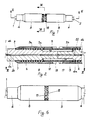
- a connecting group for two optic fibres 1,2 comprises, at the end of each tape, respective connectors 3a, 3b, formed by a pair of ferrules or elements 4a, 4b for housing the fibres, the optic fibres are tightened in position between said ferrules; a sleeve 5 is arranged around each pair of ferrules 4 said sleeve keeps the ferrules tightened together in their respective frontal zone.
- a resilient element rests against a rear end 5a of the sleeve 5, said resilient element have the shape of an helical spring, that acts at the opposite end against the annular bottom 7 of a ring nut 8, that surrounds the ferrules and can axially slides on them; a shoulder 9 forms means for stopping the sliding of the ring nut 8 under the action of the spring 7.
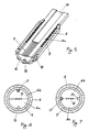
- Each ferrule 4, as it can be better seen in fig. 5, is formed by a generally semi-cylindrical element, on the axial flat surface 10 of said element there are several grooves 11, suitable for housing, with great precision, fiber ends 12 of a tape of optic fibres, said ends 12 being partially stripped of their common outer coating 13 made of plastic material.
- a remaining part of the plastic coating 13 is housed in a recess 14 arranged in a rear zone of the ferrule. 1
- the ferrules 4a, 4b are also provided, in a plane perpendicular to the surface 10, with grooves 15 extending for a part of the length of a ferrule starting from a front surface 16; respective pins 17 are housed in the grooves 15, said pins are tightened against the bottom of the respective grooves of the sleeve 5.
- each pair of ferrules, forming a connector has a pin housed in the bottom of the groove, while the second groove is without a pin, in order to allow the insertion in said groove of the corresponding pin housed in the second connector.
- the ring nut 8 has one end facing the front face 16 of the corresponding connector, shaped with a profile provided of restraining teeth 18, said teeth are suited for engaging with corresponding restraining teeth of the ring nut of the connector arranged in front of said ring nut 8; the enlarged configuration of the teeth 18, shown in fig. 8, considers the presence of undercut 19 and said configuration allows the engagement of opposite ring nuts after an axial insertion and a rotation for coupling the teeth 19 among them, said teeth are kept in a tightened condition thanks to the action of the springs 6, insuring in this way the foreseen contact pressure between the surfaces 16 of the connectors facing each other.
- the configuration exhibited by the restraining teeth 18 is to be considered by way of example, in fact many other alternative configurations are possible, such as a joint for rotation, or a bayonet joint or by means of an elastic deformation.
- the structure according to the invention allows particularly simple assembling operation of the connector to the end of the optic cable: for this reason the end of the optic fiber tape is stripped of its corresponding coating made of plastic material for a certain segment, leaving uncovered the fibres; the same fibres are therefore housed inside the grooves 11 of a ferrule 4a, while a part of the tape is housed in a recess 14 of the same ferrule.
- the grooves 11 and the recess 14 are dimensioned in order to house the optic fibres and the tape for half of their thickness respectively; a second ferrule 4b is therefore arranged on the ferrule 4a, surrounding the fibres and the end of the tape.
- Adhesive introduced in the recess 14 before joining the two ferrules 4a, 4b or fed through a hole 20 of similar holes in the same recess allows to keep integrally locked the fiber tape in its housing without exerting unacceptable mechanical stresses to the same fibres.
- a ring nut 8 After having joined the two ferrules, which form a body that is generally cylindrical, a ring nut 8 is inserted, said ring nut 8 is able to slide until it rests against the shoulder 9; afterwards the spring 6 is arranged to rest against the annular bottom 7 of the ring nut and then the sleeve 5 is force fitted on the front part of the joined ferrules, keeping said ferrules strictly locked together.
- the front surface 16 of the ferrules and the surface of the collar that surrounds the ferrules is therefore lapped, to insure the perfect flatness and smoothness for the optic coupling.
- the sleeve 5 can be suitable inserted on the same ferrules with an end that is a little backward with respect to the surface 16, so that the sleeve is not subjected to the lapping operations.
- a pin 17 is then force fitted in a corresponding groove 15 between the same groove and the sleeve 5.
- the pin 17 is suitable inserted in the groove 15 for more than a half of its length, while its projecting portion is inserted, when the two connectors are coupled, in the empty groove of the other connector: in this way it is obtained a friction constraint which is considerably stronger where the inserted segment of the pin is longer, therefore when the two connectors are separated, each pin stays integral with the connector in which the pin is more inserted, leaving the same connectors with an alignment pin and an empty groove, ready without further operations for a new connection with other similar connectors.
- Two connectors carried out and assembled in the above mentioned way, can be coupled together by introducing the corresponding pins in the corresponding grooves of the faced connector, keeping in contact the lapped coupling faces 15 and keeping tightened together the connectors after having carried out the mutual engagement of the ring nuts 8 axially pushed one against the other: in this conditions the springs 6 insure a constant pressure between the faces 16, suitable to guarantee the correct optical coupling.
- the ferrules 4 are preferably made by moulding mith dimensionally stable plastic material, such as mineral powders filled resins, insuring the requested precision and the likeness among the pieces; the configuration of the ferrules is particularly suited to carry out a mould for this object, because said ferrules are formed by elements devoid of through holes for housing the fibres, on the opposite the fibres have their housing in outwardly opened grooves, whose impression, for the manufacture by mould, can be obtained with the requested precision.
- mith dimensionally stable plastic material such as mineral powders filled resins
- the sleeve 5 is preferably carried out in metallic material, for example steel, brass or similar material, in this way it can exert a tightening action on the ferrules and on the pin 17, avoiding that the force fitting on the pins could stress the adhesive that block the tape 1 or 2 in the housing, causing the detachment of the ferrules, after repeated connections and separations of the connectors.
- metallic material for example steel, brass or similar material
- the configuration of the ferrules 4, where the grooves for the pins are arranged in a plane perpendicular to the separation plane between the same ferrules, where the housings for the fibres are carried out, allows to place a large number of fibres with a particularly reduced outer encumbrance, fitting for example in the same connector a tape with 10 fibres; when it is not necessary to house a large number of fibres, it is also possible to carry out the ferrules, according to an alternative embodiment shown in fig.
- this configuration limits, under the same outer encumbrance, the width of the fiber tape that can be housed, that is the fiber number arranged on a single connector but it compels to maintain the requested coupling precision of about 1 ⁇ m, only for the surface having the grooves for the fibres and the pins, meanwhile the precision requested for the remaining outer surface is inferior, because it has just the function to support the sleeve 5 which tightens the ferrules, therefore this surface is easier to carry out.
- the connector structure according to the invention is therefore particularly convenient, both for its compact size, that allows to house a high number of connectors in a reduced volume, and for the simple assembly that it shows, requesting the assembling, in a sequence, of a reduced number of pieces for the application of a connector to the end of an optic fiber tape; moreover the described structure allows to avoid, during the connection of the two connectors, to arrange outer resilient elements to lock the connectors together because it is sufficient to engage the nut rings.
Landscapes
- Physics & Mathematics (AREA)
- General Physics & Mathematics (AREA)
- Optics & Photonics (AREA)
- Mechanical Coupling Of Light Guides (AREA)
- Light Guides In General And Applications Therefor (AREA)
Applications Claiming Priority (2)
| Application Number | Priority Date | Filing Date | Title |
|---|---|---|---|
| IT02204089A IT1237091B (it) | 1989-10-17 | 1989-10-17 | Gruppo compatto di connessione separabile per fibre ottiche riunite a nastro. |
| IT2204089 | 1989-10-17 |
Publications (2)
| Publication Number | Publication Date |
|---|---|
| EP0423581A2 true EP0423581A2 (de) | 1991-04-24 |
| EP0423581A3 EP0423581A3 (en) | 1991-07-17 |
Family
ID=11190586
Family Applications (1)
| Application Number | Title | Priority Date | Filing Date |
|---|---|---|---|
| EP19900119272 Withdrawn EP0423581A3 (en) | 1989-10-17 | 1990-10-08 | Separable compact connecting group for optic fibres forming a tape |
Country Status (11)
| Country | Link |
|---|---|
| US (1) | US5093881A (de) |
| EP (1) | EP0423581A3 (de) |
| JP (1) | JPH03171018A (de) |
| AR (1) | AR245298A1 (de) |
| AU (1) | AU632623B2 (de) |
| BR (1) | BR9005338A (de) |
| CA (1) | CA2027732C (de) |
| IT (1) | IT1237091B (de) |
| MX (1) | MX172160B (de) |
| NZ (1) | NZ235543A (de) |
| PE (1) | PE4691A1 (de) |
Cited By (6)
| Publication number | Priority date | Publication date | Assignee | Title |
|---|---|---|---|---|
| WO2000005610A1 (en) * | 1997-07-25 | 2000-02-03 | Raytheon Company | Fiber optic connector |
| EP1020745A3 (de) * | 1998-12-31 | 2001-08-22 | Siecor Operations, LLC | Faseroptischer Stecker kompatibel mit einem MTRJ-Stecker und mit einem im wesentlichen zylindrischen Steckerstift |
| EP0843834B1 (de) * | 1995-08-10 | 2002-07-03 | BICC Public Limited Company | Installationsverfahren für ein optisches faserelement und optisches faserelement für ein derartiges verfahren |
| EP1092994A3 (de) * | 1999-10-11 | 2004-01-02 | Lucent Technologies Inc. | Optische Stecker mit Hochdensität |
| WO2004017117A3 (en) * | 2002-08-16 | 2004-07-08 | Optocon Inc | High precision optical fiber alignment components |
| US7311449B2 (en) | 2002-08-16 | 2007-12-25 | Nanoprecision Products, Inc. | High precision optoelectronic components |
Families Citing this family (27)
| Publication number | Priority date | Publication date | Assignee | Title |
|---|---|---|---|---|
| US5210810A (en) * | 1991-12-19 | 1993-05-11 | At&T Bell Laboratories | Hermaphroditic connector for single fiber optical cable |
| TW213987B (de) * | 1991-12-19 | 1993-10-01 | American Telephone & Telegraph | |
| US5189721A (en) * | 1992-02-14 | 1993-02-23 | W. L. Gore & Associates, Inc. | Optical fiber ribbon cable |
| US5727101A (en) * | 1995-10-06 | 1998-03-10 | Siecor Corporation | Monolithic ferrule for receiving and positioning multiple optical fibers and an optical fiber connector incorporating same |
| KR0171384B1 (ko) * | 1995-11-09 | 1999-05-01 | 양승택 | 리본형 광케이블용 다심 광커넥터 |
| US6045270A (en) | 1995-12-22 | 2000-04-04 | Methode Electronics, Inc. | Massive parallel optical interconnect system |
| US6095695A (en) * | 1996-10-28 | 2000-08-01 | Sumitomo Electric Industries, Ltd. | Optical connector, and using method and tool thereof |
| DE19802190C1 (de) | 1998-01-16 | 1999-09-02 | Siemens Ag | Mehrkanaliges optisches Modul |
| US6371658B2 (en) * | 1998-02-24 | 2002-04-16 | Jds Fitel Inc. | Tuned multiple fiber optic connector |
| US6173097B1 (en) | 1998-07-01 | 2001-01-09 | Siecor Operations, Llc | Field installable multifiber connector |
| DE19834986A1 (de) * | 1998-08-03 | 2000-02-10 | W W Fischer Sa Apples | Steckeranordnung für Lichtwellenleiter |
| US6149313A (en) * | 1998-12-31 | 2000-11-21 | Siecor Operations, Llc | Gender selectable fiber optic connector and associated fabrication method |
| US6442318B1 (en) | 1999-11-23 | 2002-08-27 | Schott Fiber Optics, Inc. | Prefabricated optical fiber ribbon cable for connectorizing with a terminal connector and methods of connectorizing and fabricating the same |
| US6439780B1 (en) * | 2000-08-31 | 2002-08-27 | Corning Cable Systems Llc | Field-installable fiber optic ribbon connector and installation tool |
| JP3652621B2 (ja) * | 2001-05-08 | 2005-05-25 | 株式会社オートネットワーク技術研究所 | 光中継コネクタ装置及び光中継コネクタ |
| RU2389049C2 (ru) * | 2002-08-16 | 2010-05-10 | Нанопресизион Продактс, Инк. | Высокоточные оптоэлектронные компоненты |
| AU2006236409B2 (en) * | 2005-04-19 | 2011-05-19 | Adc Telecommunications, Inc. | Loop back plug and method |
| KR100773175B1 (ko) * | 2006-06-21 | 2007-11-02 | 부산대학교 산학협력단 | 광 접속기 |
| TWI398684B (zh) * | 2008-07-25 | 2013-06-11 | 瑞軒科技股份有限公司 | 光纖連接器與光纖連接器組 |
| US7841778B2 (en) * | 2008-12-19 | 2010-11-30 | The Furukawa Electric Co., Ltd. | Optical connector |
| CN107561650B (zh) * | 2011-12-22 | 2021-07-23 | 艾瑞得光导纤维公司 | 非接触多纤光纤连接器 |
| US10545294B1 (en) | 2019-07-08 | 2020-01-28 | Arrayed Fiberoptics Corporation | Microfabrication method for optical components |
| EP2939056A1 (de) * | 2012-12-26 | 2015-11-04 | Commscope Inc. of North Carolina | Nuten zur bindung von hülsen an fasern |
| WO2016069789A1 (en) * | 2014-10-28 | 2016-05-06 | Finisar Corporation | Multi-channel optoelectronic subassemblies |
| US9851509B2 (en) * | 2016-03-31 | 2017-12-26 | Cisco Technology, Inc. | Passive alignment with optical fibers using ferrule member |
| US11333835B2 (en) | 2019-07-08 | 2022-05-17 | Arrayed Fiberoptics Corporation | Microfabrication method for optical components |
| US20240061188A1 (en) * | 2021-01-20 | 2024-02-22 | Nippon Telegraph And Telephone Corporation | Cylindrical multi-core ferrule and optical connector |
Family Cites Families (8)
| Publication number | Priority date | Publication date | Assignee | Title |
|---|---|---|---|---|
| US4009931A (en) * | 1974-03-20 | 1977-03-01 | The Deutsch Company Electronic Components Division | Optical waveguide connector |
| US4279469A (en) * | 1975-05-27 | 1981-07-21 | The United States Of America As Represented By The Secretary Of The Navy | Separable fiber optic cable connector |
| US4140366A (en) * | 1977-04-19 | 1979-02-20 | Bunker Ramo Corporation | Fiber optic connector assembly |
| NL7808742A (nl) * | 1977-11-04 | 1979-05-08 | Thomas & Betts Corp | Dubbele koppeling voor optische vezels. |
| US4320938A (en) * | 1979-12-26 | 1982-03-23 | Bell Telephone Laboratories, Incorporated | Resilient optical fiber connector |
| AU572342B2 (en) * | 1984-09-04 | 1988-05-05 | Nippon Telegraph & Telephone Corporation | Optical connector |
| NL8601855A (nl) * | 1986-07-16 | 1988-02-16 | Philips Nv | Connector voor het losneembaar verbinden van lichtgeleidende vezels. |
| US4921325A (en) * | 1987-12-25 | 1990-05-01 | Mitsubishi Cable Industries, Ltd. | Connector for optical fiber ribbon and a method of attaching the same |
-
1989
- 1989-10-17 IT IT02204089A patent/IT1237091B/it active IP Right Grant
-
1990
- 1990-09-26 AU AU63254/90A patent/AU632623B2/en not_active Ceased
- 1990-10-02 NZ NZ235543A patent/NZ235543A/xx unknown
- 1990-10-08 EP EP19900119272 patent/EP0423581A3/en not_active Withdrawn
- 1990-10-12 US US07/596,783 patent/US5093881A/en not_active Expired - Fee Related
- 1990-10-12 PE PE1990176068A patent/PE4691A1/es unknown
- 1990-10-16 AR AR90318091A patent/AR245298A1/es active
- 1990-10-16 CA CA002027732A patent/CA2027732C/en not_active Expired - Fee Related
- 1990-10-17 JP JP2278869A patent/JPH03171018A/ja active Pending
- 1990-10-17 MX MX022895A patent/MX172160B/es unknown
- 1990-10-17 BR BR909005338A patent/BR9005338A/pt not_active IP Right Cessation
Cited By (10)
| Publication number | Priority date | Publication date | Assignee | Title |
|---|---|---|---|---|
| EP0843834B1 (de) * | 1995-08-10 | 2002-07-03 | BICC Public Limited Company | Installationsverfahren für ein optisches faserelement und optisches faserelement für ein derartiges verfahren |
| WO2000005610A1 (en) * | 1997-07-25 | 2000-02-03 | Raytheon Company | Fiber optic connector |
| US6062739A (en) * | 1997-07-25 | 2000-05-16 | Raytheon Company | Fiber optic connector |
| EP1020745A3 (de) * | 1998-12-31 | 2001-08-22 | Siecor Operations, LLC | Faseroptischer Stecker kompatibel mit einem MTRJ-Stecker und mit einem im wesentlichen zylindrischen Steckerstift |
| EP1092994A3 (de) * | 1999-10-11 | 2004-01-02 | Lucent Technologies Inc. | Optische Stecker mit Hochdensität |
| WO2004017117A3 (en) * | 2002-08-16 | 2004-07-08 | Optocon Inc | High precision optical fiber alignment components |
| US7311449B2 (en) | 2002-08-16 | 2007-12-25 | Nanoprecision Products, Inc. | High precision optoelectronic components |
| US7343770B2 (en) | 2002-08-16 | 2008-03-18 | Nanoprecision Products, Inc. | Stamping system for manufacturing high tolerance parts |
| CN100504474C (zh) * | 2002-08-16 | 2009-06-24 | 毫微精密产品股份有限公司 | 高精度光纤对准元件 |
| AU2003263930B2 (en) * | 2002-08-16 | 2009-08-27 | Nanoprecision Products, Inc | High precision optical fiber alignment components |
Also Published As
| Publication number | Publication date |
|---|---|
| US5093881A (en) | 1992-03-03 |
| PE4691A1 (es) | 1991-02-27 |
| CA2027732A1 (en) | 1991-04-18 |
| AU632623B2 (en) | 1993-01-07 |
| BR9005338A (pt) | 1991-09-17 |
| AU6325490A (en) | 1991-04-26 |
| NZ235543A (en) | 1993-03-26 |
| MX172160B (es) | 1993-12-06 |
| JPH03171018A (ja) | 1991-07-24 |
| CA2027732C (en) | 1997-01-07 |
| IT8922040A0 (it) | 1989-10-17 |
| EP0423581A3 (en) | 1991-07-17 |
| IT8922040A1 (it) | 1991-04-17 |
| AR245298A1 (es) | 1993-12-30 |
| IT1237091B (it) | 1993-05-18 |
Similar Documents
| Publication | Publication Date | Title |
|---|---|---|
| EP0423581A2 (de) | Auftrennbare, kompakte Verbindungseinheit für Glasfaserbandkabel | |
| EP0223608B1 (de) | Optischer Faserstecker | |
| US5732175A (en) | Connecting system for fiber optic termination | |
| AU683837B2 (en) | Adhesiveless connector for optical fibers | |
| US4895425A (en) | Plug-in optical fiber connector | |
| US5283848A (en) | Circular multi-fiber fiber-optic connector | |
| TW513585B (en) | Fiber optic connector | |
| US5761360A (en) | Fiber optic connector with fiber gripping means | |
| US6193421B1 (en) | Optical connector and a method of attaching the same | |
| US4652082A (en) | Angled electro optic connector | |
| US5054879A (en) | Push/pull fiber optic connector | |
| EP0418503A1 (de) | Faseroptische Spleisseinheit | |
| JPS6221108A (ja) | 光フアイバケ−ブルコネクタ | |
| BE900781A (nl) | Verbindingsinrichting voor optische vezels. | |
| US4323300A (en) | Optical fibre connectors | |
| US4296999A (en) | Optical fibre connectors | |
| US4217029A (en) | Interlocking precision optical fiber connector or support | |
| US5727102A (en) | Multifiber optical connector for optical ribbon cable | |
| EP0421305B1 (de) | Faseroptische Spleisseinheit | |
| US5005942A (en) | Fiber optic splice assembly | |
| US4818061A (en) | Ferrule for connecting optical fibers and optical connector using it | |
| US4676588A (en) | Fiber optic connector | |
| US4405201A (en) | Fiber optic connector | |
| US7641397B2 (en) | Optical connector | |
| JP5160706B2 (ja) | 光ファイバーケーブルの端末装置 |
Legal Events
| Date | Code | Title | Description |
|---|---|---|---|
| PUAI | Public reference made under article 153(3) epc to a published international application that has entered the european phase |
Free format text: ORIGINAL CODE: 0009012 |
|
| AK | Designated contracting states |
Kind code of ref document: A2 Designated state(s): DE ES FR GB |
|
| PUAL | Search report despatched |
Free format text: ORIGINAL CODE: 0009013 |
|
| AK | Designated contracting states |
Kind code of ref document: A3 Designated state(s): DE ES FR GB |
|
| RAP1 | Party data changed (applicant data changed or rights of an application transferred) |
Owner name: PIRELLI CAVI S.P.A. |
|
| 17P | Request for examination filed |
Effective date: 19920113 |
|
| 17Q | First examination report despatched |
Effective date: 19930805 |
|
| RAP1 | Party data changed (applicant data changed or rights of an application transferred) |
Owner name: PIRELLI CAVI S.P.A. |
|
| STAA | Information on the status of an ep patent application or granted ep patent |
Free format text: STATUS: THE APPLICATION HAS BEEN WITHDRAWN |
|
| 18W | Application withdrawn |
Withdrawal date: 19940918 |