EP0423891A1 - Méthode pour enregistrer et déceler un modèle de rayonnement ionisant - Google Patents
Méthode pour enregistrer et déceler un modèle de rayonnement ionisant Download PDFInfo
- Publication number
- EP0423891A1 EP0423891A1 EP90202732A EP90202732A EP0423891A1 EP 0423891 A1 EP0423891 A1 EP 0423891A1 EP 90202732 A EP90202732 A EP 90202732A EP 90202732 A EP90202732 A EP 90202732A EP 0423891 A1 EP0423891 A1 EP 0423891A1
- Authority
- EP
- European Patent Office
- Prior art keywords
- image
- radiation
- recording material
- luminescent
- group
- Prior art date
- Legal status (The legal status is an assumption and is not a legal conclusion. Google has not performed a legal analysis and makes no representation as to the accuracy of the status listed.)
- Granted
Links
Images

Classifications
-
- G—PHYSICS
- G01—MEASURING; TESTING
- G01T—MEASUREMENT OF NUCLEAR OR X-RADIATION
- G01T1/00—Measuring X-radiation, gamma radiation, corpuscular radiation, or cosmic radiation
- G01T1/16—Measuring radiation intensity
- G01T1/20—Measuring radiation intensity with scintillation detectors
- G01T1/204—Measuring radiation intensity with scintillation detectors the detector being a liquid
- G01T1/2042—Composition for liquid scintillation systems
-
- C—CHEMISTRY; METALLURGY
- C09—DYES; PAINTS; POLISHES; NATURAL RESINS; ADHESIVES; COMPOSITIONS NOT OTHERWISE PROVIDED FOR; APPLICATIONS OF MATERIALS NOT OTHERWISE PROVIDED FOR
- C09K—MATERIALS FOR MISCELLANEOUS APPLICATIONS, NOT PROVIDED FOR ELSEWHERE
- C09K11/00—Luminescent materials, e.g. electroluminescent or chemiluminescent
- C09K11/06—Luminescent materials, e.g. electroluminescent or chemiluminescent containing organic luminescent materials
-
- G—PHYSICS
- G21—NUCLEAR PHYSICS; NUCLEAR ENGINEERING
- G21K—HANDLING OF PARTICLES OR IONISING RADIATION NOT OTHERWISE PROVIDED FOR; IRRADIATION DEVICES; GAMMA RAY OR X-RAY MICROSCOPES
- G21K4/00—Conversion screens for the conversion of the spatial distribution of X-rays or particle radiation into visible images, e.g. fluoroscopic screens
Definitions
- This invention relates to a method for recording an image of ionizing radiation in the form of a pattern of (a) luminescent compound(s) the luminescence of which is stimulated to produce a pattern of fluorescent light that is detected.
- a method of producing a recorded image corresponding to a releasably stored image of a pattern of high energy radiation comprises the steps of : releasing the stored image as emitted light on a point by point basis and converting the image into electrical energy modulated in accordance with the point by point intensity of the light emitted; converting the modulated electrical energy into correspondingly modulated light, and recording an image with said modulated light that represents the high energy radiation pattern on a point by point basis.
- the medium for releasably storing an image representative of the pattern of high energy radiation is a storage phosphor transparent to its own emitted radiation. Examples of applied phosphors are SrS:Ce,Sm and La2O2S:Eu,Sm.
- the storage phosphors elected for stimulable radiography with visible light or infra-red light are europium doped alkaline earth metal fluorohalide phosphors represented by the general formula (Ba 1-x M x II )FXyA, representatives of which such as BaFBr:Eu have been described already in GB-P 1 419 169 for use in X-ray intensifying screens.
- the image resolution obtained with stimulable phosphor panels scanned with a laser beam for producing stimulated light emission that is detected and amplified by photomultiplier is approximately only 2.5 line pairs per millimeter, whereas with classical X-ray image intensifying screens more than 5 line pairs can be reproduced.
- Photostimulable phosphors do not permanently retain the stored energy, normally the storage time is not longer than 8 hours during which the stored energy image fades gradually. The stored image cannot be stimulated repeatedly which makes it impossible to produce a series of read-out patterns.
- Known stimulable phosphors such as BaFBr:Eu2+ have response times of the order of 0.5 microseconds which limits the maximum rate at which the information can be scanned with a laser beam without impairing the spatial resolution.
- a particular point to be noted when using stimulable storage phosphor screens is their property to accumulate the ionizing energy coming from the environment, which is particularly disadvantageous when radiographs have to be made in circumstances of increased radioactivity, e.g. due to a nuclear incident.
- the classical radiographic X-ray intensifying screen-silver halide emulsion film combination will also fail in such circumstances because of the fact that penetrating ionizing radiation emitted in the environment will produce accumulated fog in highly photosensitive silver halide emulsion materials used in X-ray recording with X-ray conversion screens.
- a storage medium for optical data recording which medium contains a dye-forming combination which on exposure to light within a first range of wavelengths reacts irreversibly to form a dye, but is substantially insensitive to light within a second range of wavelengths that is capable of energizing the dye to produce luminescence.
- An example of dye forming combination by means of which a latent luminescence image can be produced is on the basis of benzofuran and dibromomaleic anhydride.
- both the recording of the information as well as the reading of it can be carried out simultaneously or successiveively, depending on whether the recording layer is energized to luminescence either simultaneously over a wide area or successiveively by line-by-line scanning by means of ultra-violet light within the second range of wavelengths.
- a laser beam may be used, e.g. the emission radiation of certain nobel gas lasers such as Ar+ or Kr+ lasers.
- an electronic display device e.g. a cathode ray tube or used to modulate printing light, e.g. of a laser beam.
- a method for recording an image of ionizing radiation comprises the steps of :
- a method for recording an image of ionizing radiation comprises the steps of :
- said inorganic compounds for producing said quenching substances are non-silver halide compounds, preferably metal compounds that can split off halide photolytically and wherein the metal has an atomic number of at least 80.
- ionizing radiation in the present description is understood X-ray radiation, Gamma ray radiation, fast electron radiation, e.g. of cathode ray tube, Beta-ray radiation and neutron radiation. Said ionizing radiation is also known under the name high energy radiation.
- the ionizing radiation is photochemically active radiation that exposes the recording element without the intermediary of an element containing at least one phosphor.
- a combination suitable for radiography comprising (1) at least one fluorescent screen containing at least one phosphor layer capable of emitting photochemically active radiation when irradiated by ionizing radiation, and 2) a photosensitlve recording material containing non-differentially (a) photo-quenchable luminescent compound(s) and/or (a) luminescent compound(s) in combination with compound(s) yielding by the action of said photochemically active radiation (a) compound(s) reducing or quenching the luminescence of said luminescent compound(s), the luminescence of which can be stimulated by radiation having a wavelength or wavelength range differing from the wavelength or wavelength range of the photochemically active radiation emitted by said screen(s).
- photochemically active radiation emitted by said phospor layer is understood ultraviolet, visible and infrared radiation, in particular electromagnetic radiation in the wavelength range of 250 to 750 nm.
- phosphor screens are used that convert ionizing radiation into light situated in the 250 to 750 nm wavelength range.
- photochemical systems that are originally only sensitive to ultraviolet radiation, i.e. to 250 to 400 nm wavelength radiation, can be spectrally sensitized to become sensitive to visible light and/or infrared radiation by using appropriate spectral sensitizing agents.
- luminescent relates to “fluorescent” and “phosphorescent” as well; the phenomenon of fluorescence being restricted to fluorescent light emission that stops almost immediately (within less than 1 millisecond) after the photostimulation, whereas phosphorescence lasts much longer and may be in the order of seconds and even hours.
- tantalate phosphors can be prepared by a method described in published European Patent applications No. 0 011 909 or 0 202 875.
- Suitable short wavelength UV-emitting phosphors are lead-activated strontium haloborates described by A. Meijerink et al., in Journal of Solid State Chemistry 76 , 115-123 (1988) which phosphors have an emission situated at about 280 nm.
- Other useful short wavelength UV-emitting phosphors are lead-activated Ba,Zn silicates described in Dutch Patent 104 632. These phosphors have emission peaks at 290 and 305 nm.
- UV-emitting phosphors also called near ultraviolet region emitting phosphors
- US-P 3,702,828 relating to europium-activated barium and strontium, calcium, aluminum fluoride phosphors with sharp UV emission at 360 nm.
- the phosphors used according to the present invention are incorporated in particulate form in a binder material known for that purpose to those skilled in the art.
- the binder layer incorporating the dispersed phosphor particles is usually applied onto a sheet support, e.g. cardboard, resin base or metal support, e.g. aluminium.
- the phosphor binder layer may contain screening dyes to improve the image sharpness and the phosphor layer may be applied on a light reflecting base for improving the light output.
- a usual phosphor coverage is in the range of 100 g/m2 to 1500 g/m2.
- Suitable luminescent compounds and quenching substances that can be photochemically formed are listed in the following Table 2.
- TABLE 2 Luminescent compound Quencher Acridinium ion Br ⁇ ions, Co2+ ions eosine H+, at pH lower than 4 fluoresceine H+, at pH lower than 4 uranyl sulphate HCl resorufin (sodium salt) HBr or HI 9,10-dihydroxy-anthracene Oxidant, e.g. I2.
- Phenoxazine dyes e.g. resorufin
- the acidification proceeds image-wise e.g. by using a photo-sensitive substance, e.g. CBr4 or PbI2, yielding halogen photoradicals that react with a hydrogen donor to form a hydrogen halide acid.
- a photo-sensitive substance e.g. CBr4 or PbI2
- fluorescent compounds such as 9,10-dihydroxy-anthracene and 1,5-anthracenediol are photo-oxidized and loose their fluorescent properties by oxidation and transformation into the corresponding quinone.
- photolytically decomposing organic polyhalogen compounds e.g. carbon tetrabromide and iodoform
- photolytically decomposing inorganic metal halides such as silver chloride, bromide or iodide or lead bromide or iodide.
- the latent luminescent image is produced without wet processing step(s), so in a dry way.
- the reduction or quenching of the luminescence is speeded up by heat.
- the reduction or quenching of fluorescence based on a reaction of a luminescent compound with an acid or based on a redox-reaction may be speeded up by heat and/or the presence of minor amounts of water already applied or present in the recording material in the exposure stage.
- Other substances that may speed up in some instances the luminescence quenching are heat-sensitive base-releasing agents as described e.g. in European Patent application (EPA) 0 120 306, and thermosolvents, also called heat solvents as described e.g.
- the image-wise fluorescence quenching proceeds in a photosensitive thermally developable recording material for forming silver images, said material comprising :
- said sulfamino compounds are used as electron donor compounds capable of reducing non-diffusing reducible colour providing compounds which release a diffusible dye under photographic development conditions.
- said sulfamino compounds are combined with heat-developable photosensltive materials that contain a dye-releasing compound of reducing nature and are effective in inhibiting air oxidation thereof, reduce thereby fog or promote heat development to produce a dye image of high density.
- a recording layer provided on a support contains at least one sulfamino reducing agent according to general formula (I), preferably according to one of the general formulae (II) or (III), in operative contact with a substantially light-insensitive organic silver salt and a photosensitive silver halide which produces a catalyst upon light exposure to accelerate the reaction between the organic silver salt and the reducing agent, and a source of mercuric ions in an amount sufficient to provide a lighter image background after aging, light exposure and heating, than would be obtained in the complete absence of the mercuric ion and up to 0.07 moles of mercury per mole of silver salt.
- general formula (I) preferably according to one of the general formulae (II) or (III)
- the mercuric ion may be introduced in the photographic material in any desired manner, e.g. according to onen of the embodiments described In GB-P 1 264 532. It has been found particularly convenient to introduce the mercuric ion in the form of mercurlc halide or mercuric acetate.
- operative contact is meant here that said reducing sulfamino compound in the heating treatment of the method according to the present invention is capable of reducing the organic silver salt in the photo-exposed areas of the recording material.
- substantially light-insensitive it is not meant that the organic silver salt must be completely insensitive to light, but that it should be at least be resistant to darkening under a one day diffuse sun-light exposure to prevent destruction of photographs already obtained by the defined method.
- Preferred substantially light-insensitive silver salts are silver salts of long-chain fatty acids, e.g. silver behenate and silver stearate that are fairly stable to light light , even in the presence of moisture. These salts also called silver soaps are conventiently prepared by precipitation with silver nitrate solution from aqueous solutions of the alkali metal soaps of the corresponding fatty acids and with or without co-precipitation of the fatty acid in any desired proportion. For transparent coatings the fatty acid content is restricted or omitted.
- the silver halide can be added to the coating composition of the recording layer containing the components for the redox reaction or it can be formed in situ in the coating composition, e.g. by precipitation. In the latter case the silver ions of the silver hallde essentially originate from the substantially light-insensitive silver salt.
- the halide ion (i.e. Cl ⁇ , Br ⁇ , I ⁇ or mixture thereof) for the production of the photosensitive silver halide in situ can be supplied in different manners.
- One convenient procedure involves briefly exposing the surface of the silver salt particles or coating to the vapours of one or more halogen acids, the extent of the reaction being controlled by adjusting both the concentration of the vapour and the time of the exposure.
- the halide ion is provided from a liquid medium containing e.g. mercuric halide.
- a liquid medium containing e.g. mercuric halide.
- Other methods for forming the light-sensitive silver halide in situ are described in GB-P 1 366 298.
- the photosensitive silver halide is formed in the presence of an amphiphilic copolymer serving as silver halide peptizer as described in US-P 3,706,565, and redispersed in a non-aqueous medium comprising the organic substantially light-insensitive silver salt.
- ingredients useful in the manufacture of a recording material for producing a retained latent fluorescent image according to the present invention are ingredients commonly applied in photothermographic silver halide recording materials.
- heat-sensitive alkali precursors include heat-sensitive alkali precursors, antifoggants, reducing agents other than the presently used fluorescent sulfamino compounds, silver toning agents, chemical sensitizing agents, spectral sensitizing agents, coating aids, filter dyes and anti-halation dyes, the latter dyes being applied underneath the recording layer or at the side of the support opposite the recording layer.
- heat-sensitive alkali precursors include antifoggants, reducing agents other than the presently used fluorescent sulfamino compounds, silver toning agents, chemical sensitizing agents, spectral sensitizing agents, coating aids, filter dyes and anti-halation dyes, the latter dyes being applied underneath the recording layer or at the side of the support opposite the recording layer.
- heat-sensitive alkali-precursors are described in published EP-A
- the sulfamino reducing agent, the substantially light-insensitive organic silver salt, the photosensitive silver halide, either or not formed in situ, and optionally other ingredients of the type defined above are applied together with an appropriate binding agent being an organic polymer.
- binding agents are copolymers of vinyl chloride and vinyl acetate or of butadiene and styrene, polyethylene, polyamide, polyisobuthylene, polyvinyl chloride, polyvinylidene chloride, poly(N-vinyl pyrrolidinone), chlorinated rubber, polyvinyl butyral, polymers of acrylic or methacrylic esters or copolymers of derivatives of acrylic acid and methacrylic acid, derivatives of cellulose such as cellulose nitrate, cellulose acetate, cellulose propionate or mixtures thereof, celluloseacetobutyrate.
- the concentration of the sulfamino reducing agent with respect to the substantially light-insensitive organic silver salt may vary within wide limits.
- a recording material suitable for use according to the method of the present invention preferably comprises said substantially light-insensitive organic silver salt and sulfamino reducing agent in a molar ratio of 1:1 to 1:10.
- the weight proportions of the components of the redox reaction and the binding agent vary between 4:1 and 1:1.
- the recording material may be in the form of a self-sustaining layer, but is preferably applied to an appropriate support.
- the support should be stable at the heat treatment (processing) temperature, which is preferably between 60 and 160 °C.
- Suitable supports are e.g. sheets or webs of paper, cellulose acetate and synthetic organic resins such as polyethylene terephthalate.
- the thickness of the photo-sensitive recording layer may be adapted to the requirements of the specific recording process operating with phosphor screens.
- a suitable layer thickness is between 5 and 100 ⁇ m.
- the support is double-side coated with a recording layer.
- the support is preferably transparent for the light used in the photostimulation of the retained fluorescent image.
- the recording layer is covered with an overcoat layer.
- the overcoat layer provides abrasion protection, resistance to deformation of the recording layer in the heat treatment processing and prevents or reduces the transfer of compounds to the contacting phosphor screens in the image-wise exposure.
- Useful overcoat materials are described in the already mentioned Research Disclosure March 1989 item 29963.
- the reducing sulfamino compounds used according to the present invention are fluorescent under the influence of ultra-violet radiation in the wavelength range of 250 to 400 nm.
- Preferred reducing sulfamino compounds have an absorption maximum in the spectral region of 300 to 400 nm, i.e. in the region of longwave ultraviolet radiation.
- stimulating light in the range of 300 to 400 nm the luminescence is activated and fluorescent light with a wavelength maximum between e.g. 440 and 550 nm is emitted.
- the heat treatment processing of the image-wise exposed recording material is simple in concept.
- the heating means may be, for example, a simple hot plate, a single or a pair of hot rollers, a heated drum, microwave heating and the like. Suitable apparatus are described e.g. in US-P 4,120,722, 4,112,280 and 4,148,575.
- the processing temperature is preferably in the range of 60 to 160 °C.
- the image-wise fluorescence quenching proceeds in a photosensitive thermally developable recording material for forming colour images, said material comprising :
- Such colour developable recording material is derived from photographic thermally developable silver salt recording materials including a p-phenylenediamine type developer and colour coupler as described e.g. in US-P 3,531,286, 3,764,328 and 4,535,056.
- the fluorescent colour coupler is e.g. the yellow biphenol colour-forming reducing agent described in US-P 4,535,056 or a fluorescent Alpha-naphthol type colour coupler capable of forming a quinonimine dye having an absorption spectrum different from its fluorescent light emission spectrum.
- 1-hydroxy-2-(N-arylcarbamoyl)-naphthalenes and especially 1-hydroxy-naphthoic acid anilide colour couplers have fluorescent properties, i.e. emit visible light when irradiated with ultra-violet light, and loose their fluorescent character when transformed by dye development of exposed silver halide into an indaniline dye, also called quinonimine dye.
- R represents an aliphatic or aromatic substituent that may be further substituted, e.g. a C12-C16 alkyl group, phenyl or substituted phenyl group
- R1 represents hydrogen or a substituent that is releasable in a coupling reaction with oxidized p-phenylenediamine, e.g. a chlorine atom.
- the dye development proceeds with a p-phenylenediamine type developing agent, e.g. a reducing agent (I) wherein R is ethyl, according to the following reaction scheme :
- Colour couplers of the 1-hydroxy-naphthoic acid anilide type that are particularly suited for use in the present method are listed with their structural formula in the following Table 3, wherein also the wavelength of the ultra-violet radiation used in the excitation and the emission-maximum of the fluorescent light of said couplers is given.
- the fluorescent light emission measurement was carried out having the couplers 1-4 dissolved in water and coupler 5 dissolved in dichloromethane.
- a halide ion such as Br ⁇ acting as quencher for fluorescent acridinium compound can be formed by UV-exposure of CBr4 or silver bromide in the presence of a hydrogen donor as described e.g. in GB-P GB-P 1 140 524 and 1 573 909.
- Fluorescence quenching Co2+ ions can be formed in a radiation-sensitive composition containing a a photoreductant and a cobalt(III)complex by means of which on UV-exposure, and optionally accelerated by heat, Co2+ ions are produced as described e.g. in Research Disclosure October 1974, Item 12617.
- Iodine acting as oxidative quencher can be formed by X-ray exposure of PbI2 or iodoform [ref. J. Chem. Ed., Vol. 50, Number 2, Feb. 1973, p. 93 and the book “Imaging Systems” by Kurt I. Jacobson and Ralph E. Jacobson - The Focal Press London and New York (1976), p. 239].
- Hydrogen iodide acting as an acid can be formed by photo-exposure of iodoform, or lead iodide in the presence of a hydrogen donor, e.g. polyvinyl alcohol, (see the above mentioned book "Imaging Systems", p. 130-131 and 239-240).
- High atomic number elements iodine and lead have high X-ray stopping power, i.e. provide a high X-ray absorption so that no transformation of X-rays into UV-radiation is necessary and the recording can proceed without X-ray conversion phosphor screen(s), i.e. screenless. Such is particularly interesting for obtaining high resolution images as are desired in non-destructive testing (NDT).
- NDT non-destructive testing
- HCl proceeds very well e.g. by reduction of (C6H5COCH2)2TeCl2 with photochemically formed dihydrophenanthrenequinone as described in GB-P 1 573 909.
- the recording material contains the luminescent substance(s) the fluorescence of which can be reduced or quenched in lightsensitive microcapsules.
- the fluorescence reducing or quenching substance(s) are contained in a permeable binder matrix in which the microcapsules are dispersed. By a photochemical reaction the content of the microcapsules becomes hardened, e.g.
- microcapsules contained in a heat-developable photographic material are given in EP 0,310,139 and JP N63/53,542 (see Chem. Abstr. 109 (1988), Ref. : 119746).
- the substance(s) responsible for the quenching of the fluorescence are contained in the microcapsules and the luminescent compound(s) are contained in the binder matrix wherein the microcapsules are dispersed.
- the light-sensitive microcapsules comprise a core material containing eosine or fluoresceine, a photosensitive silver halide and an ethylenically unsaturated polymerizable compound and a shell containing a melamine derivative-aldhyde resin dispersed in a binder-matrix containing a diffusion resistant strong acid, e.g. polymeric sulphonic acid as derived e.g. from a polyester described in EP 0 078 559.
- a diffusion resistant strong acid e.g. polymeric sulphonic acid as derived e.g. from a polyester described in EP 0 078 559.
- the recording material for use according to the present invention comprises preferably the luminescent compounds and substance(s) wherefrom photochemically a fluorescence quencher(s) can be formed in a binder.
- the recording material represents a self-supporting web or sheet.
- the self-supporting web or sheet contains a single recording element or a combination of recording elements (multi-layer system).
- the multi-layer system can be produced by a multiple layer coating system, e.g. slide hopper coating, co-extrusion, or lamination using e.g. heat, pressure and/or an adhesive.
- said luminescent compounds and substance(s) for forming (a) fluorescence quencher(s) is (are) applied as (a) supported layer(s) on a sheet or web support.
- the support is single or double-side coated, including the possibility of a combination of a plurality of recording layers of different composition.
- the support may be opaque or transparent to ultraviolet radiation and/or transparent or opaque to the emitted fluorescent light.
- Suitable supports include paper supports and film supports known from silver halide photography, e.g. cellulosetriacetate or polyethylene terephthalate supports. Other possible supports are aluminium supports and glass supports.
- the binder may be hydrophilic or hydrophobic and is preferably itself poorly absorbing in the wavelength region of the photochemically active radiation emitted by the applied phosphor screen(s) and is not fluorescent upon irradiation with the excitation light used in the fluorescent image detection and read-out stage.
- binder compounds are used having an intrinsic UV absorption below 250 nm.
- Preferred polymeric hydrophobic binders are selected from the group consisting of homopolymers and copolymers of monomers which have copolymerizable olefinic double bonds, polyvinyl acetals and cellulose esters.
- Suitable poorly UV absorbing binder materials are waterinsoluble homo- and copolymers of vinyl esters such as vinyl acetate, vinyl chloride, styrene, (meth)acrylic esters, preferably polymethylmethacrylate, acrylonitrile, vinylacetals, e.g. butyral and formal, polycarbonates, polyesters, mixed polyester-carbonates, cellulose esters, e.g. cellulose acetate butyral and cellulose alkylsuccinate.
- vinyl esters such as vinyl acetate, vinyl chloride, styrene, (meth)acrylic esters, preferably polymethylmethacrylate, acrylonitrile, vinylacetals, e.g. butyral and formal, polycarbonates, polyesters, mixed polyester-carbonates, cellulose esters, e.g. cellulose acetate butyral and cellulose alkylsuccinate.
- watersoluble polymers are poly(meth)acrylamide and N-substituted, e.g. with HOCH2- substituent, poly(meth)acrylamides.
- the total quantity of the combination of luminescent compounds and reactants forming a quencher may be 3 to 50 % by weight based on the binder and the coverage is e.g. in the range of 1 to 20 g per m2.
- the lower limit is determined actually by the detection sensitivity of the electronic detection device, e.g. phototube or photomultiplier, by means of which signal amplifications coresponding with an amplification factor 107 [ref. "Principles and Applications of Photochemistry" by Richard P. Wayne - Oxford University Press (1988), p. 165] can be obtained.
- the reactant(s) for producing the quencher are preferably used in at least a double molar quantity with respect to the lumlnescent compound(s).
- a fluorescent screen containing a phosphor emitting ultraviolet radiation when struck by said ionizing radiation is selected, said phosphor emitting ultraviolet radiation in the wavelength range wherein the conversion of luminescent compounds in the recording material into quenched luminescent compounds takes place rapidly and the photostimulation of the residual luminescent compounds proceeds with ultraviolet radiation of longer wavelength by means of which the quenching reaction proceeds substantially slower or does not proceed at all.
- the light emitted by the residual luminescent compound(s) is light of the visible light or infra-red light range that can be selectively detected with respect to the applied ultra-violet stimulating radiation by using e.g. an appropriate optical cut-off filter blocking the luminescence stimulating ultra-violet radiation.
- the photosensitive compound(s) being directly or indirectly responsible for fluorescence reduction or quenching have preferably a sensitivity to ultraviolet light within a range of very short wavelengths with a maximum between about 200 and 310 nm and a neglegible sensitivity above 350 nm.
- the luminescent compounds left after image-wise quenching have preferably an absorption maximum above 350 nm, i.e. in the region of longwave ultraviolet radiation. For example, by exposure to stimulating light in the range of 350 to 440 nm the luminescence is activated and fluorescent light with a wavelength maximum between e.g. 440 and 660 nm is emitted.
- the fluorescence stimulating exposure of the above mentioned step (3) proceeds by a simultaneous overall exposure, i.e. an exposure by flooding the recording material containing said latent image with the fluorescence stimulating radiation.
- the fluorescence stimulating exposure of the above mentioned step (3) proceeds successively, e.g. proceeds scanningwise by a successive point by point exposure of said latent image. That successive exposure proceeds preferably with a linewise scanning laser beam.
- Photostimulation of fluorescence may proceed with commonly known lamps (e.g. with high and low pressure mercury vapour lamps) or with a laser, e.g. a He-Cd laser, argon ion laser or tunable organic dye laser.
- lamps e.g. with high and low pressure mercury vapour lamps
- a laser e.g. a He-Cd laser, argon ion laser or tunable organic dye laser.
- the detection of the emitted fluorescent light proceeds photographically on a photochemical recording material, e.g. a photosensitive silver halide emulsion recording material.
- the detection of the emitted fluorescent light proceeds photoelectrically, e.g. by means of photoelectron emission in a phototube or photomultiplier providing electrical signals that may undergo an analog-digital conversion.
- the electrical signals may be stored and subjected to digital processing for improving image quality or varying image contrast (ref. Research Disclosure, April 1985, item 25235).
- the electrical analog or digital signals may be used for display on a cathode-ray tube.
- a hard copy of the recorded information may be obtained by using the electrical signals stemming from the photoelectronic detection of the fluorescent light pattern to modulate a writing laser beam associated with a photosensitive recording material, e.g. electrophotographic recording material, thermographic recording material, e.g. for thermal transfer of dyes, or photosensitive silver salt recording material.
- a photosensitive recording material e.g. electrophotographic recording material, thermographic recording material, e.g. for thermal transfer of dyes, or photosensitive silver salt recording material.
- the stimulation of the latent luminescence image proceeds preferably in a linewise fashion which may be orthogonally or spirally.
- Organic fluorescent compounds have normally photostimulation response times of the order of 10-20 nanoseconds so that, if sufficient laser beam power is used, they can be read-out substantially more rapidly than the comparatively slow stimulable phosphors.
- a photochemically produced latent luminescence image need not be erased as is the case with the reusable stimulable storage phosphor screens so that the whole recording and reading system can be simplified and the operating time shortened by the omission of a time consuming erasure step.
- the recording of the scanningwise emitted fluorescent light proceeds e.g. with a light-collector connected to a photomexcellenttiplier tube as illustrated e.g. in US-P 4 258 264, 4 748 326, 4 829 180 or 4 778 995.
- the photochemical production of a latent luminescent image in a dry way offers the benefit of direct digitization of the photostimulated luminescent image and the possibility of image processing. Digitization of the electronic output signals produces quantized gray-scale values. If an 8-bit analog-digital convertor (ADC) is employed, the resultant image will contain as many as 256 quantization steps or shades of gray. When a 12-bit ADC is employed as for chest radiography, the resultant image can have up to 4,096 quantization levels.
- ADC analog-digital convertor
- the record containing the photochemically produced luminescent image can be read at a later time since there is no substantial dark-decay of the latent luminescent image and it can be read several times without decay in fluorescence level.
- the fluorescence of the latent luminescent image obtained in the recording method according to the present invention is maintained as long as there is an input of stimulating light such being in contrast with the use of a stimulable storage phosphor screen of which the stored information is destroyed during the exposure with fluorescence stimulating radiation.
- fluorescent light emission in the method according to the present invention can be maintained as long as desired the recording of fluorescent light can occur with photographic materials having a relatively poor photosensitivity, e.g. DRY SILVER (trade name) recording materials that are exposed to the fluorescent light only by using a proper cut-off filter excluding the exposure with the light used in the photostimulation of the latent luminescent image.
- a long exposure time will provide here the necessary light dose for image recording in said rather poorly photosensitive recording material.
- a flood light or simultaneous exposure is then used preferably.
- the simultaneous exposure with stimulating light makes it likewise possible to record the image of fluorescent light with a still video camera, e.g. with CCD-array camera (CCD stands for charge coupling device) known to those skilled in the art.
- CCD-array camera CCD stands for charge coupling device
- the combination of phosphor fluorescent screen(s) and (a) recording material(s) for producing therein a latent luminescent-image according to the present invention can be used in classical clinical X-ray equipment operating with a front and back screen having the recording material for producing therein a latent luminescent image inbetween and in close contact with said screens during the X-ray exposure.
- a sheet representing the recording material used according to the present invention for obtaining a latent luminescent image may be arranged in a cassette between X-ray conversion screens.
- At least one of the fluorescent phosphor screens is provided with a reflective backing layer for reflecting the photochemically active radiation so that the radiation emitted by the phosphor screen(s) can enter several times the recording material increasing thereby the probability of its absorption and photochemical action.
- the member of the recording material containing the photosensitive substance(s) used for forming (a) luminescence quenching compound(s) during the recording stands in contact with an element reflecting the photochemically active radiation or said member is present (coated) on a reflective backing, e.g. is coated on a vacuum deposited aluminium layer, that is highly reflective for UV-radiation.
- a reflective backing e.g. is coated on a vacuum deposited aluminium layer, that is highly reflective for UV-radiation.
- Such recording material is used in combination with only one phosphor screen.
- the front screen preferentially absorbing the low-energy X-ray photons, useful in the imaging of the structure of soft tissue, low atomic number phosphors are used, whereas the higher energy part of the X-ray beam giving more information on the bone structure is absorbed or stopped in a back screen containing a higher atomic number phosphor.
- the phosphor screens are separated by an X-ray hardening filter, wherein one of the screens, the screen most close to the X-ray source and called front screen, contains a photostimulable phosphor with low X-ray stopping power and the other screen contains another photostimulable phosphor having a substantially higher X-ray stopping power for higher energy X-ray photons than said phosphor of the front screen.
- the X-ray hardening of the interscreen filter material is made e.g. of copper.
- Said combination includes a plurality of non-luminescent recording materials wherein photochemically a latent luminescent image can be produced, and wherein each of said recording materials during a single shot X-ray exposure is associated with a different X-ray conversion screen having different X-ray stopping power.
- one phosphor screen being the front screen has an effective stopping power for 15 to 25 keV X-rays and the other screen being the back screen has an effective stopping power for X-rays of 30 keV and more.
- the present method of recording an image of ionizing radiation includes autoradiography.
- An autoradiograph is a photographic record of the radioactive material within an object, produced by putting the object in contact with a photographic material.
- the radioactive object is placed in contact with or in close proximity with a phosphor screen emitting photochemically active radiation under the influence of the ionizing radiation stemming from the radioactivity in said object.
- the obtained pattern of photochemically active radiation is absorbed by the recording material wherein said latent luminescent image is formed.
- autoradiography is a laboratory process applied to microtome sections of biological tissues which contain radioisotopes, metallographic samples and the like.
- phosphor screens For use in autoradiography wherein normally only small samples are non-destructively tested it may be convenient to use phosphor screens containing the phosphor particles mixed with the compounds wherefrom the luminescence quencher(s) is (are) produced.
- the re-use of said phosphor screens is not possible when a permanent latent luminescent image is formed, but such is not that expensive when only small size phosphor screens have to be used, e.g. of the size of a microscope test object.
- NDT radiographic non-destructive testing
- the recording material used according to the present invention is arranged in a cassette for photostimulable radiography as described e.g. in published European Patent application (EP-A) 0 309 874.
- the recording materials used according to the present invention can be much more flexible than is the case with phosphor screen sheets having a thick phosphor coating their transport is much easier and the transport systems in the radiographic apparatus wherein they are applied are less cumbersome.
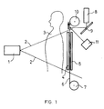
- said recording material is used in the form of a flexible web and exposed between and in contact with two prompt emitting X-ray conversion screens as illustrated in Fig. 1.
- FIG. 1 represents a schematical cross-sectional view of an apparatus suited for use in the method according to the present invention.
- Element 1 is an X-ray exposure source emitting X-rays 2 modulated by the internal structure of a person 3 to be radiographed.
- the modulated X-ray beam strikes a front X-ray conversion screen 4 and a back X-ray conversion screen 5 both said screens emitting photochemically active radiation that is absorbed by the recording material in the form of a web 6.
- the photochemically active radiation absorbed in web 6 forms therein a latent luminescent image.
- the web is supplied by an unwinding roll 7 and is during the non-exposure stage conveyed between the screens 4 and 5 which allow passage for each new image frame. In the exposure stage the screens 4 and 5 make with their phosphor layer side intimate contact with the web 6.
- the photostimulation of the photochemically obtained latent luminescent image in the web 6 proceeds with a laser beam emitted by the laser device 8, e.g. a He-Cd laser emitting continuously a 442 nm wavelength light or an argon ion laser emitting continuously ultraviolet radiation with a 351.1 or 363.8 nm wavelength or visible light with 488 nm wavelength.
- a light deflector 9 formed of a galvanometer mirror or the like deflects the laser beam so that it strikes the web 6 in linewise scanning fashion while the web 6 is wound up on the take up roll 10.
- a photoelectronic detector 11 receives the fluorescent light which is separated from the stimulating light by a cut-off filter (not shown in the drawing).
- a photomultiplier tube a photoelectric amplification channel plate may be used as the fluorescent light detecting and amplifying means. There is no need for an erasing light source.
- the read-out of the series of latent luminescent images proceeds in a later stage following the series of X-ray exposures, such being possible by the fact that the latent luminescent images obtained according to the present invention do not fade.
- the part of the web containing a series of exposed image frames is wound on an accumulator roll and cut at the required length whereupon that part is read out.
- a fine grain AgCl/gelatin-emulsion containing in finely dispersed state colour coupler No. 5 of Table 3 was coated on a subbed polyethylene terephthalate support in an amount sufficient to obtain on coating a coverage per m2 of 3.81x10 ⁇ 4 mol of said coupler, 2.86 g of gelatin and 5.88x10 ⁇ 3 mol of silver chloride.
- the single side coated recording material having at the rear side a black anti-reflection coating was arranged with its silver halide emulsion layer in contact with a phosphor screen converting X-rays in UV light corresponding with the emission spectrum given in Fig 2.
- the relative emission intensity (R.E.I.) is in the ordinate and the wavelength in nm of the emitted fluorescent light is in the abscissa.
- the phosphor screen contained undoped tantalate phosphor particles having monoclinic M structure.
- the empirical formula of said phosphor defined with atom gram coefficients is : (Y 0.998 ,Sr 0.002 ,Li 0.002 )TaO4.
- For the preparation of said phosphor reference is made to published European Patent application 0 202 875.
- the phosphor was applied at a phosphor coverage of 600 g per m2 in a polymethylmethacrylate binder on a 175 micron thick polyethylene terephthalate resin support.
- N-hydroxyethyl-N-ethyl-p-phenylene diamine 8 g hydroxylamine 1.5 g sodium sulphite (anhydrous) 4 g potassium bromide 1 g potassium carbonate (anhydrous) 65 g water up to 100 ml (pH about 10.8)
- the development was carried out at 25°C for 2 min. After development the photographic material was subjected to an acid fixing treatment, rinsed and dried.
- a positive latent luminescent image was obtained by reducing the fluorescence in the photo-exposed portions wherein by development a silver image together with a blue dye image (absorption maximum at 675 nm) was formed.
- the relative fluorescent light emission intensity (R.E.I. values) obtained by excitation at 351.1 nm were measured at a fluorescent light wavelength of 450 nm in the portions exposed to the light emitted by the phosphor screen and in the non-exposed portions. In said exposed and non-exposed portions R.E.I. values of 4.06 and 0.35 were measured respectively.
- an Argon ion laser with its 351.1 nm emission line was used.
- the emitted visible fluorescent light was detected with a photomultiplier tube through a cut-off filter having a transmission larger than 90% at wavelength (lambda) larger than 420 nm and a transmission smaller than 10 ⁇ 5 at lambda smaller than 390 nm.
- the photomultiplier was provided with a bi-alkali (Na-K) photocathode (broad absorption at 400 nm).
- the obtained electrical signals were digitized and used to modulate a writing laser beam of He-Ne laser for exposure of a red-sensitized silver halide emulsion recording material which on development yielded a high quality copy of the original aluminium step wedge.
- a homogeneous dispersion was made of 0.19 g of silver bromide grains, 1.79 g of silver behenate, 0.11 g of behenic acid in 34.5 g of a solvent mixture consisting of 5 parts of methyl ethyl ketone, 3 parts of ethanol and 2 parts of n-butanol whereto 3.36 g of polyvinyl butyral (BUTVAR B 79 - registered trade name of Monsanto) were added.
- BUTVAR B 79 - registered trade name of Monsanto polyvinyl butyral
- the single side coated photosensitive thermally developable recording material was arranged with its protective layer into contact with a phosphor screen as defined in Example 1.
- the exposed recording material was kept with its uncoated support side in contact with a hollow aluminium roller that was internally electrically heated to 118 °C.
- the recording material is suited for non-destructive testing in industrial radiography.
- a homogeneous dispersion was made of 0.32 g of silver bromide grains, 2.74 g of silver behenate, 0.15 g of palmitic acid in 34.5 g of a solvent mixture of 29 g of methyl ethyl ketone, 17.4 g of ethanol and 11.6 g of n-butanol whereto 5.65 g of polyvinyl butyral (BUTVAR B 79 - registered trade name of Monsanto) were added.
- BUTVAR B 79 polyvinyl butyral
- the single side coated photosensitive thermally developable recording material was arranged with its protective layer into contact with a phosphor screen as defined in Example 1.
- the exposed recording material was kept with its uncoated support side in contact with a hollow aluminium roller that was internally electrically heated to 118 °C.
- the recording material is suited for non-destructive testing in industrial radiography.
- a solution was made of 10 g of co(vinyl butyral/vinyl alcohol) (molar ratio 90/10) in 100 ml of a solvent mixture of 50 % of methyl ethyl ketone, 30 % of ethanol and 20 % of n-butanol.
- the sodium salt of resorufin (7-hydroxy-3H-phenoxazin-3-one sodium salt) was added in such an excess that after stirring for 1 h a not dissolved residue was left which was removed by filtering.
- To the filtered solution 1.5 g of carbon tetrabromide were added.
- the thus obtained coating composition was doctor blade coated at a wet thickness of 200 ⁇ m onto a 100 ⁇ m thick subbed polyethylene terephthalate support.
- the single side coated photosensitive print-out developable recording material was arranged with its recording layer into contact with a phosphor screen as defined in Example 1.
- a positive latent luminescent image was obtained by the image-wise quenching of the fluorescence of the resorufin.
- the quenching of the fluorescence proceeded actually by HBr, an acid formed by reaction of bromine radicals obtained from the photo-exposed CBr4 and hydrogen atoms stemming from the vinyl alcohol groups in the binder polymer serving as hydrogen donor.
- the resorufin sodium salt has an excitation maximum at 583 nm.
- the read-out proceeded with the excitation light of the 514.5 nm line of an argon ion laser.
- the emission maximum of the fluorescent light is at 609 nm, which wavelength is separated from the excitation wavelength by a proper cut-off filter followed by a photodiode detector or photomultiplier yielding sequential electrical signals by scanning the image-wise recording material with the 514.5 nm line argon ion laser beam.
- the above recording material is suited for use in industrial radiography operating with X-ray conversion screens that are emitting ultra-violet radiation.
Landscapes
- Engineering & Computer Science (AREA)
- High Energy & Nuclear Physics (AREA)
- Physics & Mathematics (AREA)
- Chemical & Material Sciences (AREA)
- Materials Engineering (AREA)
- Molecular Biology (AREA)
- Spectroscopy & Molecular Physics (AREA)
- General Physics & Mathematics (AREA)
- Health & Medical Sciences (AREA)
- Organic Chemistry (AREA)
- Life Sciences & Earth Sciences (AREA)
- General Engineering & Computer Science (AREA)
- Non-Silver Salt Photosensitive Materials And Non-Silver Salt Photography (AREA)
- Silver Salt Photography Or Processing Solution Therefor (AREA)
- Luminescent Compositions (AREA)
- Conversion Of X-Rays Into Visible Images (AREA)
- Radiography Using Non-Light Waves (AREA)
Applications Claiming Priority (2)
| Application Number | Priority Date | Filing Date | Title |
|---|---|---|---|
| EP89202676 | 1989-10-20 | ||
| EP89202676 | 1989-10-20 |
Publications (2)
| Publication Number | Publication Date |
|---|---|
| EP0423891A1 true EP0423891A1 (fr) | 1991-04-24 |
| EP0423891B1 EP0423891B1 (fr) | 1995-09-13 |
Family
ID=8202490
Family Applications (1)
| Application Number | Title | Priority Date | Filing Date |
|---|---|---|---|
| EP19900202732 Expired - Lifetime EP0423891B1 (fr) | 1989-10-20 | 1990-10-15 | Méthode pour enregistrer et déceler un modèle de rayonnement ionisant |
Country Status (3)
| Country | Link |
|---|---|
| EP (1) | EP0423891B1 (fr) |
| JP (1) | JPH03264900A (fr) |
| DE (1) | DE69022352T2 (fr) |
Cited By (8)
| Publication number | Priority date | Publication date | Assignee | Title |
|---|---|---|---|---|
| EP0775592A1 (fr) | 1995-11-27 | 1997-05-28 | Agfa-Gevaert N.V. | Procédé thermique pour former des images |
| EP0775595A1 (fr) | 1995-11-27 | 1997-05-28 | Agfa-Gevaert N.V. | Matériaux pour l'enregistrement par la chaleur avec un dérivé de l'acide phosphorique comme lubrifiant |
| EP0782043A1 (fr) | 1995-12-27 | 1997-07-02 | Agfa-Gevaert N.V. | Matériel thermographique pour l'enregistrement avec reproduction améliorée du ton |
| US6207968B1 (en) | 1997-06-30 | 2001-03-27 | Orex Computed Radiography Ltd. | Reading head for an optical scanning device |
| EP1113292A3 (fr) * | 1999-12-28 | 2003-03-12 | Fuji Photo Film Co., Ltd. | Méthode et dispositif d'emmagasinage et de reproduction d'une image obtenue par rayonnement |
| EP1074856A3 (fr) * | 1999-07-30 | 2005-12-07 | Kabushiki Kaisha Toshiba | Détecteur de radiation |
| EP1519224A3 (fr) * | 2003-09-29 | 2006-07-05 | Fuji Photo Film Co., Ltd. | Méthode de formation d'images utilisant un matériau photothermographique |
| US7264920B2 (en) | 2004-03-25 | 2007-09-04 | Fujifilm Corporation | Photothermographic material and image forming method |
Families Citing this family (1)
| Publication number | Priority date | Publication date | Assignee | Title |
|---|---|---|---|---|
| US6652996B2 (en) * | 2002-01-31 | 2003-11-25 | Eastman Kodak Company | Radiographic phosphor panel having improved speed and sharpness |
Citations (3)
| Publication number | Priority date | Publication date | Assignee | Title |
|---|---|---|---|---|
| DE1901259A1 (de) * | 1969-01-11 | 1970-08-06 | Basf Ag | Verfahren zur Fixierung,Wiedergabe und UEbertragung von Informationen |
| EP0101295A2 (fr) * | 1982-08-12 | 1984-02-22 | Konica Corporation | Procédé pour la réalisation d'images radiographiques |
| EP0209186A2 (fr) * | 1985-07-12 | 1987-01-21 | Koninklijke Philips Electronics N.V. | Dispositif pour enregistrer et extraire des images basé sur des luminophores excitables par la lumière |
-
1990
- 1990-10-15 EP EP19900202732 patent/EP0423891B1/fr not_active Expired - Lifetime
- 1990-10-15 DE DE1990622352 patent/DE69022352T2/de not_active Expired - Fee Related
- 1990-10-18 JP JP28171890A patent/JPH03264900A/ja active Pending
Patent Citations (3)
| Publication number | Priority date | Publication date | Assignee | Title |
|---|---|---|---|---|
| DE1901259A1 (de) * | 1969-01-11 | 1970-08-06 | Basf Ag | Verfahren zur Fixierung,Wiedergabe und UEbertragung von Informationen |
| EP0101295A2 (fr) * | 1982-08-12 | 1984-02-22 | Konica Corporation | Procédé pour la réalisation d'images radiographiques |
| EP0209186A2 (fr) * | 1985-07-12 | 1987-01-21 | Koninklijke Philips Electronics N.V. | Dispositif pour enregistrer et extraire des images basé sur des luminophores excitables par la lumière |
Non-Patent Citations (1)
| Title |
|---|
| DATABASE DERWENT WORLD PATENT INDEX, AN 78-77001A,"DYE IMAGE RECORDING PROCESS.." & JPA 53106125(FUJI PHOTO) 14-09-78 * |
Cited By (11)
| Publication number | Priority date | Publication date | Assignee | Title |
|---|---|---|---|---|
| EP0775592A1 (fr) | 1995-11-27 | 1997-05-28 | Agfa-Gevaert N.V. | Procédé thermique pour former des images |
| EP0775595A1 (fr) | 1995-11-27 | 1997-05-28 | Agfa-Gevaert N.V. | Matériaux pour l'enregistrement par la chaleur avec un dérivé de l'acide phosphorique comme lubrifiant |
| EP0782043A1 (fr) | 1995-12-27 | 1997-07-02 | Agfa-Gevaert N.V. | Matériel thermographique pour l'enregistrement avec reproduction améliorée du ton |
| US6207968B1 (en) | 1997-06-30 | 2001-03-27 | Orex Computed Radiography Ltd. | Reading head for an optical scanning device |
| EP1074856A3 (fr) * | 1999-07-30 | 2005-12-07 | Kabushiki Kaisha Toshiba | Détecteur de radiation |
| EP1113292A3 (fr) * | 1999-12-28 | 2003-03-12 | Fuji Photo Film Co., Ltd. | Méthode et dispositif d'emmagasinage et de reproduction d'une image obtenue par rayonnement |
| US6713776B2 (en) | 1999-12-28 | 2004-03-30 | Fuji Photo Film Co., Ltd. | Method for storing and reproducing radiation image and radiation image storage device |
| EP1519224A3 (fr) * | 2003-09-29 | 2006-07-05 | Fuji Photo Film Co., Ltd. | Méthode de formation d'images utilisant un matériau photothermographique |
| US7214476B2 (en) | 2003-09-29 | 2007-05-08 | Fujifilm Corporation | Image forming method using photothermographic material |
| CN100419575C (zh) * | 2003-09-29 | 2008-09-17 | 富士胶片株式会社 | 使用光热照相材料的图像形成方法 |
| US7264920B2 (en) | 2004-03-25 | 2007-09-04 | Fujifilm Corporation | Photothermographic material and image forming method |
Also Published As
| Publication number | Publication date |
|---|---|
| JPH03264900A (ja) | 1991-11-26 |
| DE69022352T2 (de) | 1996-04-04 |
| EP0423891B1 (fr) | 1995-09-13 |
| DE69022352D1 (de) | 1995-10-19 |
Similar Documents
| Publication | Publication Date | Title |
|---|---|---|
| US4394581A (en) | Radiation image storage panel | |
| EP0125691B1 (fr) | Méthode pour détecter une image par rayonnement | |
| US4350893A (en) | Radiation image storage panel | |
| US4320296A (en) | Method of and apparatus for recording image processing data in radiation image recording system | |
| US4496973A (en) | Radiation image read-out method and apparatus | |
| US3891852A (en) | Neutron detection and radiography | |
| US4584482A (en) | Noise erasing method and apparatus for stimulable phosphor sheet | |
| EP0772059A1 (fr) | Assemblage pour autoradiographic avec l'écran transparent | |
| EP0423891B1 (fr) | Méthode pour enregistrer et déceler un modèle de rayonnement ionisant | |
| EP0276497B1 (fr) | Procédé de production d'images radiographiques multiples | |
| EP0479437B1 (fr) | Pellicule d'enregistrement radiographique du type thermographique | |
| JPH09311200A (ja) | 放射線像変換パネル及び放射線像読取方法 | |
| US4734581A (en) | Autoradiographic process | |
| US5157263A (en) | Method for recording an image of ionizing radiation | |
| US4584483A (en) | Noise erasing method in radiation image recording and reproducing method | |
| US4480024A (en) | Industrial X-ray photothermographic system | |
| US4616135A (en) | Radiation image recording and reproducing method | |
| US7214464B2 (en) | High speed positive-working photothermographic radiographic film | |
| JPS60262100A (ja) | 放射線画像変換方法 | |
| JPH08313699A (ja) | 放射線増感スクリーン及び放射線画像変換パネル | |
| JPS60233582A (ja) | オ−トラジオグラフ測定法 | |
| JPH05257000A (ja) | 放射線画像変換方法 | |
| JPS6146946A (ja) | 放射線画像読取方法 | |
| JPH0625347B2 (ja) | 放射線画像変換パネル | |
| JPH11142598A (ja) | 放射線増感スクリーン |
Legal Events
| Date | Code | Title | Description |
|---|---|---|---|
| PUAI | Public reference made under article 153(3) epc to a published international application that has entered the european phase |
Free format text: ORIGINAL CODE: 0009012 |
|
| AK | Designated contracting states |
Kind code of ref document: A1 Designated state(s): BE DE FR GB |
|
| 17P | Request for examination filed |
Effective date: 19911005 |
|
| 17Q | First examination report despatched |
Effective date: 19941104 |
|
| GRAA | (expected) grant |
Free format text: ORIGINAL CODE: 0009210 |
|
| AK | Designated contracting states |
Kind code of ref document: B1 Designated state(s): BE DE FR GB |
|
| PG25 | Lapsed in a contracting state [announced via postgrant information from national office to epo] |
Ref country code: FR Effective date: 19950913 Ref country code: BE Effective date: 19950913 |
|
| REF | Corresponds to: |
Ref document number: 69022352 Country of ref document: DE Date of ref document: 19951019 |
|
| EN | Fr: translation not filed | ||
| PLBE | No opposition filed within time limit |
Free format text: ORIGINAL CODE: 0009261 |
|
| STAA | Information on the status of an ep patent application or granted ep patent |
Free format text: STATUS: NO OPPOSITION FILED WITHIN TIME LIMIT |
|
| PGFP | Annual fee paid to national office [announced via postgrant information from national office to epo] |
Ref country code: GB Payment date: 19960813 Year of fee payment: 7 |
|
| PGFP | Annual fee paid to national office [announced via postgrant information from national office to epo] |
Ref country code: DE Payment date: 19960816 Year of fee payment: 7 |
|
| 26N | No opposition filed | ||
| PG25 | Lapsed in a contracting state [announced via postgrant information from national office to epo] |
Ref country code: GB Free format text: LAPSE BECAUSE OF NON-PAYMENT OF DUE FEES Effective date: 19971015 |
|
| GBPC | Gb: european patent ceased through non-payment of renewal fee |
Effective date: 19971015 |
|
| PG25 | Lapsed in a contracting state [announced via postgrant information from national office to epo] |
Ref country code: DE Free format text: LAPSE BECAUSE OF NON-PAYMENT OF DUE FEES Effective date: 19980701 |