EP0424151A2 - Méthode et dispositif pour la production d'un câble optique multifibre - Google Patents
Méthode et dispositif pour la production d'un câble optique multifibre Download PDFInfo
- Publication number
- EP0424151A2 EP0424151A2 EP90311446A EP90311446A EP0424151A2 EP 0424151 A2 EP0424151 A2 EP 0424151A2 EP 90311446 A EP90311446 A EP 90311446A EP 90311446 A EP90311446 A EP 90311446A EP 0424151 A2 EP0424151 A2 EP 0424151A2
- Authority
- EP
- European Patent Office
- Prior art keywords
- sheathing
- fibre bundle
- fibres
- twisting
- fibre
- Prior art date
- Legal status (The legal status is an assumption and is not a legal conclusion. Google has not performed a legal analysis and makes no representation as to the accuracy of the status listed.)
- Granted
Links
- 239000000835 fiber Substances 0.000 title claims abstract description 90
- 238000000034 method Methods 0.000 title claims abstract description 18
- 230000003287 optical effect Effects 0.000 title claims abstract description 11
- 238000001125 extrusion Methods 0.000 claims abstract description 5
- 239000004519 grease Substances 0.000 claims description 12
- 238000001816 cooling Methods 0.000 claims description 3
- 230000002441 reversible effect Effects 0.000 claims description 3
- 230000002311 subsequent effect Effects 0.000 claims 2
- 238000013459 approach Methods 0.000 abstract 1
- 240000001307 Myosotis scorpioides Species 0.000 description 13
- 230000000694 effects Effects 0.000 description 4
- 238000004519 manufacturing process Methods 0.000 description 3
- 230000015572 biosynthetic process Effects 0.000 description 2
- 239000013307 optical fiber Substances 0.000 description 2
- 238000007792 addition Methods 0.000 description 1
- 229940000425 combination drug Drugs 0.000 description 1
- 230000006735 deficit Effects 0.000 description 1
- 239000000463 material Substances 0.000 description 1
- 230000002093 peripheral effect Effects 0.000 description 1
- 229920000136 polysorbate Polymers 0.000 description 1
- 238000007711 solidification Methods 0.000 description 1
- 230000008023 solidification Effects 0.000 description 1
- 230000003068 static effect Effects 0.000 description 1
- 230000001360 synchronised effect Effects 0.000 description 1
Images

Classifications
-
- D—TEXTILES; PAPER
- D07—ROPES; CABLES OTHER THAN ELECTRIC
- D07B—ROPES OR CABLES IN GENERAL
- D07B7/00—Details of, or auxiliary devices incorporated in, rope- or cable-making machines; Auxiliary apparatus associated with such machines
- D07B7/02—Machine details; Auxiliary devices
- D07B7/14—Machine details; Auxiliary devices for coating or wrapping ropes, cables, or component strands thereof
- D07B7/145—Coating or filling-up interstices
-
- B—PERFORMING OPERATIONS; TRANSPORTING
- B29—WORKING OF PLASTICS; WORKING OF SUBSTANCES IN A PLASTIC STATE IN GENERAL
- B29C—SHAPING OR JOINING OF PLASTICS; SHAPING OF MATERIAL IN A PLASTIC STATE, NOT OTHERWISE PROVIDED FOR; AFTER-TREATMENT OF THE SHAPED PRODUCTS, e.g. REPAIRING
- B29C53/00—Shaping by bending, folding, twisting, straightening or flattening; Apparatus therefor
- B29C53/14—Twisting
-
- D—TEXTILES; PAPER
- D07—ROPES; CABLES OTHER THAN ELECTRIC
- D07B—ROPES OR CABLES IN GENERAL
- D07B3/00—General-purpose machines or apparatus for producing twisted ropes or cables from component strands of the same or different material
- D07B3/005—General-purpose machines or apparatus for producing twisted ropes or cables from component strands of the same or different material with alternating twist directions
-
- G—PHYSICS
- G02—OPTICS
- G02B—OPTICAL ELEMENTS, SYSTEMS OR APPARATUS
- G02B6/00—Light guides; Structural details of arrangements comprising light guides and other optical elements, e.g. couplings
- G02B6/44—Mechanical structures for providing tensile strength and external protection for fibres, e.g. optical transmission cables
- G02B6/4479—Manufacturing methods of optical cables
- G02B6/449—Twisting
-
- G—PHYSICS
- G02—OPTICS
- G02B—OPTICAL ELEMENTS, SYSTEMS OR APPARATUS
- G02B6/00—Light guides; Structural details of arrangements comprising light guides and other optical elements, e.g. couplings
- G02B6/44—Mechanical structures for providing tensile strength and external protection for fibres, e.g. optical transmission cables
- G02B6/4479—Manufacturing methods of optical cables
- G02B6/4484—Manufacturing methods of optical cables with desired surplus length between fibres and protection features
Definitions
- This invention relates to a method of producing an optical multi-fibre cable element provided with a secondary sheathing, comprising - extruding a loose secondary sheathing around a fibre bundle of several optical fibres; -introducing a grease filling into the secondary sheathing, said grease filling allowing the fibres to move axially with respect to each other within the secondary sheathing; - providing the fibres with a desired extra length with respect to the secondary sheathing in a stretching device; and - reeling a secondary-sheathed cable element so obtained onto a receiving reel; - the fibres being guided in such a manner that the position of the fibres varies continuously in the stretching device providing the extra length.
- the length of the fibre is made greater than that of the sheathing in the secondary sheathing step in order that the fibre would not be exposed to disadvantageous strains when the cable element is bent on reeling or installation.
- Finnish Patent Specification 75 939 discloses one simple way of providing an extra length by stretching the secondary sheathing with a stretching device, whereby the optical fibre remains longer when the sheathing returns to its original length after the stretching.
- the stretching device comprises a drawing means which draws the sheathing loosely surrounding the fibre from an extruder, and a locking wheel assembly comprising an idler wheel around which the sheathing together with the fibre is passed at a speed slightly greater than at the drawing means.
- the locking wheel assembly the fibre is positioned against the inside of the sheathing, so that the sheathing is stretched between the drawing means and the locking wheel while the fibre slides axially with respect to the sheathing.
- U.S. Patent 4,458,476 teaches one way of avoiding the problems caused by such variation in the fibre length in multi-fibre cable elements.
- the fibres in the fibre bundle are SZ twisted before the extrusion of the loose secondary sheathing around the fibres and before the sheathing is filled with grease, the purpose of the grease being to prevent the twisted fibres from being untwisted before the fibre bundle is surrounded with a sheathing.
- the secondary-sheathed cable element the fibres remain twisted to some extent, which ensures that the fibres have a greater length than the sheathing.
- the twisting device required for realizing this kind of method makes the secondary sheathing device complicated, long and slow.
- U.S. Patent 4,205,899 teaches that the extra length of the fibres can be provided by passing the individual fibres in the fibre bundle into the extruder in a wavelike manner, whereby the fibre length in the secondary-sheathed fibre bundle is greater than the length of the sheathing. Due to the spiral-grooved spindle and the fibre control means required for realizing this method as well as the twist remaining in the fibres, this method has substantially the same disadvantages as the above-described SZ twisting method.
- Finnish Patent Specification 75 940 teaches that the fibres in the fibre bundle will not be passed into the idler wheel assembly of the stretching device always in the same order with respect to each other when the order of the individual fibres in the fibre bundle which is passed into the extruder for providing it with a secondary sheathing is varied repeatedly in the step of forming the fibre bundle. In this way it is ensured that the fibres in the sheathed fibre bundle are passed into the idler wheel assembly in a continuously changing order, which compensates for the variation in the fibre length and improves the properties of the cable element.
- the device required for realizing the method, i.e. for varying the order of the fibres, makes the sheathing equipment relatively complicated and expensive.
- the object of the present invention is to provide a method for the production of an optical multi-fibre cable element, which avoids the above-mentioned disadvantages and enables the fibres in the fibre bundle to be passed in parallel with each other into the extruder without any risk of the stretching device causing variation in the length of the fibres in the secondary-sheathed fibre bundle.
- the invention is based on the idea that the measures to be taken to continuously vary the order of the fibres of the fibre bundle to be passed into the stretching device providing the extra length is carried out only after the extrusion of the secondary sheathing.
- This enables the fibre bundle to be twisted together with the secondary sheathing, whereby the temporary twist of the sheathing and the fibre bundle is able to straighten after the stretching device on account of the fact that the direction of twisting is reversed continuously or periodically. Both the secondary sheathing and the fibre bundle are thus untwisted or substantially untwisted in the finished cable element. This offers considerable advantages over fibres remaining twisted within the secondary sheathing in cable elements.
- the paths of the fibres are equally long, whereby no fibre is exposed to stretching with respect to the other fibres, and no differences in length occur between them.
- the invention is also concerned with an apparatus for realizing the method described above.
- the apparatus comprises - an extruder for extruding a secondary sheathing loosely around a fibre bundle of several optical fibres; - means for feeding a grease filling into the secondary sheathing, - a stretching device for providing the fibres with a desired extra length with respect to the secondary sheathing; and - transferring means for passing the fibres into the stretching means in such a way that the position of the fibres varies continuously in the stretching device.
- the apparatus is characterized in that the transferring means for the fibres are formed by twisting means positioned after the extruder, said twisting means being arranged to twist the secondary sheathing and the fibre bundle within it around the axis of the sheathing in such a way that the fibre bundle enters the stretching device in a twisted state.
- the apparatus of the invention is very simple in structure because the invention can be realized simply by modifying the existing drawing means of a stretching device comprising a drawing means and an idler wheel in such a way that it subjects the secondary sheathing to a small twisting effect.
- the invention does not either restrict the line speed in any way, and it can be applied both in horizontal and vertical lines.
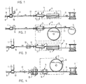
- Figures 1 and 2 of the drawings show an extruder 1, an associated grease filling device 2, a stretching device 3 and a receiving reel 4.
- the stretching device comprises a drawing means 5 and an idler wheel 6 the operating machineries of which are synchronized with each other in a known manner with a small speed difference.
- the drawing means 5 of the stretching device is formed by a reversible twisting caterpillar 7 the drive belts of which are adjustable between two extreme positions in which the belts are positioned at a larger or smaller angle with respect to each other, as shown with the double arrow in Figure 1.
- the drive belts move from one extreme position to the other over a middle position in which the belts are in parallel with each other and with the path of the sheathing.
- a fibre bundle 9 consisting of parallel fibres 8
- the sheathing is filled with grease.
- the drawing means draws the sheathing through it and at the same time twists the sheathing around its axis, whereby the grease filling forces the fibre bundle to follow the twisting movement of the sheathing.
- the sheathing then passes around the idler wheel 6 and further onto the receiving reel. On the periphery of the idler wheel, the fibre bundle is positioned against the inside of the sheathing so that the fibre bundle is locked axially immovably to the sheathing.
- the drawing means simultaneously brakes the movement of the sheathing to some extent, the sheathing is stretched between the drawing means and the idler wheel while the fibres slide axially in the grease within the area of the drawing means braking the sheathing.
- the stretch of the sheathing has returned after the idler wheel, the resulting cable element 11 to be reeled is in this way provided with an extra fibre length with respect to the sheathing.
- the twisting caterpillar twists the sheathing and the fibre bundle within it, it is ensured that the position of the fibres in the fibre bundle varies continuously when the fibre bundle reaches the periphery of the idler wheel. In this way it can be ensured that the same fibres in the fibre bundle will not always turn around the idler wheel with a shorter turning radius than the other fibres, so that the fibres are equally long after the stretching step.
- the drive belts of the caterpillar are adjusted from one extreme position to the other either continuously or periodically back and forth.
- the sheathing with the fibre bundle is first twisted in one direction until the fibre bundle has twisted to such an extent that the fibres are about to get interlocked longitudinally unslideably with respect to each other, whereafter the drive belts are displaced from the oblique position to the middle position.
- the drive belts are displaced to the other extreme position so that the caterpillar starts to twist the sheathing with its fibre bundle in the opposite direction.
- the drive belts are again displaced to the middle posi tion so that the fibre bundle starts to untwist, etc.
- the twist of the sheathing is straightened after the stretching device so that the fibres are completely or substantially untwisted in the sheathed cable element.
- the fibre bundle is twisted only to such an extent as is required to ensure that the twisted paths of the fibres in the fibre bundle will be equally long on the periphery of the idler wheel.
- the fibre bundle is twisted only to such an extent that the fibres are still able to slide in the longitudinal direction with respect to each other in the twisted fibre bundle.
- a twist 12 created in the sheathing by the twisting caterpillar 7 advances towards the extruder.
- Such a permanent twist is not disadvantageous because the sheathing is not in a strained state.
- a small twist gives firmness to the fibre bundle, wherefore a small permanent twist can be left in the sheathing in some cases.
- the apparatus shown in Figure 3 represents such a situation. It deviates from the apparatus shown in Figures 1 and 2 mainly in that a double belt device 13 preventing the twisting of the sheathing is mounted in front of the twisting caterpillar 5 on the side of the extruder. In this way it can be accurately determined how far towards the extruder the twist created by the twisting caterpillar extends.
- the apparatus shown in Figure 4 deviates from that shown in Figures 1 and 2 only in that the drawing means 5 of the stretching device is an ordinary caterpillar 14 which does not cause twisting.
- the sheathing is twisted by means of a reversibly rotating twisting wheel assembly 15 mounted in front of the caterpillar.
- the extra fibre length of the finished cable element is achieved by so-called thermal biasing in place of the stretching device. Accordingly, the sheathing is exposed to a controlled shrinking effect 18 by means of a locking drive wheel 19 and cooling basins 20, 21.
- a reversibly rotating twisting wheel assembly 15 acting as a drawing means is mounted in front of the locking drive wheel 19.
- the rotating twisting wheel assembly twists the sheathing and the fibre bundle before the fibre bundle is passed onto the periphery of the locking drive wheel.
- a reversible twisting caterpillar 7 acting as a drawing means is mounted in front of the locking drive wheel 19.
- a reversible twisting wheel pair 16 acting as a drawing means is mounted in front of the locking drive wheel 19.
- a twisting caterpillar or a similar device can be positioned after the device providing the extra length to untwist the sheathing.
Landscapes
- Physics & Mathematics (AREA)
- Engineering & Computer Science (AREA)
- Mechanical Engineering (AREA)
- Manufacturing & Machinery (AREA)
- General Physics & Mathematics (AREA)
- Optics & Photonics (AREA)
- Ropes Or Cables (AREA)
- Manufacture, Treatment Of Glass Fibers (AREA)
- Optical Fibers, Optical Fiber Cores, And Optical Fiber Bundles (AREA)
- Lubricants (AREA)
- Extrusion Moulding Of Plastics Or The Like (AREA)
- Detergent Compositions (AREA)
- Eye Examination Apparatus (AREA)
Applications Claiming Priority (2)
| Application Number | Priority Date | Filing Date | Title |
|---|---|---|---|
| FI895001A FI84110C (fi) | 1989-10-20 | 1989-10-20 | Foerfarande och utrustning foer tillverkning av ett flerfibrigt optiskt ledarelement. |
| FI895001 | 1989-10-20 |
Publications (3)
| Publication Number | Publication Date |
|---|---|
| EP0424151A2 true EP0424151A2 (fr) | 1991-04-24 |
| EP0424151A3 EP0424151A3 (en) | 1992-03-25 |
| EP0424151B1 EP0424151B1 (fr) | 1994-12-14 |
Family
ID=8529199
Family Applications (1)
| Application Number | Title | Priority Date | Filing Date |
|---|---|---|---|
| EP90311446A Expired - Lifetime EP0424151B1 (fr) | 1989-10-20 | 1990-10-18 | Méthode et dispositif pour la production d'un câble optique multifibre |
Country Status (6)
| Country | Link |
|---|---|
| US (1) | US5092117A (fr) |
| EP (1) | EP0424151B1 (fr) |
| CN (1) | CN1031477C (fr) |
| AT (1) | ATE115736T1 (fr) |
| DE (1) | DE69015109T2 (fr) |
| FI (1) | FI84110C (fr) |
Cited By (1)
| Publication number | Priority date | Publication date | Assignee | Title |
|---|---|---|---|---|
| WO2016162715A1 (fr) * | 2015-04-09 | 2016-10-13 | Draka Comteq Bv | Procédé de câblage sz de micromodules flexibles |
Families Citing this family (15)
| Publication number | Priority date | Publication date | Assignee | Title |
|---|---|---|---|---|
| JP2983628B2 (ja) * | 1989-08-17 | 1999-11-29 | コモンウェルス サイエンティフィク アンド インダストリアル リサーチ オーガナイゼイション | ステープルファイバの引き伸ばし |
| JP2683461B2 (ja) * | 1991-07-05 | 1997-11-26 | 住友電気工業株式会社 | 光ファイバケーブルの製造方法 |
| US5372757A (en) * | 1993-09-03 | 1994-12-13 | Tensor Machinery Ltd. | Apparatus and method for sheathing optical fibers |
| US5758483A (en) * | 1993-09-17 | 1998-06-02 | Commonwealth Scientific & Industrial Research Organisation | Twisting apparatus |
| US5647195A (en) * | 1995-06-29 | 1997-07-15 | Lucent Technologies Inc. | Method for twisting a pair of moving strands |
| WO1997007067A1 (fr) * | 1995-08-16 | 1997-02-27 | Plasma Optical Fibre B.V. | Fibre optique avec faible dispersion des modes de polarisation |
| AU1961997A (en) * | 1996-02-26 | 1997-09-10 | Corning Incorporated | Method and apparatus for providing controlled spin in optical fiber |
| US6405518B1 (en) * | 1996-11-12 | 2002-06-18 | Lucent Technologies Inc. | Optical fiber over the end payoff system |
| EP1141759B1 (fr) * | 1998-12-29 | 2003-07-09 | PIRELLI S.p.A. | Procede et appareil servant a fabriquer un cable a fibres optiques et cable ainsi fabrique |
| US7373055B1 (en) | 2007-01-09 | 2008-05-13 | Draka Comteq B.V. | System and method for providing a buffer tube including a jet |
| US20100166379A1 (en) * | 2008-12-31 | 2010-07-01 | E. I. Du Pont De Nemours And Company | Fiber guide for fiber optic cables |
| CN102855963B (zh) * | 2012-08-27 | 2015-09-02 | 大同电线电缆科技(吴江)有限公司 | 绞合线、含有该绞合线的电线及其制造装置和方法 |
| CN111736281B (zh) * | 2020-06-19 | 2022-05-06 | 武汉理工大学 | 一种解决余长问题的光纤光栅阵列测温光缆及工艺 |
| CA3231872A1 (fr) | 2021-09-14 | 2023-03-23 | Technical Development Corporation | Cabestan de serrage de tube tampon a quatre roues |
| CN114690356B (zh) * | 2022-05-31 | 2022-08-30 | 江苏亨通光电股份有限公司 | 多簇光纤带光缆及其光纤带成缆加工装置 |
Family Cites Families (12)
| Publication number | Priority date | Publication date | Assignee | Title |
|---|---|---|---|---|
| US3491525A (en) * | 1965-02-17 | 1970-01-27 | Sumitomo Electric Industries | Method for stranding in the manufacture of communication cables and stranding apparatus |
| DE2213693C2 (de) * | 1972-03-17 | 1973-12-06 | Siemens Ag, 1000 Berlin U. 8000 Muenchen | Verfahren zum Herstellen einer aus SZ verseiltex Verseileinheiten aufgebauten Verseilgruppe eines elektrischen Kabels |
| DE2735476C2 (de) * | 1977-08-04 | 1985-10-31 | Siemens AG, 1000 Berlin und 8000 München | Verfahren und Vorrichtung zur Herstellung von Kabeln und Leitungen mit SZ-verseilten Verseilelementen |
| DE2946248A1 (de) * | 1979-11-16 | 1981-05-27 | Kabel- und Metallwerke Gutehoffnungshütte AG, 3000 Hannover | Verfahren und vorrichtung zur kontinuierlichen verseilung von adern groesseren querschnitts fuer elektrische kabel |
| US4446686A (en) * | 1982-09-02 | 1984-05-08 | At&T Technologies, Inc. | Methods of and apparatus for controlling core-to-sheath length ratio in lightguide fiber cable and cable produced by the methods |
| WO1986006178A1 (fr) * | 1985-04-10 | 1986-10-23 | American Telephone & Telegraph Company | Cable a fibres optiques et procedes de fabrication |
| FI78576C (fi) * | 1986-04-01 | 1989-08-10 | Nokia Oy Ab | Foerfarande och anordning foer vaexelriktningstvinning. |
| GB8618662D0 (en) * | 1986-07-31 | 1986-09-10 | Telephone Cables Ltd | Cables |
| US4814116A (en) * | 1987-01-23 | 1989-03-21 | Siemens Aktiengesellschaft | Method for producing defined light waveguide lengths in an optical fiber cable |
| US4757675A (en) * | 1987-02-18 | 1988-07-19 | Ericsson Telecomcable | Process and apparatus for making fiber optic cable |
| DE3712338A1 (de) * | 1987-04-11 | 1988-10-20 | Philips Patentverwaltung | Verfahren und vorrichtung zur herstellung von lwl-buendeladern |
| DE3802867A1 (de) * | 1988-02-01 | 1989-08-03 | Philips Patentverwaltung | Verfahren zur herstellung eines optischen kabels |
-
1989
- 1989-10-20 FI FI895001A patent/FI84110C/fi not_active IP Right Cessation
-
1990
- 1990-10-16 US US07/598,275 patent/US5092117A/en not_active Expired - Fee Related
- 1990-10-18 AT AT90311446T patent/ATE115736T1/de not_active IP Right Cessation
- 1990-10-18 EP EP90311446A patent/EP0424151B1/fr not_active Expired - Lifetime
- 1990-10-18 DE DE69015109T patent/DE69015109T2/de not_active Expired - Fee Related
- 1990-10-20 CN CN90108526A patent/CN1031477C/zh not_active Expired - Fee Related
Cited By (3)
| Publication number | Priority date | Publication date | Assignee | Title |
|---|---|---|---|---|
| WO2016162715A1 (fr) * | 2015-04-09 | 2016-10-13 | Draka Comteq Bv | Procédé de câblage sz de micromodules flexibles |
| AU2015390722B2 (en) * | 2015-04-09 | 2021-03-04 | Draka Comteq Bv | A method of SZ stranding flexible micromodules |
| US10948679B2 (en) | 2015-04-09 | 2021-03-16 | Draka Comteq Bv | Method of SZ stranding flexible micromodules |
Also Published As
| Publication number | Publication date |
|---|---|
| CN1031477C (zh) | 1996-04-03 |
| US5092117A (en) | 1992-03-03 |
| EP0424151B1 (fr) | 1994-12-14 |
| CN1050932A (zh) | 1991-04-24 |
| EP0424151A3 (en) | 1992-03-25 |
| DE69015109T2 (de) | 1995-04-27 |
| FI895001A0 (fi) | 1989-10-20 |
| DE69015109D1 (de) | 1995-01-26 |
| FI84110B (fi) | 1991-06-28 |
| FI84110C (fi) | 1991-10-10 |
| ATE115736T1 (de) | 1994-12-15 |
Similar Documents
| Publication | Publication Date | Title |
|---|---|---|
| EP0424151A2 (fr) | Méthode et dispositif pour la production d'un câble optique multifibre | |
| DE69318291T2 (de) | Verfahren und einrichtung zur herstellung eines verbindungskabels | |
| EP0424150A2 (fr) | Méthode et dispositif pour la production d'un câble optique multifibre | |
| DE2922986C2 (fr) | ||
| DE69916079T2 (de) | Verfahren und vorrichtung zum drehen einer beschichteten optischen faser während des ziehens aus einer vorform | |
| EP0521503B1 (fr) | Méthode et appareil de fabrication d'un câble de fibres optiques | |
| CH140512A (de) | Verfahren zur Herstellung von elektrischen Mehrleiterkabeln mit Adern von unrundem Querschnitt. | |
| DE69311103T2 (de) | Verfahren und Vorrichtung zum reversierenden Verseilen | |
| EP0492293A2 (fr) | Procédé de fabrication d'un câble optique | |
| US6389787B1 (en) | Optical fiber ribbon twisting device and system for use in the manufacture of fiber optic cable components | |
| CA1308971C (fr) | Dispositif d'insertion de fibres optiques dans les rainures helicoidales d'un anneau de ligne de cablage | |
| DE2211111C3 (de) | Verfahren und Vorrichtung zum maschinellen Verseilen gestreckter elektrischer Einzelleiter mit unrunden Querschnitten zu einem Kabel | |
| DE69109178T2 (de) | Verkabelungsmaschine. | |
| EP0327164B1 (fr) | Procédé de fabrication d'un câble optique | |
| DE69909515T2 (de) | Verfahren und gerät zur herstellung eines optischen kabels und derart hergestelltes kabel | |
| US4089154A (en) | Taping device, particularly for optical fibres | |
| AU635085B2 (en) | A method of and an apparatus for producing an optical multi-fibre cable element | |
| DE2900729C2 (de) | Vorrichtung zum SZ-Verseilen von Verseilelementen elektrischer Kabel und Leitungen sowie Verfahren zum Betrieb dieser Vorrichtung | |
| CA1277524C (fr) | Supports canneles pour fibres optiques | |
| FR2532464A1 (fr) | Procede et dispositif de cablage a sens alterne du pas de torsion dit sz et le produit obtenu selon le procede | |
| DE3414396A1 (de) | Verseilverfahren und verseileinrichtung zur durchfuehrung des verfahrens | |
| DE4322770A1 (de) | Verfahren zur Herstellung eines optischen Kabels |
Legal Events
| Date | Code | Title | Description |
|---|---|---|---|
| PUAI | Public reference made under article 153(3) epc to a published international application that has entered the european phase |
Free format text: ORIGINAL CODE: 0009012 |
|
| AK | Designated contracting states |
Kind code of ref document: A2 Designated state(s): AT BE CH DE DK ES FR GB GR IT LI LU NL SE |
|
| PUAL | Search report despatched |
Free format text: ORIGINAL CODE: 0009013 |
|
| AK | Designated contracting states |
Kind code of ref document: A3 Designated state(s): AT BE CH DE DK ES FR GB GR IT LI LU NL SE |
|
| 17P | Request for examination filed |
Effective date: 19920602 |
|
| 17Q | First examination report despatched |
Effective date: 19931207 |
|
| GRAA | (expected) grant |
Free format text: ORIGINAL CODE: 0009210 |
|
| AK | Designated contracting states |
Kind code of ref document: B1 Designated state(s): AT BE CH DE DK ES FR GB GR IT LI LU NL SE |
|
| PG25 | Lapsed in a contracting state [announced via postgrant information from national office to epo] |
Ref country code: IT Free format text: LAPSE BECAUSE OF FAILURE TO SUBMIT A TRANSLATION OF THE DESCRIPTION OR TO PAY THE FEE WITHIN THE PRE;WARNING: LAPSES OF ITALIAN PATENTS WITH EFFECTIVE DATE BEFORE 2007 MAY HAVE OCCURRED AT ANY TIME BEFORE 2007. THE CORRECT EFFECTIVE DATE MAY BE DIFFERENT FROM THE ONE RECORDED.SCRIBED TIME-LIMIT Effective date: 19941214 Ref country code: DK Effective date: 19941214 Ref country code: ES Free format text: THE PATENT HAS BEEN ANNULLED BY A DECISION OF A NATIONAL AUTHORITY Effective date: 19941214 Ref country code: GR Free format text: LAPSE BECAUSE OF FAILURE TO SUBMIT A TRANSLATION OF THE DESCRIPTION OR TO PAY THE FEE WITHIN THE PRESCRIBED TIME-LIMIT Effective date: 19941214 Ref country code: NL Effective date: 19941214 Ref country code: BE Effective date: 19941214 Ref country code: FR Effective date: 19941214 |
|
| REF | Corresponds to: |
Ref document number: 115736 Country of ref document: AT Date of ref document: 19941215 Kind code of ref document: T |
|
| REF | Corresponds to: |
Ref document number: 69015109 Country of ref document: DE Date of ref document: 19950126 |
|
| PG25 | Lapsed in a contracting state [announced via postgrant information from national office to epo] |
Ref country code: SE Effective date: 19950314 |
|
| EN | Fr: translation not filed | ||
| NLV1 | Nl: lapsed or annulled due to failure to fulfill the requirements of art. 29p and 29m of the patents act | ||
| PG25 | Lapsed in a contracting state [announced via postgrant information from national office to epo] |
Ref country code: GB Effective date: 19951018 |
|
| PLBE | No opposition filed within time limit |
Free format text: ORIGINAL CODE: 0009261 |
|
| STAA | Information on the status of an ep patent application or granted ep patent |
Free format text: STATUS: NO OPPOSITION FILED WITHIN TIME LIMIT |
|
| PG25 | Lapsed in a contracting state [announced via postgrant information from national office to epo] |
Ref country code: LU Free format text: LAPSE BECAUSE OF NON-PAYMENT OF DUE FEES Effective date: 19951031 |
|
| 26N | No opposition filed | ||
| GBPC | Gb: european patent ceased through non-payment of renewal fee |
Effective date: 19951018 |
|
| PGFP | Annual fee paid to national office [announced via postgrant information from national office to epo] |
Ref country code: AT Payment date: 19981002 Year of fee payment: 9 Ref country code: DE Payment date: 19981002 Year of fee payment: 9 |
|
| PGFP | Annual fee paid to national office [announced via postgrant information from national office to epo] |
Ref country code: CH Payment date: 19981019 Year of fee payment: 9 |
|
| PG25 | Lapsed in a contracting state [announced via postgrant information from national office to epo] |
Ref country code: AT Free format text: LAPSE BECAUSE OF NON-PAYMENT OF DUE FEES Effective date: 19991018 |
|
| PG25 | Lapsed in a contracting state [announced via postgrant information from national office to epo] |
Ref country code: LI Free format text: LAPSE BECAUSE OF NON-PAYMENT OF DUE FEES Effective date: 19991031 Ref country code: CH Free format text: LAPSE BECAUSE OF NON-PAYMENT OF DUE FEES Effective date: 19991031 |
|
| REG | Reference to a national code |
Ref country code: CH Ref legal event code: PL |
|
| PG25 | Lapsed in a contracting state [announced via postgrant information from national office to epo] |
Ref country code: DE Free format text: LAPSE BECAUSE OF NON-PAYMENT OF DUE FEES Effective date: 20000801 |